
International Research Journal of Engineering and Technology (IRJET) e-ISSN:2395-0056
Volume: 11 Issue: 04 | Apr 2024 www.irjet.net p-ISSN:2395-0072
International Research Journal of Engineering and Technology (IRJET) e-ISSN:2395-0056
Volume: 11 Issue: 04 | Apr 2024 www.irjet.net p-ISSN:2395-0072
CH.B. Srikanth M.tech (Phd),Y. Jagadeesh, B.Balaji Arun, P.Vijay, M. Jyoshna
CH.B.Srikanth M.tech (Phd), professor, Dept. of EEE, Visakha institute of engineering and technology, India.
Y. Jagadeesh, student, Dept. of EEE, Visakha institute of engineering and technology, India
B. Balaji Arun, student, Dept. of EEE, Visakha institute of engineering and technology, India
P. Vijay, student, Dept. of EEE, Visakha institute of engineering and technology, India.
M. Jyoshna, student, Dept. of EEE, Visakha institute of engineering and technology, India. ***
Abstract - This project presents the design and implementation of a speed control system for a Brushless DC Motor (BLDC) using PID Controller . The objective is to regulate the speed of the BLDC Motor efficiently and accurately, whereas the PID serves as the executing unit, In which the VSC converter employed to provide the appropriate voltage input to the BLDC Motor. For the steady state behavior of the motor we use PID Controller, which in general is tuned to achieve desired speed responses. The total integration of all these components results to achieve the precise speed control for the BLDC Motor. The experimental results validate the proposed approaches performance and it is potential for various industrial and automation applications. The suitability of proposed system at practical operating conditions is demonstrated through simulation results using MATLAB/ Simulink followed by an experimental validation.
Key Words: Burshless DC motor (BLDC), PID Controller, VSC , Modelling
1.INTRODUCTION
InthismodernIndustrialeratheelectricalmotorsplaysa majorkeyroleinindustrialdevelopment,Asweknowthat motors are classified according power fed to them as Ac motors, Dc motors. One of the most important motors in commercial segment is BLDC motor which is usually known as electronically commutated motor ,The BLDC motors works on both low voltage DC, high voltage AC. BLDC motors are increasing its popularity in automotive sector for light load vehicles like two wheeler, cars which are most efficient and reliable as there is no mechanical commutator.
The speed control of a BLDC motor in commercial segment is a important task there are many methods are usually used for speed controlling of BLDC motor like PI controller. But the experiment gives best results with PID controllerusingvoltagesourceconverter.
Brushless DC motors have gained widespread acceptance in various industrial and consumer applications due to
their high efficiency, reliability, and controllability. Unlike traditional brushed motors, BLDC motors rely on electronic commutation, making them suitable for applications requiring precise speed control. Among the various methods employed for regulating BLDC motor speed, A BLDC motor is a special type of DC motor that doesnotapplyabrushfortransport,insteadanelectronic process system is used for this purpose. The BLDC motor isusuallyasynchronousmotorcomposedofatrapezoidal backEMFwaveformandapermanentmagnet.Thecurrent trend shows that high-performance BLDC motor technologies are widely used for global industrial applicationsandvariablespeeddrives inelectricvehicles. Infact,thesetypesofmotorsdependonitscontrolcircuit. These types of motors rely on its control circuit and still developingahighperformancecircuitisachallengingtask for researchers. The structure of the BLDC motor tuning control project selection, modelling simulation and so on. The design structure of a BLDC motor is a complex task and depends on many issues such as project selection, modeling, simulation, etc. In terms of the rapidity framework of the BLDC motor, a host of modern control solutionshavebeenproposed.
ThemethodsusedforthespeedcontroloftheBLDCMotor use the dual closed loop speed control in which the one loop is used to limit the current or govern the current controlorforthecontrolofthegatepulses.Theotherloop isforspeedcontrolwhichisusedtogetthedesiredspeed as per the requirement. The required speed can be either set as an integer value or can be given as step input. The reference speed is given as a constant value which canbe changed based on the requirement and accordingly the desired speed can be obtained. The methods used in this paperarenamelyspeedcontrolusingPIDcontroller,using CurrentController and a closed loop speed control. These methods are compared based on the values of current total harmonic distortion (THD), output current (RMS value) and on the values of rise time and settling time of thespeedresponseofvariousmethods.
International Research Journal of Engineering and Technology (IRJET) e-ISSN:2395-0056
Volume: 11 Issue: 04 | Apr 2024 www.irjet.net p-ISSN:2395-0072
TheanalysisofBLDCmotorisbasedontheassumptionfor simplification and accuracy. The BLDC motor is type of unsaturated.Thestatorresistancesforallthewindingare equal and the self and mutual inductance are constant. Semiconductor devices of inverter are ideal and iron losses are negligible. Meanwhile, the back-EMF waveforms of all phases are equal. Based on the equivalent circuit of BLDC motor and VSI system , the dynamic equations of BLDC motor using the assumption can be derivedas
Va= RIa+(L-M) dia/dt+ea (1)
Vb=RIb+(L-M) dib/dt+eb (2)
Vc=RIc+(L-M) dic/dt+ec (3)
Basically it is an electronic motor and requires a threephase inverter in the front end In self-control mode the inverter acts like an electronic commutator that receives the switching logical pulse from the absolute position sensors. The drive is also known as an electronic commutated motor Basically the inverter can operate in thefollowingmode.
Inverteroperationinthismodewiththehelpofthewave sixswitchesoftheinverter(T1−T6)operateinsuchway soastoplacetheinputdccurrentId symmetricalfor120 degrees angle at the center of each phase voltage wave. The angle shown is the advance angle of current wave with respect to voltage wave in the case zero. It can be seen that any instant ,two switches are on, one in the upper group and another is lower group. For example instantt1 T1andT6 areonwhenthesupplyvoltageVdc andcurrentId areplacedacrossthelineab(phaseAand phase B in series) so that Id is positive in phase a . But negative in phase b then after 120 degree interval (the middleofphaseA).T6isturnedoffandT2isturnedonbut T1continuesconduction of the full 180dgreeangle. This switching commutates –Id from phase b to phase c while phase a carry +Id the conduction pattern changes every 120degreeangleindication switchingmodes in full cycle. The absolute position sensor dictates the switching or communication of devices at the precise instant of wave. The inverter basically operating as a rotor position sensitive electronic commutator.
PID controller is used for controlling the speed of BLDC motor. The feedback speed from the motor is compared with the reference speed. The error speed is then passed through the PID controller which then is given directly to the controlled Voltage Source. The voltage source is a DC Voltage Source which gives supply to the MOSFET bridge. The bridge converts the DC supply into the 3-phase AC supplywhichisthengiventothemotor.
The motor gives various outputs including stator currents, Hall Effect signals, back EMF voltages, electromagnetic torque and speed of the rotor (in rps). The output from the Hall Sensors is then used to determine the position of the rotor of the motor. These signals form a closed loop in which these signals are convertedintotheEMFsignalsandagainconvertedtothe gatesignalsusing different topologiesandis converted to the gate signals based on the number of switches connected in the MOSFET bridge. These signals serve as the gate signals for controlling the voltage which in turn controltheinputvoltagetothemotorwhichinturnhelps in controlling speed of the motor. The foundational frequency transferring performance G(s) of the PID controllercanberepresentedby(1)and(2),
G(s)=Kp+Ki/s+Kds (1)
G(s)=(Kds2+Kps+Ki)/s (2)
The time derivative output U(t) of the controller for control of the plant is equal to Kp times the magnitude of error pulse Kdtimes the derivative of time function error signal e(t)and Kitimestheintegral canberepresented by (3).
U(t)=Kpe(t)+Ki∫e(t)dt+Kdde(t)/dt(3)
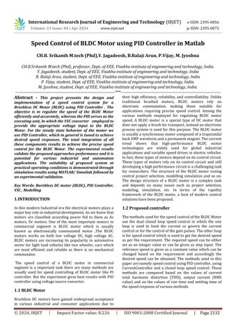
2-motor’s speed response with PID controller in SIMULINK
International Research Journal of Engineering and Technology (IRJET) e-ISSN:2395-0056
Volume: 11 Issue: 04 | Apr 2024 www.irjet.net p-ISSN:2395-0072
The speed control of BLDC motor done through the simulink Matlab, the BLDC motor has been modified accordingtorequirements
Table 1. Machine parameters
Parameters
StatorPhasorresistance(Rs) 0.7ohm
Armatureinductance
2.72e-3H
Fluxlinkageestablishedbymagnets 0.105Wb
Voltageconstant 87.9646 (V/krpm)
Torqueconstant 0.84(N/A)
Inertia 08e-3J
Viscousdamping 1e-3
Polepairs 4
Staticfriction 0
Numberofphases 3
BackEMF Trapezoidal
MechanicalInput Torque
BackEMFflatarea(degrees) 120⁰
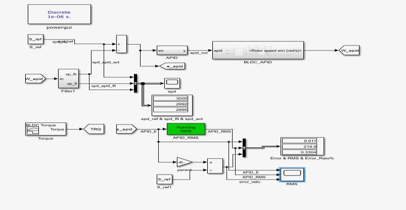
3.1. Speed control using PIDcontroller
The speed control is achieved by proportional and integral derivative controller. The output waveforms for speed characteristics shown These characteristics of the BLDCmotorcanhelpindeterminingwhichmethodisbest among. In order to reduce the instability the PID control method is proposed and enhanced speed performance compared to the conventional methods. The 5% error is allowed for the error in the value of the actual speed, as the error may occur due to the switching states, friction force in the machine or due to the operation under variablefrequency.
A BLDC motor controller has been successfully designed based on PID controller scheme and compared its performance with other controller. From the results, it is observed that the PID controller provides the best performance compared to the other controller logic. The designhasbeenvalidatedbyMATLABsimulation.
[1] P. Pillay and R. Krishnan, “Modelling, simulation and analysis of permanent magnet motor drives-Part I: The permanent magnet synchronous motor drive,” thisissue,pp.265-273.
[2] J.Moreno, M.E.Ortuzar, and J.W.Dixon, “Energymanagement system for a hybrid electric vehicle, using ultracapacitors and neural networks,” in IEEE Transactions on Industrial Electronics, vol. 53, no. 2, pp.614-623,April2006,doi:10.1109/TIE.2006.870880.
[3] S.X.Chen,M.A.Jabbar,Q.D.Zhang,andZ.J.Liu,“New challenge: electromagnetic designof BLDCmotors for high speed fluid film bearing spindles used in hard disk drives,” in IEEE Transactions on Magnetics, vol. 32,no.5,pp.38543856,Sept.1996,doi:10.1109/20.539195.