
International Research Journal of Engineering and Technology (IRJET) e-ISSN: 2395-0056
Volume: 11 Issue: 04 | Apr 2024 www.irjet.net p-ISSN: 2395-0072
International Research Journal of Engineering and Technology (IRJET) e-ISSN: 2395-0056
Volume: 11 Issue: 04 | Apr 2024 www.irjet.net p-ISSN: 2395-0072
Asst.Professor R. Mahalakshmi1, H. Likhitha2, K. Gulshan kumar3, M. Anil kumar4
1Asst.Professor, Dept. of EEE, Visakha Institute of Engineering & Technology, A.P, India
2Student, Dept. of EEE, Visakha Institute of Engineering & Technology, A.P, India
3Student, Dept. of EEE, Visakha Institute of Engineering & Technology, A.P, India
4Student, Dept. of EEE, Visakha Institute of Engineering & Technology, A.P, India
Abstract – Closed-loop chopper-controlled DC motor drives are sufficient in range of industrial and Consumer applications due to their precise speed and required control capabilities. This technology offers the advantages of DC motors with the precision of closed-loop control systems, resultinginefficientandreliablemotoroperation.ToEnhance the performance of DC motors closed loop control systems have been developed and one of the key technologies is Chopper control. The chopper circuit is responsible for regulatingthevoltagesuppliedtotheDCmotor,itcanoperate in four quadrants, meaning that it can provide positive or negative voltage and current to the motor, allowing it to run in forward or reverse direction and to brake in regenerative mode Speed controller (PI) and current controller plays a crucial role in maintaining desired motor behavior by adjustingthechopperpulsewidth modulation(PWM)signals
Key Words: Choppers, Closed loop, Speed controller, DC motor drives, Four quadrant operation, DC power, wave forms
Closed-loop chopper-controlled DC motors represent a sophisticatedandfasterapproachtomotorcontrol,enabling preciseandefficientresultsofmotorspeedandtorque Here separatelyexcited dc motor drive is used because of its flexiblecontrolcharacteristicsinwhichchopperisusedto controlthemotorspeedduetoitslessloss,highefficiency, lightweight,andquickresponse. Theclosedloopcontrolof the chopper drive consists of two loops: an inner current loopandouterspeedloop.Theinnercurrentloopregulates thearmaturecurrentofthemotorbycomparingtheactual currentwiththereferencegivencurrent,whichisderived fromtheouterspeedloop.Thespeedloopcontrolsthespeed ofthemotor bycomparing with theactual speedwiththe referencespeed,whichisusuallysetbytheuserorahigherlevelcontroller.Thespeedloopcontrollercanalsoadjustthe reference current according to the load torque and the operatingmodesofthedrive.
1.1 Choppers:
AChopperis a high-speed semiconductor switch(S) that operatesinan“on”or“off”state.Choppercircuitisatypeof DCtoDCconverters TheychangethefixedinputDCvoltage
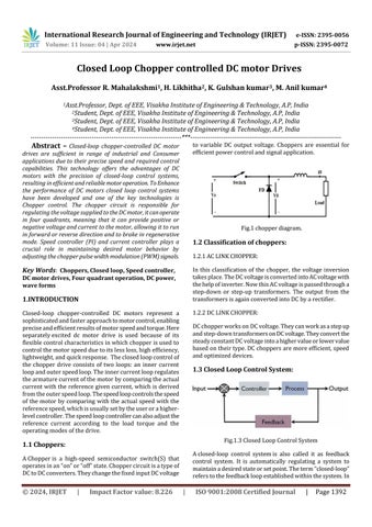
to variable DC output voltage. Choppers are essential for efficientpowercontrolandsignalapplication
Fig.1chopperdiagram.
1.2 Classification of choppers:
1.2.1ACLINKCHOPPER:
In this classification of the chopper, the voltage inversion takesplace.TheDCvoltageisconvertedintoACvoltagewith thehelpofinverter.NowthisACvoltageispassedthrougha step-down or step-up transformers. The output from the transformersisagainconvertedintoDCbyarectifier
1.2.2DCLINKCHOPPER:
DCchopperworksonDCvoltage Theycanworkasastepup andstep-downtransformersonDCvoltage.Theyconvertthe steadyconstantDCvoltageintoahighervalueorlowervalue basedontheirtype.DCchoppersaremoreefficient,speed andoptimizeddevices.
1.3 Closed Loop Control System:
Fig.1.3ClosedLoopControlSystem
Aclosed-loop control systemis also called it as feedback control system. It is automatically regulating a system to maintainadesiredstateorsetpoint.Theterm“closed-loop” referstothefeedbackloopestablishedwithinthesystem.In
International Research Journal of Engineering and Technology (IRJET) e-ISSN: 2395-0056
Volume: 11 Issue: 04 | Apr 2024 www.irjet.net p-ISSN: 2395-0072
thisloop,theoutputiscontinuouslymonitoredandusedto correctthesystem’sperformance.Theobjectiveofaclosedloop control system is to enhance stability, accuracy, and overallperformance.
ErrorDetectorComparesthedesiredoutput(setpoint)with theactualoutputandgeneratesanerrorsignal.Itcomputes theerrorsignalbycomparingtheinputandfeedbacksignals ControllerProcessestheerrorsignalandproducesanactual signal tocontrol thesystem.FeedbackElements isusedto Provide information about the system’s output (feedback signal).PowerPlantRepresentsthephysicalprocessbeing controlled. The actual signal controls the power plant (process)toachievethedesiredoutput.
A Four quadrants chopper is also called it as a class- E Chopper.Aclass-Echopperisatypeofdcchopperthathas the capability to operate in all four quadrants of output voltageandcurrent.Theoutputvoltageandcurrentcanbe positiveornegative Aclass-Echoppercircuitisformedby theparallelcombinationoftwoclass-Cchoppercircuits.This circuitconsistsoffourswitches(CH1-CH-4)andfourdiodes (D1,D2,D3,andD4).
The operation of a class-E chopper in four quadrants is obtained by turning ON different switches and diodes combinations.FreeWheelingdiodeisconnectedinorderto improvethewaveformofloadcurrentandpowerfactorof thecircuit.ItisalsocalledasBy-passdiode.
Toobtainfirstquadrantoperation,thecircuitoperatesasa step-down chopper. The output voltage Voand current Ioshouldbepositive.TheswitchesCH1andCH4areturned ON,theloadgetsconnectedacrossthesource.
Thus,loadvoltagebecomesequaltothesourcevoltage,and theloadcurrentstartsflowinginthecircuitfromsource
Toobtainthesecondquadrantoperation,theoutputvoltage Voshould be positive, and output current Ioshould be negative.Theloadwillactasthedcsource(generator).Here switchCH2isoperatedwhilekeepingotherswitchesOFF.
To obtain third quadrantoperation,outputvoltage Voand current Ioshould be negative. Load voltage and current shouldbenegative.Inordertooperateaclass-Echopperin thethirdquadrant,thepolarityofloademfmustbereversed.
To obtain the fourth quadrant operation, output voltage Voshould be negative, and output current Ioshould be positive. To obtain the fourth quadrant operation CH4is operated,thusloadEMFdrivescurrentthroughS4,D2,and load.
1.5Blockdiagramofclosedloopchopper-controlledDC motordrives.
From the above diagram, Speed Controller Compares the actual speed with the reference speed (*) and adjusts the choppercontroltomaintainthedesiredspeedlevel.Current ControllerMaintainsthemotorcurrentwithinthesafelimits. It ensures that the motor current stays within predefined limits to protect the motor and the chopper. Firing circuit providewaveformsanddutyratiotocontrol thechopper. ChopperModulatestheDCvoltagetothemotor.Thiscircuit isresponsibleforcontrollingtheamountofpowersupplied tothemotorbychoppingtheDCvoltage.Ittypicallyconsists of switches (like MOSFETs or IGBTs) and diodes. Filter is
International Research Journal of Engineering and Technology (IRJET) e-ISSN: 2395-0056
Volume: 11 Issue: 04 | Apr 2024 www.irjet.net p-ISSN: 2395-0072
usedtoeliminatetheunwanteddisturbancesorerrors.Here Separatelyexciteddcmotorisused.Speedsensorchecksthe speedofthemotorandcurrentsensormeasurestheactual currentofthemotor
Fromthediagram,itconsistsoftwoloops:innercurrentloop andanouterspeedloop.Outerspeedloopfeedbacklinewill generate the error signals at set point. Speed controller stabilizestheerrorsignalsandconvertittocurrentsignalthe fed to current limiter. Current limiter generates reference currentvalueandthengiventhissignaltoinnercurrentloop. Inner current loop ensures the accurate current level and suddenchangeintorquedemandandthenfedtochopper. HereChopperactsasaconverterandregulatesitsvoltageto motorterminals.SeparatelyexcitedDCmotoradjustitsbase speedandrunatthegivenspeedatsetpoint.Speedsensor checks the speed of the motor as well as current sensor checksthemotorcurrent.Atlast,threeparametershavebeen determinedbyusingthedisplays.
drives
IntheMATLABsimulation,thistypicallyincludesaDCmotor, chopper,voltageandcurrentmeasurementsandthecontrol system.HereMOSFET(Metaloxidesemiconductorfieldeffect transistor) is used as a chopper switch for the better performance, Faster Switching and low losses. MOSFET consists of four terminals that has drain, source, base and gate. Separately excited DCmotor is usedandadditionally 240 V DCsupply is given to the field. Model thearmature, field, back EMF and Load torque. Armature terminals are connected to voltage and current measurements inputs to measure the instantaneous voltage and current. These outputsareconnectedtoscopestoseethewaveforms.Load torqueshouldtoconnecttoconstantblockinordertogive theloadtorquevalues.PowerGuiShouldarrangeatthetop placeforoptimalperformance.
In MATLAB simulation. Four Quadrant chopper-controlled operationisused.Thechoppercircuitisusedtocontrolthe speedandregulatethevoltageoftheDCmotorbyvaryingthe average voltage applied to it Here Freewheeling diode is connectedinparallelanditisusedforsmoothperformance andimprovethewaveformsofloadcurrent.Alsoneedtoset up the appropriate interfaces between these components. The Drive features closed loop control with four quadrant operation.Inafour-quadrantdrive,allfourquadrantsofthe speed-torqueplaneareoperated.indicatingforward/reverse andmotoring/brakingcapabilities.
Oncethemodelissetupwithalltheproperconnections,set thetimetoanalyzetheconnections.Onceitisdone,runthe simulationwithvariousinputconditionsandparametersto observethesystem.Thisallowstoanalyzetheperformance oftheclosed-loopcontrolsystemunderdifferentoperating conditions.It'simportanttovalidatethesimulationresults againstexperimentaldataorknownmodelstoensurethat thesimulationisdonewithouterrors.Finally,youmayneed tooptimizethecontrolparameterssuchasspeedandcurrent controllersandchoppersettingstoimprovetheperformance ofthesystem,such asreducingsettlingtimeorovershoot. The system response to these inputs is observed through waveforms.
Simulation output results ofclosed loop model of chopper controlledwithDCmotorisdisplayedbelow.Thesimulated output parameters are speed, load torque and armature current.
(a)Speed
(b)ArmatureCurrent
International Research Journal of Engineering and Technology (IRJET) e-ISSN: 2395-0056
Volume: 11 Issue: 04 | Apr 2024 www.irjet.net p-ISSN: 2395-0072
Speedwaveformdisplaystheactualspeedofthemotor.It shouldrisetomatchthereferencespeedandshouldmaintain the desired level. Armature current waveform shows the currentflowingthroughthemotor’sarmature.InClosedloop system,thecurrentshouldimmediatelyreachthereference valuesetbythecontroller.Thiswillreflectthemotor’storque and speed characteristics. Torque waveform indicates the torqueproducedbythemotor.It’sreflectedthemotorload characteristics.Choppercontroladjustthevoltagetoregulate the torque output. These three waveforms show how the motor speed, torque and armature current respond the changesintheoutputsignalsandhoweffectivelytheclosed loopcontrolsystemmaintainstheaccurateperformance.
Inconclusion,ClosedloopchoppercontrolledofDCMotoris successfully done. The speed of the DC motor has been successfully controlled by using chopper as converter Current controllerandspeedcontrollerplaysakeyrolein this Closed loop operation. The Modeling of separately excited DC motor is done. The design of Four quadrant chopper circuit is done by choosing MOSFET as semiconductorswitch.TheMATLAB/SIMULINKmodeldisplayed good results under all conditions during simulation. The future of closed-loop chopper-controlled DC motor drives offersignificantpromise,withongoingdevelopmentsaimed atfurtherimprovingtheirefficiency,reliability
1) C.A.Monjeetal.(2010):AFractional-orderSystemsand Controls:FundamentalsandApplications,Springer.
2) J.Sabatieretal.(2015):FractionalOrderDifferentiation and Robust Control Design: CRONE, H-infinity and MotionControl,Springer.
3) M.Beschi,F.Padula&A.Visioli(2015):TheGeneralized Iso damping Approach for Robust Fractional PID ControllersDesign,InternationalJournalofControl,DOI: 10.1080/00207179.2015.1099076
4) SE.Hamamci(2007):AnAlgorithmforStabilizationof FractionalOrderTimeDelaySystemsUsingFractional-
OrderPIDControllers,IEEETransactionsonAutomatic Control,Vol.52,No.10,pp.1964-1969
5) LivintiPetru,GhandourMazen,“PWMControlofaDC Motor Used to Drive a Conveyor Belt”, 25th DAAAM InternationalSymposiumonIntelligentManufacturing andAutomation,DAAAM2014.