
International Research Journal of Engineering and Technology (IRJET) e-ISSN: 2395-0056
Volume: 11 Issue: 04 | Apr 2024 www.irjet.net p-ISSN: 2395-0072
International Research Journal of Engineering and Technology (IRJET) e-ISSN: 2395-0056
Volume: 11 Issue: 04 | Apr 2024 www.irjet.net p-ISSN: 2395-0072
Asst.Professor S Jyothirani 1 , P Raghavaprasad2 , P chanikya3 , P Pradeep kumar4
M Surya Bhargav5 , S Mounika6
1Head of Department, Dept. Visakha Institute of Engineering & Technology, A.P, India
2Student, Dept. of EEE, Visakha Institute of Engineering & Technology, A.P, India
3Student, Dept. of EEE, Visakha Institute of Engineering & Technology, A.P, India
4Student, Dept. of EEE, Visakha Institute of Engineering & Technology, A.P, India
5Student, Dept. of EEE, Visakha Institute of Engineering & Technology, A.P, India
6Student, Dept. of EEE, Visakha Institute of Engineering & Technology, A.P, India
Abstract - This paper presented by voltage sourcecontrolled by the inverter by using the induction motor drivescontrolling and using the generation of firing angles to IGBT of the inverter using modulation produces balancing pulses with Output Voltages, Current waveforms, rotor and stator are the magnitude angles speed and Torque multi wave angles are calculated and harmonic distortion lines. Voltage source inverter in degree in module operation 180 degrees to 360 degrees operationpulseswidthmodulationvoltagegenerating output mechanically operation of microcontroller proper switching of drives circuit consists load impedance.
Key Words: PWM Inverter, VectorModulation,IGBT,VSI, Inductionmotordrives,MATLAB,Switching
1.INTRODUCTION
Project involve the using varying the voltage source of Inverter fed induction motor using drives are generating voltage supplies from the pulse generation modulated to integratedfromtheIGBTswitchesoperationofGTO(Gate turnandoff)thyristorsinsulatinggateoperationssteppedas an integrated operation switches increasing losses operation. Voltage supplies from Asynchronous Machine varying speed operation of the rotor speed and Electromagnetic torque or stator current and finding operationofapulsemodulationtechniques.Operationofa conversation of AC link converted from the DC source of operation,NotethevaluesofDChigh-linkoperationofbased requiredfromthevaryingspecificvaluesarerequiredand designconsiderationoperationtechniquesofMATLAB(dc) chargesofacapacitorvoltagebalancingrisingvaluesmotor performance.
Conversion of a DC-AC inverter operation voltage dc energy to battery are conversion of AC pulse operated voltage have inverter performance easily AC switches to threephaseconversion.
Voltage source inverter controlled by induction motor drivesarecontrolledbythevaryingfrequencyobtainedfrom theACtoDCconversiontechniquesoperationofswitching devise are GTO Gate turn and off transistor switching of directcurrentfromtheasynchronousmotorconvertfrom themechanicallytooperatedharmonicwavesofperfectout the varying stepped wave to PWM line voltage waveform. Sinusoidal modulation operation of single line voltage 230v,50hzlargenumberofripplesfreedcoutputoperation 180degreesconditionmagnitudewave,microwavesvoltage andcurrentwaves.
Inverter which takes DC supply and constant the magnitudeofloadcurrentdependsonloadImpedance.They are communicating device MOSFET, GTO, IGBT operated pulseoperationsequenceofT/6,eachoftimedurationT/2 theoutvoltagefromacandinputdcinputcontrollingfroma stableinputdevicefromchoppersareusingandcontrolling the motor operation of stable condition filtration input constantvaryingvoltage.
when the not using for (choppers) motor performs the jerky motion, input voltage or current not at stabling conditionofwaveform.[Themaindrawbackisharmonicis increasing the harmonic losses in motor jerky of rotor speed.] The energy stored capacitor flows the resistance reduce the normal switching (off) condition operation of dynamicbraking.
Whenthesupplyfromthedcvoltagecoppersisconnected as integrated from the IGBT switches of pulse generator connected with chopper linked a conversion of ac source controlled by rectifier Increasing voltage from the jerky motion of rotor speed either low and speed reduces the losses Pulse generating for electrical operation thyristor switchingandcontrollingtheusingfrequencyoperated of fedinductionmachine.Voltagesourceisusedtocontrolthe
International Research Journal of Engineering and Technology (IRJET) e-ISSN: 2395-0056
Volume: 11 Issue: 04 | Apr 2024 www.irjet.net p-ISSN: 2395-0072
speedandcontrolthemotorusedthevoltagesourceinverter andeitherhighandlowfrequencywaveformscontrolspeed ofinverterusedbytheconstantspeedvarioussupplytothe loadconnectionandfrequencyapplytheloadconditionto thesourcesupplytostudythemaximumsupplyingcontrol MATLAB/controlofstudy.
The potential difference from two points and active elements from battery, cells, generator etc. The constant speed of a storying capacity of varying source switching operation of IGBT switches particular varying sources voltageofinverterstoryingcellsofactiveelement.
TheswitchingfrequencyofVSIresultingrippleorcurrent and torque waveforms frequency. This harmonic shifted higher frequency signals fundamental reduced, the total harmonicdistortion(THD)ofaSinusoidalwaveformcanbe magnitude harmonic. In this technique of PWM inverter pulses are half basis variation of width half circle of controlled particular harmonic implementing three phase invertersare
1. singlepulsewidthmodulation
2. multipulsewidthmodulation
3. sinusoidalpulsemodulation
TheremodulationtechniquestotheIGBTandswitching from half wave and full-wave rectification techniques and pulsegenerationofmulti-phasegeneratingvoltageavailable. Switchingfromunipolarandbipolarswitchingtechniques
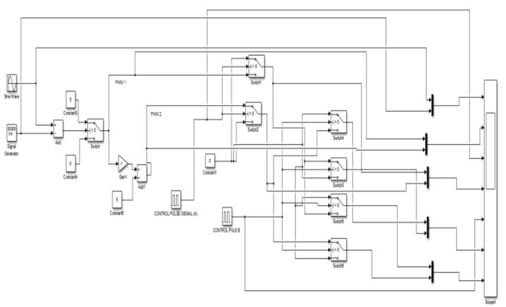
2. MATLAB SIMULATION
MATLABsimulationissystemofsimulatemodelsdesign and multi models, simulate before moving project to hardware and developing without coding and helps to predict the behavior of a system output comes there in existingdesign.Simulationtheirgeneratingthebehaviorin anenvironment.
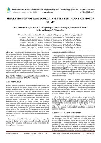
These results are obtained by simulation performanceanalyzed oversimulationofVSImodulation techniques of operation and simulation operation of a voltage source inverter and wave current, voltage, pulse generation operation are using MATLAB simulating operatinginverterandIGBTpulses.ThetotalharmonicTHD inlinephasevoltagedecreaseandcomponentincreasingthe valuesarerepresentingsimulationofvoltagecurrentwaves unipolar to bipolar conversion phase representing values techniques.
The pulse generation is a generating from six IGBT linked.Thepulsecontrollingfromthevoltagetechniquesof operatingreducingthevoltageandhisharmonicefficiency
conversion of DC source to AC conversion reducing the harmonicpulsestechniques
OperationofPWMofvoltagegenerationmainconversionof voltagemagnitudeworkingunipolarswitchingofinduction motor
PulsegeneratorIGBT
SIMULATION RESULTS OF VSI FED INDUCTION
Thisprojectobservedthatusingtheconnectionofproper switching operation of and controlling the voltage source inverterfedinductionmotoroperationofausingtheload frequency operation and using controlling the load connectionofDCsourcethereinoutputofsinusoidalwave forms in magnitude and voltage and current and load characteristicsfindwaveformsfireanglestorqueratioand directionofinductionmotor.Variousofreliableoperation application.
Inductionmotorsuchasalargetransformercapacitorand a high lighting load on the secondary the inverter which takes a variable frequency from dc supply its connected directlytoabatterymotorrotatestheoppositedirectionand calculated values their properties voltage torque and magneticvalues.
Table -1:
Thisprojectobservedthatusingtheconnectionofproper switching operation of and controlling the voltage source inverterfedinductionmotoroperationofausingtheload frequency operation and using controlling the load
International Research Journal of Engineering and Technology (IRJET) e-ISSN: 2395-0056
Volume: 11 Issue: 04 | Apr 2024 www.irjet.net p-ISSN: 2395-0072
connectionofDCsourcethereinoutputofsinusoidalwave forms in magnitude and voltage and current and load characteristicsfindwaveformsfireangleusingtorqueratio and direction of induction motor. Various of reliable operationapplication.
Induction motorsuchas a largetransformer capacitor andahighlightingloadonthesecondarytheinverterwhich takes a variable frequency from dc supply its connected directlytoabatterymotorrotatestheoppositedirectionand calculated values their properties voltage torque and magneticvalues.
SimulationofVSIcomponentofsetupthe implementingstandingsuitableoutputimproveefficiency waveformsvoltageandcurrent.
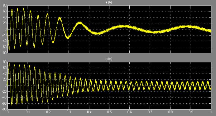
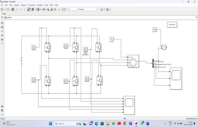
Fromthiswaveformisline ofvoltagelineandotherpulse modulationfrequencyvoltagesVabandVcavoltagerangeat 50Hzfrequencyoperationinputgivingvoltageofamplitude pulsegeneration
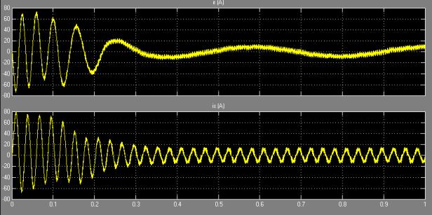
Thevariationofstatorcurrentandvoltageasanoperationof sending voltage current and come ripples of waveform of operationswitchingtransmittedand4secstatorandrotor fromthe[0.35Sec]magnitudevaluesofpulsegenerating.
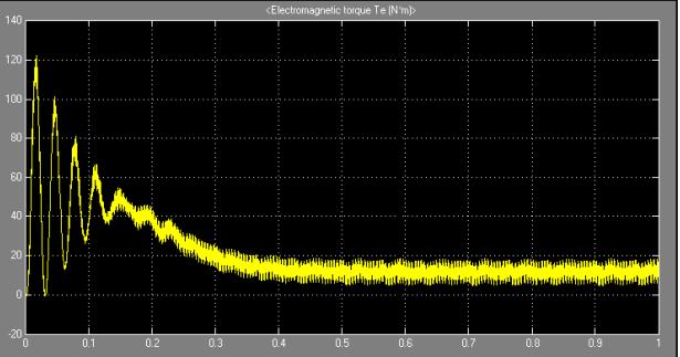
The magnetic rotor is presented by rotating speed of acceleration of normal speed to compare the different nominal speedofsituationofrotatingspeedreducingand increasingthemotor speed ofrotatingspeedofoperation magnitudeelectrostaticn-m
The value of spectrum observes that rotor and current, voltage from several techniques operation of harmonic modulation comparing the sine voltages operation of VSI modulation from higher from the input and output pulse operationcontrolled.
Thepaperpresentedbyperformanceofvoltagesourceof inverterfedinductionmotordrivesMATLABcomparethe implementation of drives and there harmonic and pulse scheme as compare the switching cover drives. Either controllingthesuddenchangingfaultsandoverincreaseand decrease the fault emission system and modulation techniques
The operation of THD and modulation operation from switchingpulsesandpowerofIGBTswitchingofsixpulse
International Research Journal of Engineering and Technology (IRJET) e-ISSN: 2395-0056
Volume: 11 Issue: 04 | Apr 2024 www.irjet.net p-ISSN: 2395-0072
generators should be controlled by the several point controllingandvaryingthevoltagesource,theoperationof the VSI fed operation compression voltage values and current, magnitude controlling they are the operated the minimumconditionoperatingtheVL linevoltageRL source current comparing the systematic line system. The rotor valueisincreaseandthedecreasetheseveraloperationsof input sending to the receiving end system modulation voltagephaselinevoltageandphasecurrentasastability.
The harmonic distribution of THD and phase voltage increasetheincreasemodulationindexvalueoperationof voltageandcurrent.
[1] M.Depenbrock,“Pulsewidthcontrolofa three-phase inverterwith non-sinusoidalphasevoltageofathreephase PWM inverter”, Proc. IEEE Int. semiconductor PowerConversionConf.,Orlando,Florida,USA,pp.399403,1977...
[2] G.Dong,“Sensorlessandefficiencyoptimizedinduction motorcontrolwithassociatedconverterPWMschemes”, PhD Thesis, Faculty of Graduate School, Tennessee TechnologicalUniversity,Dec.2005
[3] D.G.HolmesandT.A.Lippo,“PulseWidthModulation for Power Converters” – Principles and Practices, IEE Press,WileyPublications,NewYork,USA.2000.
[4] A. Iqbal, I. Lamine, Ashraf and Mohibullah,” MATLAB/Simulinkmodelforspacevectormodulation of three-phase VSI”, IEEE UPEC 2006, 6-8 Sept., New Castle,UK,Vol.3,pp.1096-1100.2006.
[5] J.Holtz,“Pulsewidthmodulation-asurvey”,IEEETrans. On Industrial Electronics, Vol. 39, No. 5, pp. 410-420, Oct.1992.
[6] G.Dong,“Sensorlessandefficiencyoptimizedinduction motorcontrolwithassociatedconverterPWMschemes”, PhD Thesis, Faculty of Graduate School, Tennessee TechnologicalUniversity,Dec.2005.