
International Research Journal of Engineering and Technology (IRJET) e-ISSN: 2395-0056
Volume: 11 Issue: 04 | Apr 2024 www.irjet.net p-ISSN: 2395-0072

International Research Journal of Engineering and Technology (IRJET) e-ISSN: 2395-0056
Volume: 11 Issue: 04 | Apr 2024 www.irjet.net p-ISSN: 2395-0072
Tejas Gami1 , Soham Gadade2 , Sahil Mhadlekar3 , Dhanraj Nagure4, Prof. Nilesh Shinde5
1,2,3.4Bachelor of Engineering, Mechanical Department, Datta Meghe College of Engineering, Airoli 5Professor, Mechanical Department, Datta Meghe College of Engineering, Airoli, Maharashtra, India
Abstract - The semi-trailing arm is an enhanced version of the trailing arm and swing axle suspension systems that balances their respective benefits and drawbacks. The semitrailing arm suspension system's characteristic parameters are identified in order to maximize an all-terrain vehicle's handling and stability performances. There are two different kinds of objective functions defined: off-line and on-line. The off-line goal function takes into account variations in the tire track, toe angle, and camber caused by roll. The handling and stability characteristics of a moving vehicle during a typical Jturn maneuver are taken into account in the online goal function. A non-linear vehicle model with nine degrees of freedom, having semi-trailing arm and double wishbone suspensions in the rear and front axles, respectively, is investigated. The optimized suspensionsystemsobtainedfrom both off-line and on-line objective functions are utilized in making two accurate vehicle models in Lotus Software for experimental field test. Acomparisonbetweenthebehaviorsof the two vehicles shows that despite the simplicity of optimization with off-line objective functions relative to online1, it returns the satisfactory results and improves both the handling and stability performances.
Key Words: Semi trailing arm, tire track, toe angle, camber, roll, degrees of freedom, Lotus software, optimization.
A multilink independent suspension system, such as the semi-trailingarmsuspension,givesthe carimproved ride controlandstability.Thesuspensionsystem'sdesignneeds toberobustevenintheworstofcircumstances.Designinga suspensionsystemwithincreasedcomfort,reducedweight, improvedhandling,increasedshockabsorptioncapability, increased vehicle stability, and reduced complexity is the majorgoal.Bytakingallofthesefactorsintoaccount,weare able to create suspension systems that are both more affordableandprovidesuperiorperformance.
This report is based on the detailed design process that TeamTorridRacingfollowsinaccordancewiththeBAJASAE Indiarulebook.TheBajasaeIndiaisanall-terrainvehicle eventheldatthenationallevel,whereteamsofengineering collegesfrom all over India participate with customdesigned and manufactured ATVs. ATVs are designed and
producedwithcompetitioninmind,meaningthattheymust be able to withstand the roughest road conditions. A vehicle's suspension system is crucial to its stability and control.Comparingsemi-trailingarmstoothertypesofrear suspension,therearenumerousbenefits.
Themainobjectivesofthedesignofthesuspensionsystem are:
Tominimizedynamiccamberandtoechangesinwheel travel to optimize the contact patch and thereby handling.
To optimize rolling characteristics by increasing roll centerheight.Thismakesthecarmoreresponsiveand this setting is ideal for tracks with quick direction changes.
To synchronize the dynamic roll center variation for frontandrearforbetterandpredictablehandling.
Tominimizetrackwidthvariationstoreduceplunging oftheshaft.
To minimize unsprung mass to have more grip in irregularterrainandtherebyimproveperformance.
•Better Handling: Propertirealignment and contact with theroadsurfacearemaintainedwiththeaidofsemi-trailing arms, which improves handling and stability of the car.
• Control of Camber and Toe Angles: During suspension travel,semi-trailingarmscanregulatethewheels'camber and toe angles to keep them within permissible bounds.
• Rear Axle Location: Semi-trailing arms assist in maintainingtheproperrearaxlepositioninginrear-wheeldrive and some all-wheel drive vehicles, guaranteeing appropriateweightdistributionandtraction.
3.1
The toe angle should be as close to zero as possible to maintainstabilitywiththeroadsurface.AslighttoegainToe gain is permissible unless vehicle’s stability is not compromised.
International Research Journal of Engineering and Technology (IRJET) e-ISSN: 2395-0056
Volume: 11 Issue: 04 | Apr 2024 www.irjet.net p-ISSN: 2395-0072
3.2 Castor angle
Since the rear tires are not equipped with any sort of steeringmechanism, the castoranglealsoissettozero at staticcondition.
3.3.1 Vertical loading
Theroadwheelexperiencestensileorcompressivevertical forces depending on the load irregularity when it encountersabumporpitinthepavement.
Calculations:
Consideradroptestwhereabuggyisunsuspendedfroma heightof6feet.
From impulse momentum equation


in meter)
2653.13 N
3.3.2 Dynamic load transfer (Cornering force)
Whenvehiclegoesthroughaturn,itfacescentrifugalforces at the Hub end of the arm. When vehicle takes a turn this centrifugalforceactsabouttheC.G.ofthevehiclewhilethe loadoppositionactstowardsthewheel.Thistendstocreate aturningcoupleactingaboutthelongitudinalaxis.
Fc=m* * =270* *


Fc =7481.5N
Fc =7481.5*0.6(rearside)
Fc =4488.9N
Fc =4488.9+(14*9.81)
Fc =4626.24N
Taking coefficient of friction of tyre into consideration ( )
Fc =4626.4*0.7
Fc = 3238.37N
3.3.3 Dynamic Load transfer (longitudinal/ Squat)
Depending on the wheel base, various suspension parameters, and the position of the center of gravity in relation to the ground, the vehicle's nose drops when the brakesareapplied.Werefertothisphenomenonasadip. Thetorqueloadsexperiencedduringaccelerationalsohave the tendency to elevate the front of the vehicle. This phenomenoniscalledasSquat.
Rdyn= *W*a

Rdyn= *270*9.81*5.55
Rdyn=5775N
Rdyn=5775* (foreachside)
Rdyn =2887.55N
Rdyn =2887.55N+(14*9.81)
Rdyn = 3024.89 N
Taking coefficient of friction of tyre into consideration ( )

Rdyn =3024.89*0.7
Rdyn =2119.423 N
3.3.4 MOTION RATIO, SPRING AND WHEEL RATE
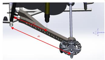
Fig -1:MotionRatio
International Research Journal of Engineering and Technology (IRJET) e-ISSN: 2395-0056
Volume: 11 Issue: 04 | Apr 2024 www.irjet.net p-ISSN: 2395-0072
Motion Ratio
Motion ratio in suspension of a vehicle system describe the amount of shock travel for a given amountofwheeltravel.
M.R= =

M.R.= 0.6
Spring rate
Spring rate refers to the amount of force that is neededtocompressaspringbyonemillimeter.
DenotedbyKs.
Rear=19.62N/mm (bymanufacturer)
Wheel rate (Kw)
Kw =KS *M.R.2* A.C.F.
Kw=19.62*0.62*1 (A.C.F.=1forrear)
Kw =7.1N/mm

Sprung mass natural frequency ( ) =

WhereKS=springrate
Andmf=frontsprungmass = =1.97Hz

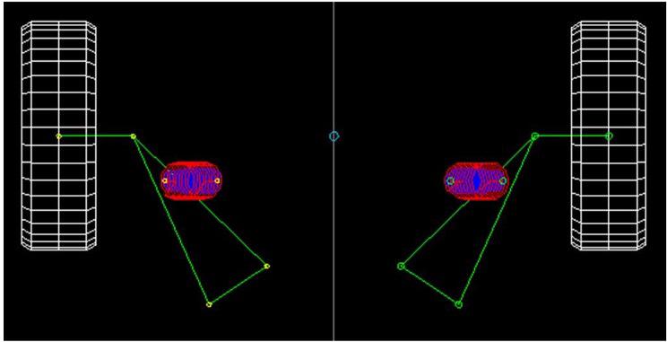
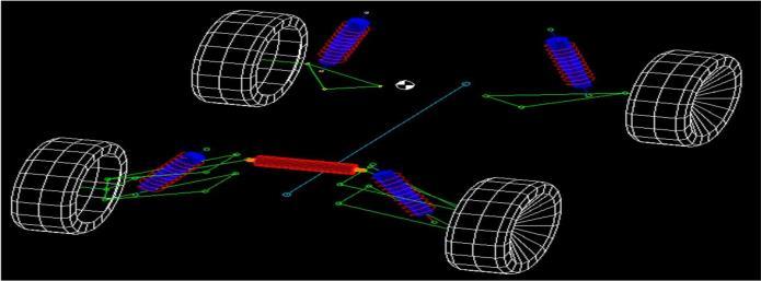
4. LOCATING THE SUSPENSION GEOMETRY IN LOTUS SHARK SOFTWARE
Inthissoftware,weneedtofillupsomepre-determineddata likedesiredC.G.height,tyre specifications,dampertravel, wheelbase.
Then by selecting the desired suspension system for e.g. Semi-trailing Rear suspension system, we can start the procedureoflocatingthehardpoints(wheelside)andthe softpoints(chassisside).
After obtaining all the chassis and knuckle points these points are to be traced at a CAD software in our case, we usedSolid-worksbyDassaultsystem.
Bytracingthepoints,a3Dmodelismadewithrespecttothe interferencewiththeBrakecalliperandthehubdiscthrough assemblyfeature.
Several iterations are done and some few are selected for furtherAnalysispart.
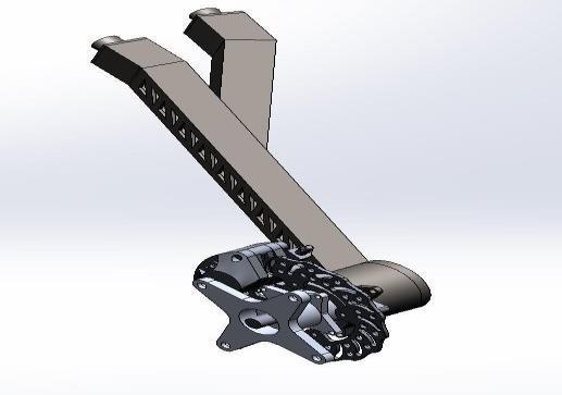
Al 7075 T6 was selected as the material of our hubs and uprightafter comparison with other alloys. It was further anodized to reduce the crack propagation. square pipe of AISI4130withside30mmandwallthicknessof3mmfor semi-trailingarm.
International Research Journal of Engineering and Technology (IRJET) e-ISSN: 2395-0056
Volume: 11 Issue: 04 | Apr 2024 www.irjet.net p-ISSN: 2395-0072
andthecomponentofforcesofalldynamicloadtransferare providedatthewheelside.
Table-1: MaterialPropertiesofSuspensionComponents
The G-force range selected is from 2G to 5G for various conditions
Static structural and fatigue analysis: These analyses were performed on A-arms, semi trailingarm,tierod,mounts,bothuprights,hubs.
Random vibration analysis:Thisanalysisgave usa frequency response spectrum which helped us in decidingthestiffnessoftheshocks.Wehavetherefore found that the AFCO shocks perfectly fit our requirement.
Topology optimization: Hubs, uprights and mounts were analysed and material was removed from low stressconcentrationregion.Thisalsohelpedinreducing theweight.
Semi-Trailing Arm
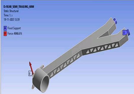
Fig -5:SemiTrailingArmBoundaryConditions
The analysis is done in Ansys Workbench, where the boundaryconditionssetareFixedatthechassispivotpoint
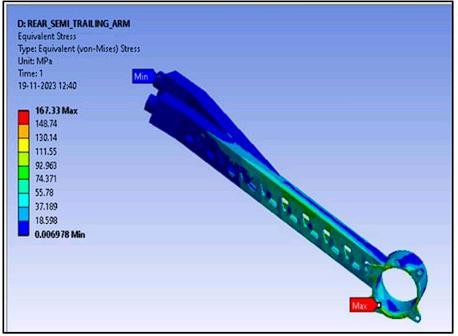
Fig -6:SemiTrailingArmEquivalentStress
Theelementtypeis3DandHexdominanttypeofmeshis used. The element size is of 3mm. We have performed various iterations with relatively higher and lower size elementbutwefoundthissizeasnexttoaccurate.
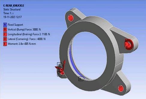
-7:UprightBoundaryConditions
Thefacewherethe bearing will befittediskeptfixedand forces and moment are applied at the ears of the knuckle wherethebrakediscandarmwillbemounted.
International Research Journal of Engineering and Technology (IRJET)
Volume: 11 Issue: 04 | Apr 2024 www.irjet.net
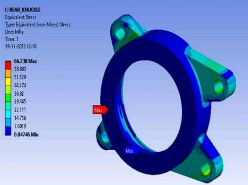
The element type is 3D linear and Hex dominant type of mesh is used. The element size is of 2mm. We have performedvariousiterationswithBoundaryconditionswith respecttovariousdrivingconditions.
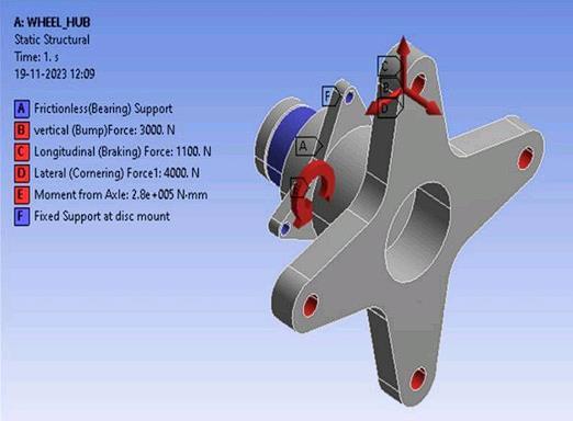
-9:WheelHubBoundaryConditions
ThefaceonwhichtheUprightbearingwillbefittediskept as Frictionless support, the wheel mounting points are appliedwiththeDynamicforces.TheDiscmountingspokes areopposedbythelongitudinalloadtransferandBraking torque.
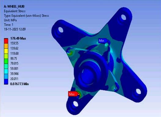
Asyoucanseethatthemaximumstressisbeenshownatthe brake disc mounts, this is due to stress singularity which meansthatwherethereislessresistingareathemagnitude ofstressismore.Butinactualconditionthereisnoharmat that mount at all, it is strong enough to sustain braking momentandDiveforce.
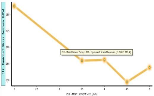
-1:Elementsizev/sEquivalentstress
properties
Table-2: Meshproperties(Ansyssoftware)
8. RESULTS Suspension Geometry Results
Table-3: SuspensionGeometryResults
Table-4: StructuralAnalysisResults(Ansyssoftware)
International Research Journal of Engineering and Technology (IRJET) e-ISSN: 2395-0056
Volume: 11 Issue: 04 | Apr 2024 www.irjet.net p-ISSN: 2395-0072
Thedesign,analysis,andintegrationofthesemi-trailingtype suspension system of an all-terrain vehicle (ATV) are covered in this study. This paper's main goal was to determine a vehicle's design parameters by a thorough analysisofvehicledynamics.SoftwaresuchasLotusShark, SolidWorks,andAnsyswereutilizedtoobtainmoreprecise and clear results of the parameters that were created to meet high accuracy and minimize any kind of unusual circumstances.For off-road conditions, the suspension systemdesignmentionedaboveisthemostdependableand safest.After200hoursofrigoroustesting,wehavenotyet observedanyvehiclebreakdowns.Withsuchanapproach, engineerscancomeupwiththebestpossibleproductforthe society.
[1] William F. Milliken, Douglas L. Milliken, “Race Car VehicleDynamics”,SAEInternational,1994.Milikenand Miliken
[2] KirpalSingh,“AutomobileEngineering”,Vol1,Seventh Edition,StandardPublishers,NewDelhi,15thEdition 2017
[3] Thomas D. Gillespie, “Fundamentals of vehicle dynamics”,SAEInternational,1992.
[4] IshanHiremath,AvantiNalawade,JaiPatil,SwarupPatil, Riteshkumar Patil, Swapnil Ugalmugale “Design and Development of Semi Trailing Arm Suspension Systemfor an Off-Road Vehicle” InternationalJournalofResearchin Engineering,ScienceandManagementVolume-3,Issue7,July-2020
[5] BAJA SAEINDIA 2024: 2024 Collegiate Design Series BajaSAEINDIA®Rules
[6] ReimpellJ,StollH,BetzlerW. The automotive chassisengineering principles, 2nd edn. Oxford: Butterworth Heinemann,Elsevier,2001.
[7] AttiaHA.Dynamicsimulationofa vehiclewithsemitrailing A-arm suspension. Trans CSME 1996; 20(2): 175–186.
[8] DixonJ. Suspensiongeometryandcomputation.Hoboken, NY:JohnWileyandSons,2009


Mr. Tejas Devji Gami
BachelorofEngineering, StudentofMechanicalDepartment,Datta Meghe College of Engineering, Airoli, NaviMumbai.
Mr. Soham Nitin Gadade
BachelorofEngineering, StudentofMechanicalDepartment,Datta Meghe College of Engineering, Airoli, NaviMumbai.
Mr. Sahil Vijay Mhadlekar
BachelorofEngineering, StudentofMechanicalDepartment, Datta Meghe College of Engineering, Airoli,NaviMumbai
Mr. Dhanraj Chandrakant Nagure BachelorofEngineering, StudentofMechanicalDepartment,Datta Meghe College of Engineering, Airoli, NaviMumbai.
Prof. Nilesh Limbraj Shinde Professor in Mechanical Department, Datta Meghe College of Engineering, Airoli,NaviMumbai.