
International Research Journal of Engineering and Technology (IRJET) e-ISSN:2395-0056
Volume: 11 Issue: 03 | Mar 2024 www.irjet.net p-ISSN:2395-0072
International Research Journal of Engineering and Technology (IRJET) e-ISSN:2395-0056
Volume: 11 Issue: 03 | Mar 2024 www.irjet.net p-ISSN:2395-0072
S. Daniel1 , Mr. S. Prakash2, R. Muthukrishanan3, S.S. Saran4, J. Vivyan Paul5
2Assistant Professor, Department of Mechatronics, Sri Manakula Vinayagar Engineering College, Puducherry,India 1,3,4,5 UG-Student, Department of Mechatronics, Sri Manakula Vinayagar Engineering College, Puducherry, India
Abstract - The Two-in-One CNC machine stands at the forefront of machining innovation, seamlessly integrating pen plotter and milling (laser engrave) functionalities within a single, space efficient unit. This cutting-edge technology optimizes manufacturing processes, reduces operational costs, and enhances workflow agility. Precision and versatility converge, delivering unparalleled efficiency for industries seeking advanced solutions in a compact and user-friendlypackage.
Key Words: CNC,LaserEngraving,Pen,Gcode,Inkscape
In industries, where machines can be demonstrated automatically. This whole process, which is made and works with the human mind, no need for any human interactionforfurtherproductionisknownasAutomation. Similarly in this Two in One CNC machine, we need to upload G-code for the process after uploading the code it performs plotting by itself. The main reason for reviewing is to evaluate existing methodologies and its efficiency to make a pen plotter which reduced the cost under fewer circumstances. After reading this paper there will be a clear understanding of pen plotter with laser engraving and it helps to guide you to build a pen plotter with laser engraving machine. The working principle of Computerized Numerical Control (CNC), which the activities are self-regulated based on the G-codes entered. The working of a plotter and other components used in buildfor pen plotter withlaser engravingare explained in furthertopics.Sincetheremustbegivenequalimportance for mechanical design, hardware, and software implementationthetopicsarealsoframedbasedonit.
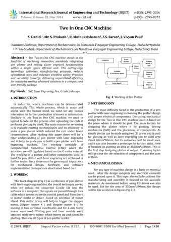
The block diagram (Fig 1) as a reference of pen plotter withlaserengravingmachine,theoveralltechniqueworks, when we upload the converted G-code file into the softwareinacomputer,thesignalsarepassedthroughdata cablewhichconnectedtothecontrolpanelandfromthere to motor shield or driver, based on selection of motor shield. This motor driver will help to trigger the stepper motor, Stepper motor X-1 and Stepper motor Y-1 for moving in two cartesian coordinates and for Z-axis Servo motor were used. Writing pen and laser module were attached with servo motor which moves up and down for plotting.Thiswayalltypesofpenplotterworks.
The main difficulty faced in the production of a pen plotter withlaser engraving ischoosing theperfect design and proper electrical components. Discussing mechanical design for the Two in One CNC machine must it based on the place where it should be plot. The main factors for designing the plotter where it be plotting, driving mechanism (belt) and the placement of components. As simpleplottercanbemadeusingtwoCDdrivesanditused for plotting as well as laser engraving can be used area about 80mm*80mm, but its outcome could be small area, and it can also become a prototype for further tasks. Here it focusses on plotting an area of 350mm*350mm. This is the first step designing plotter of output. Upcoming topics will be clear for the selection of components and the uses ofthem.
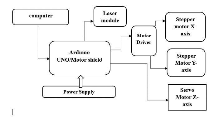
Foranytypeofmachine,designisa basicoressential need. After the design complete any electrical elements canbe placeduponit. This topic alsoincludesactionslike manufacturing and assembly. It focused on the available materials. As mentioned before, using CD drives can also be used. But for the area of 350mm*350mm, the design willbelikeasshowninfiguresFig2,3.
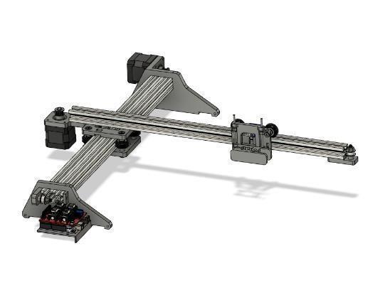
We can infer from the above image that plotters equipped with laser engraving will be removed. While the output paperbaseinFigure2isfixed,inFigure3,thebaseplateto which the sheet is to be connected moves in accordance with the movement of the pen frame. The kind of mechanism that is employed also differs. A lead screw mechanism or a beltdriven mechanism with a pulley is utilized to move along the axis. The belt is less expensive thantheleadscrewandmaybeusedmoreeasilytoadjust locations as compared to the screw. Nonetheless, the lead screwisthegreatestoptionforextremelyaccuratecontrol and the application of large loads. Aluminum, acrylic, plastic, and wood can be purchased from stores or found online to construct the outside frame. For the outside frame, it is preferable to use accessible material for low cost and good efficiency. Inner components, such as rods andattachments,canbeboughtoncetheoutsideframehas been fixed according to design and the movement mechanism. It is advisable to choose these maintenance and drawing parts with a slightly more sophisticated mindset. The purpose of side rods is to prevent vibration or rotation from disrupting the pen frame while it is sliding. A spring should be used to secure the plotting or pen frame so that it can move freely. Fixing motors and wires should be easy to shift around in order to minimize noise. Thesearethemechanical design divisions,andthey canalsobeusedtoproducehighperformance.Butpicking the appropriate pen for scheming is equally important. Testingtypicallyusesa0.7mmballpointpen,thoughother sizes can be utilized as well. laser usage 200–250 mW at 650nm.
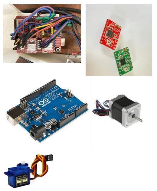
Motors are the first electrical component to be selected, followed by the kind of driver and a controller. Mechanical design is the basis of the motor selection process. The motorsare selected depending on the torque needed to rotate after the weight of the design is determined for each motor. Nema 17 hybrid stepper motors, which have a 1.8degree step angle and can hold torqueof4.2kg-cm,canbeusedforbothaxiscontrolinthe majority of circumstances. This motor only produces strong torque at 12 volts. It will be beneficial to use differenttorquesteppermotorsforvariousaxesdepending ontheweighteachoneiscarrying,butbothmusthavethe samestepangle.Thenextstepistochooseamotortohold the pen and move it up and down at the appropriate angles. The SG-90 servo motor, with its 2.5 kg cm torque and 180-degree rotation, can do this. Considering that the selection and use of motors are complete. The driver can be selected based on how the motor operates and is controlled. In that regard, the ideal combination for any CNCapplicationistheArduinoCNCshieldV3.0andA4988 stepper drivers for PWM signal control. L293D is feasible even with a stepper motor running on a TB6600, but this shield might be more swift and small. When it comes to choosingacontroller,theArduinoUNOisgreatforthisuse case. Additionally, CNC shield repairs on Arduino flawlessly.AlthoughRaspberryPicanalsobeusedinplace ofArduino,ifextrataskssuchdatascanningandsavingare completed, then Raspberry Pi 3 should be used. It is also possible to swap out Arduino with a Raspberry. There are othercontrollersaswell,suchastheMach3andMSP430, which are more expensive and primarily intended for demanding applications. It can be used as a motor driver andhasaseparateinterfaceforprogramming.TheMSP430 runs at a low voltage of 3.5 volts and requires an RS232 connectionforcommunication.
Volume: 11 Issue: 03 | Mar 2024 www.irjet.net p-ISSN:2395-0072
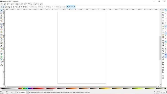
Inessence,G-codeisthelanguageusedtocommunicate with this CNC machine. Without these serial connectors, USB ports, parallel ports, and Ethernet cables, this kind of computer-to-hardware communication is not feasible. Coming is just a kind of function that regulates where the tools are positioned. Other codes, such as M-codes and Tcodes for usage with other CNC machines, are also available. These G-code files contain vector graphics that specify the machine's movement in terms of x, y, and z coordinates. Simply drag and drop the needed image or document into the appropriate program to create any of these works. For the majority of the conditions, Inkscape software is utilized as a G-code converter. Opening the program and making a few configuration adjustments such as adjusting the sheet's area or scaling to millimeters arethefirststagesintheconversionprocess. Adding libraries is particularly important. After that, position the text or picture file and adjust the scaling. Simplysavethefileinexampleformatafterthat.Codeand upload using the controller that is tied to the IDE. Download and execute the GRBL library for Arduino UNO. Forthelattersteps,useGRBLsoftware.Here,thevectorfile willbeplottedwhentheconvertedfileissubmitted.Figure Fig 5 is about how the software Inkscape appears and its logo.
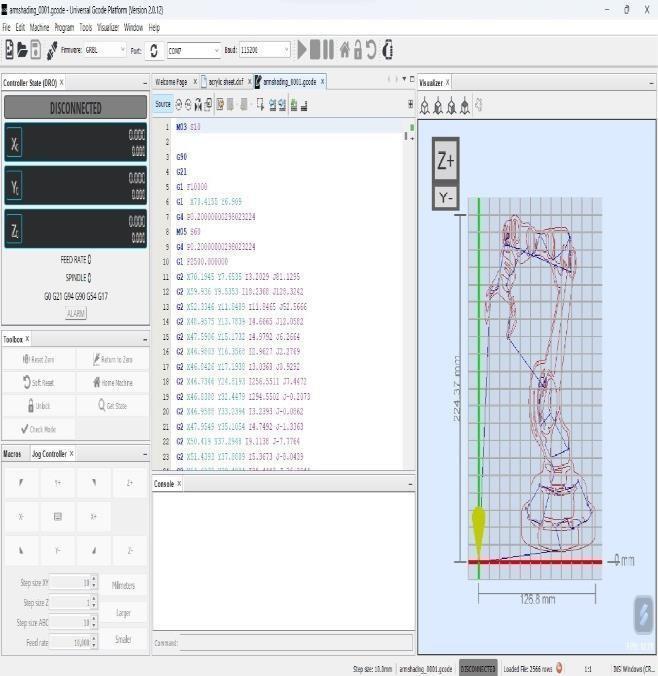
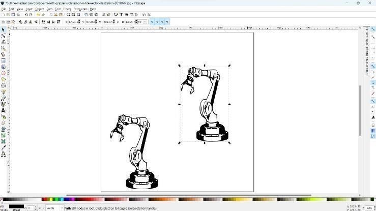
Other programs that can be used include Mach 3 for loadingthe G-codeintheevent thatthecontrollerisMach 3, Lazy CAM for generating. Code, and Coral Draw for converting files. A unique program called Parallel port driver and a session profile called Mach 3 Mill are needed forthis.Drawingbasicfigures,suchassquares,isessential after installing any program. You should also measure the sizeoftheplottedpicturebecauseitchangesdependingon the input. The only way to fix this is to experiment with differentsteppermotorrotationtimestofindtherightone. Figures 6, 7 and 8 display a small number of plotted graphs.
For newcomers, creating a pen plotter will be simple andtime-consuming byconsultingthethemescovered. As previously mentioned, the pen plotter will function properly if the input files are converted to G-code and uploaded into the controller. This study does not address
International Research Journal of Engineering and Technology (IRJET) e-ISSN:2395-0056
Volume: 11 Issue: 03 | Mar 2024 www.irjet.net p-ISSN:2395-0072
theusageofthismachineforotherpurposes,suchaslaser cutting or PCB designing, because its primary focus is on thedevelopmentofpenplotters,theirtechniques,andcost reduction through component selection. These tasks are alsoabletobecompleted.
[1] JayanandenMReviewon"BuildingaCostEfficient Pen Plotter" International Research Journal of EngineeringandTechnology(IRJET)OCT2020
[2] V.P. Srinivasan, Abhilash Arulvalan, J. Amarnath, L. Dhinesh, R.B. Dhivyan, F. Mohammed Rizwan, A. Navashanmugam, P. Mowyanivesh on "Design and fabrication of dual axis writing machine"Received 26 October 2020, Revised 7 December 2020, Accepted 14 December 2020, Available online 6 February2021,VersionofRecord3June2021.
[3] Sheetal N.Patil, Prashant G. Patil on "Implementation of Arduino UNO based Two Directional [2D] Plotter" International Research Journal of Engineering and Technology (IRJET) MAR2019
[4] Mori M, YamazakiK, Fujishima M, Liu J, Furukawa N. A study on development of an open servo system for intelligent control of a CNC machine tool. CIRP Annals-Manufacturing Technology; 2001.247-250.
[5] AnjanahD,AasthaKaushal,AnimeshGautam,Arun Kumar G "CNC Plotter Machine" International Research Journal of Engineering and Technology (IRJET)2022
[6] R.R. Jegan, E. Gnanasundaram, M. Gowtham, R. Sivanesan and D.Thiyagarajan, "Modern Design and XY Plotter," 2018 Second International Conference on Inventive Communication and ComputationalTechnologies(ICICCT),2018
[7] Shinde,Umesh&Somalwar,Rahul&Kale,Namesh & Nandeshwar,Ashish & Mendhe, Antariksh. (2020). Short paper on CNC based PCB milling machine considering human safety. Journal of ResearchinEngineeringandAppliedSciences.
[8] Aneeta Pinhiero, Beljo Jose, Tinsemon Chacko, Nazim TN, “Mini CNC Plotter” in international journal of innovative research in electrical, electronics, instrumentation and control engineeringvol.4,issue4,April2016.
[9] Y. M. Hasan, L. F. Shakir and H. H. Naji, "Implementation and Manufacturing of a 3-Axes Plotter MachinebyArduinoandCNCShield,"2018
International Conference on Engineering Technology and their Applications (IICETA),2018
[10] M.Bhavani, V.Jerome, P.Lenin Raja, B.Vignesh, D.Vignesh, Designand Implementation of CNC Router, International Journal of Innovative ResearchinScience,Engineeringand Technology, Vol.6,Issue3,March2017