
ANALYSIS OF TOOL WEAR IN TURNING OPERATION OF ALUMINIUM
Mr. Nagesh N. Yamul 1 , Mr. Gangadhar P. Hulsure 2
1 Lecturer in department of mechanical engineering, S.E.S. Polytechnic, Solapur.
2 Lecturer in department of mechanical engineering, S.E.S. Polytechnic, Solapur
Abstract - The research focuses on analyzing tool wear during turning operations on aluminum using High-Speed Steel (HSS) tools. The primary objectives are to determine the specific speed, feed, and depth of cut that minimizes tool wear when working with aluminum parts and HSS tools. Additionally, the study aims to identify the maximum and minimum levels of wear on the HSS tool at different cutting speeds. The experimentsinvolvevaryingcuttingparametersto collect data on tool wear, and the results are analyzed to provide insights into optimizing machining conditions for extended tool life and enhanced efficiency in aluminum turningprocesses. The research has practicalimplications for industries seeking to improve tool performance in machining aluminum materials.
Key Words: Tool wear, Tool geometry, Aluminium machining, High-stress conditions, High-temperature conditions, Tool failure.
1.INTRODUCTION
Theturningoperationisafundamentalmachiningprocess widelyemployedforshapingvariouscomponents,withthe primaryuseofasingle-pointcuttingtool.Inthiscontext,a diverserangeofcuttingtoolsisavailable,eachcharacterized by distinct geometries and materials tailored to machine differentmetalsandalloys.Aluminium,extensivelyutilized inautomotive,construction,andaerospaceindustriesdueto its lightweight and corrosion-resistant properties, is a commonmaterialofinterest.Cuttingtoolsundergosevere rubbingduringmetal-to-metalcontactwiththeworkpiece and chip, operating under high-stress conditions and elevatedtemperatures.Thesituationisexacerbatedbythe presenceofextremestressandtemperaturegradientsnear thetool'ssurface.Whilecuttingtoolsplayacrucialrolein removingmaterialtoachievethedesiredshape,dimensions, andfinishduringcuttingoperations,wearinevitablyoccurs, leadingtotoolfailure.Regularreplacementoftoolsoredges becomesnecessarywhenwearreachesacriticalextentto ensurecontinuedandeffectivecuttingaction.Thisresearch aims to explore the dynamics of tool wear during turning operations on aluminium, focusing on optimizing cutting parameterstomitigatewearandenhancethelongevityof cuttingtools.
1.1 Aim
Theaimoftheresearchistoanalyzeandunderstandtool wearduringtheturningoperationofaluminumusingHighSpeed Steel (HSS) tools. The overarching goal is to gain insights into optimizing cutting conditions for enhanced efficiencyandprolongedtoollife
1.2 Objectives
1. Specific Parameter Identification: Determinespecific combinationsofcuttingparameters,includingspecific speed, feed rate, and depth of cut, that result in the leasttoolwearwhenworkingwithaluminumpartsand HSStools.
2. Wear Analysis at Different Speeds: Investigateand quantify the maximum and minimum levels of wear occurringonHSStoolsatvariouscuttingspeedsduring theturningoperationofaluminum.
Theseobjectivescollectively aimto contributevaluable knowledgeforimprovingtheperformanceanddurabilityof cutting tools in the machining of aluminum components, withpotentialapplicationsinindustriessuchasautomotive, construction,andaerospace.
2. LITERATURE REVIEW
Thamizhmanii S. et al. [1]haverecoveredthatthesurface roughness from various tests shows a drop-off in value at highercuttingspeedandthefeedrate.Thecuttingtoolhas producedmicrochippingandhasnotimpressedthesurface finish.Microcrackswereacquiredfromtheborderofmicro chipping. The notch wear might have been caused due to difficult particles and other impurities existing in the material. There is no placement of built- up- edge that is normally occurring during machining cast iron at lower cutting speed. Advance work can be carried in the way of measuringtheresidualstressesbyturningandplacementof built-upedgeunderhighspeedmachining.
Ozel Tugrul et al. [2]havedeliberatedthattoolnosedesign affects the surface finish and productiveness in the finish hardturningprocesses.Surfacefinishingandthetoolflank wearhavebeenanalyzedinfinishturningofAISID2steels (60 HRC) using ceramic inserts. Twofold linear regression models and neural network models are formulated for predicting surface roughness and the tool flank wear. In neural network modeling, measured forces, power and specificforcesareusedintrainingalgorithm.Experimental
International Research Journal of Engineering and Technology (IRJET) e-ISSN: 2395-0056 Volume: 11 Issue: 01 | Jan 2024 www.irjet.net p-ISSN: 2395-0072 © 2024, IRJET | Impact Factor value: 8.226 | ISO 9001:2008 Certified Journal | Page287
***
resultspointthatthesurfaceroughnessvaluesasdegraded as0.18–0.20µmisattainablewiththewipertools.Toolflank wearreachingtoatoollifestandardvalueofVBC=0.15mm ahead or around 15 min of cutting time at higher cutting speedsduetoelevatedtemperatures.
Omar B. Bin et al. [3] have observed that wear pattern depend on the CBN tools used, work piece material composition, and cuttingconditions.Theyalsoconcludedthatgenerally,adhesion, abrasion and diffusion are reasoned to be main tool wear mechanismsinCBNhardturning:however,theindividualeffect ofeachmechanismdependsonthecombinationsoftheCBNtool and workmaterials,cuttingconditions,tool geometryetc.Afew elementary mechanisms rule cutting tool wear are: 1. Diffusion wear smittenbychemical loadingontool and cuttingmaterial2. Oxidation wear - crusades gaps to occur in coated film and outcome in a loss of the coating at elevated temperature, 3. Fatigue wear - is a thermo-mechanical result and leads to the breakdownoftheedgesofcuttingtool,4.Adhesivewearhappen at devalued machining temperatures on the chip face of tool and leadstoshapingofabuiltupedge,andtheperpetualbreakdown of the built up edge and tool edge itself, 5. Abrasive wear affected by hardness of the work material and is restrained by content of the cutting material.
Lin H.M. et al. [4]havefoundthattoollifeemergeswiththe gain of cutting speed until a supreme is reached where it startstodrop-off.Inalow-levelspeedcutting,abrasionisthe firsthandformofwear.Whencuttingspeedisaugmented,a stickinglayeriseffectedandstaysontoolfacewhichprevent toolfacefromwearing.Atgraduatecuttingspeed,thechipis exchangedfromcontinuoustypetosaw-toothtype.Friction forceisinflatedconsequently,andthelayerontoolfaceis abrasedbitbybit.Sincescatteringbetweenworkandthetool materialsturnmorethanintenseathighercuttingspeed,the bond 'tween the hardparticles isvitiatedand wear onthe rakefaceisexaggerateddrastically.
Kamarudin K. et al. [5]havediscoveredthatFlankwearin the ceramic cutting tools is mechanically stained wear ordinarily by the abrasive state of the hard work piece materialwithceramictools.Theflankwearischaracterized bytheabrasivegrooveandelevationontheflankface.The flankwearofthecuttingtoolhasamomentousresultonthe attribute of the machined surface. Flank wear has a prejudicialeffectonthesurfacefinish,residualstressandthe micro structural changes, shape of tool, as well cutting conditions.Thefloodingtemperaturebringforth'tweenthe cuttingfaceandworkpiecejustifiesabrasiveandoradhesive wear.Thesetypesofwearimpactthetoolmaterialsattribute aswellasworkpiecesurface.Thereasonsforgaininflank wearwereduetoincreaseintemperatureatthecuttingedge duetomoreinteractiontimebetweentoolandworkpiece. Thetemperaturemaycausingtoloseitshardnessandwear. Whenthecuttingspeedwastakedown,theflankwearwas takendownandastheseparametersareaccrued,theflank wearalsoexaggerated.
Vikas B. Magdum, Vinayak R. Naik. [6]intheirpaperused the cutting forces in a turning process of EN 8 steel to estimatethetoolweareffect.Toolweareffectisobtainedby
monitoringthevariationinthecuttingforces.Theintentof thisstudyis todevelopan on-line observationsystem. By distinguishing one or more than one criteria to efficiently specifyanddeterminerapidtoolwear,itcanbeascertained when to change the tool. the correlation between the tool wear and cutting forces shows that, the cutting forces are increasedasthetoolwearincreases.
Nithyanandhan.T T, Manickaraj.K and Kannakumar.R [7] in their study, an endeavor has been made to analyze the result of cutting parameters on the cutting forces and the tool wear in the hard turning of AISI 304 steel using the coatedcarbidetools.Theresultsrevealedthatthefeedand noseradiusisthealmostimportantprocessparameterson workpiecesurfaceroughness.Evenso,thedepthofcutand feedarethesignificantfactorsonMRR.
S. Thamizhmnaii, B. Bin Omar, S. Saparudin, S. Ha [8] haveconductedresearchtoexhibittoolwearwiththehelp of hard turning of martensitic stainless steel and this materialisarticulatedasdifficulttomachinematerial.The judgment wasdoneutilizing CBN cuttingtoolonSS440 C stainless steel with hardness between 45 to 55 HRC. The flankwearoccurredatlowcuttingspeedwithhighfeedrate and more depth of cut i.e. at cutting speed of 125 m/min, feed rate of 0.125 mm/rev and DOC of 1.00 mm. The influence of tool flank wear was due to abrasive action betweentooltipandcuttingtool,hardcarbidesinthework piecematerial.Atlowcuttingspeedof125m/min.formation ofbuiltupedgewasinevitableduetomorecontacttime.The flank wear was also due to heat generated at low cutting speed
Ning Fang, P Srinivasa Pai & Nathan Edwards [9] have analyzedtool-edgewear(i.e.,thewearofatoolcuttingedge before it is meagerly worn away) is among momentous concerns in high-speed machining because it can effect in early tool failure and decayed quality of machined parts. Foundedonextensiveexperimentaleffect,thispaperdisplay howtool-edgeweariscorrelativewiththecuttingforcesand vibrationsinhigh-speedturningofInconel718.Astool-edge geometryshowaimportantroleinmachiningatsmallfeed rates,tool-edgewearimportantlycontributestoprimaltool failureandcrumbledqualityofmachinedcomponentsand parts.
Pramod Kumar N.et al. [10]intheirpresentwork which involvethestudyofthermalandwearbehavioroftooland work interface. Experiments were conducted on a Turn master 35 automatic lathe. Different cutting forces, temperatureoftooltip,thicknessandtheweightofthechips settledduringmachiningalongwithtoolwearinformation werecanned.Thecausationofthecuttingparameterswas deliberated.Basedontheresearchdataplotsareacquired. The mild steel turning procedure provided some helpful resultsinabstractiontomachiningparameters,whichwill be utile in developing turning process improvement with respecttopowerconsumptionandtoollife.
International Research Journal of Engineering and Technology (IRJET) e-ISSN: 2395-0056 Volume: 11 Issue: 01 | Jan 2024 www.irjet.net p-ISSN: 2395-0072 © 2024, IRJET | Impact Factor value: 8.226 | ISO 9001:2008 Certified Journal | Page288
3. Research Methodology
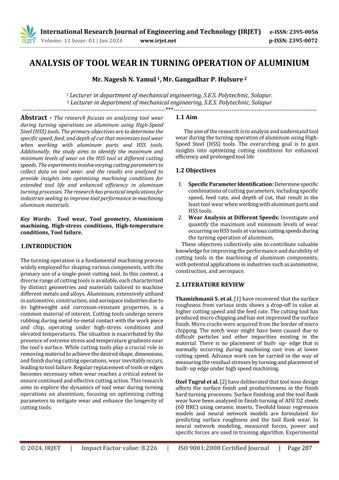
AHMTLT20makelathewasusedforturningexperiment. Thedynamometerismountedontoolpostwiththehelpofa holderspeciallydesignedforthisexperimentalwork.Then the actual experiments have been carried out with the differentinputcuttingconditionsfordifferentexperiments forconstantvolumeofmaterialremovalineachcase.
Theexperimentscarriedoutaresummarizedas:
1.CarryoutexperimentonlathemachineusingAluminium asworkpieceandHSSturningTool.
2. Machining is done with different sets of Cutting speed, depthofcut,&feedrates.
3.Measuringthecuttingforceswithdynamometer.
4.MeasuringtheflankwearoftheHSStoolwithmicroscope.
5. Observing the wear trends in SEM. The flank wear is measured and value of cutting forces is given by dynamometer.Thesevaluesofflankwearandcuttingforces areplottedagainstcuttingspeedtoobtaintheweartrends.
4. RESULTS AND DISCUSSION
ThepresentproblemthatisAnalysisoftoolwearinturning operationofAluminiumhavebeendevelopedinaccordance withthepreviouslydevelopedmodelsfortoolwear[1],[3] and[5].Thenumberofexperimentshasbeenconductedto findoutthecuttingforcesandflankwearofthetool,madeof HSStool,atvaryingmachiningparameters,whicharecutting speed (v), cutting feed (f) and keeping depth of cut (d) constant. Using this data various graphs are plotted and analyzed.Alsocuttingtoolwearbehaviorisobservedusing SEMaftervariouscuts.
MACHININGPARAMETERSUSEDFOREXPERIMENTATION:
Cutting speed v (rpm)(Range)
Feed f (mm/rev) (Range)
Depthofcutd (mm)(Range)
198,295,431,634 0.05,0.11,0.22,0.45 0.4(constant)
Table1:Cuttingparameters
The table 1 shows the numerical values of the various machiningparameters(cuttingspeed,feedandthedepthof cut), that have been selected for experimentation, for the measurement of cutting forces and flank wear. The Aluminium work-piece material has been used for experimentation. The cutting material used is High speed steel tool. The table 2 shows the experimental values of wear,andcuttingforcesfordifferentspeed,feedanddepth ofcutsforthedifferentsetofexperimentsconductedonthe
HSScuttingtool.Total16experimentswereconductedand depth of cut is kept constant in all the experiments. To eliminate the effect of wear on the experiments, the tools have been replaced after every cut of constant volume of work-piecematerial.Intotal16HSScuttingtoolhavebeen usedforallthedifferentsetofexperimentstobeconducted. Tooledgehasbeenmadestraightorparalleltothechuckto haveanorthogonalcut.Theexperimentswereconductedfor constant volume. Constant volume signifies that equal amountofmaterialwasremovedinallthedifferentsetsof experiment conducted. This has been done so that all the measurements should be taken correctly at the same operatingconditionstohaveagoodaccuracyinresultswith minimumpossibleerror
Table2:ExperimentalResultsofmeasuredparameters againstparametersV,fandd


International Research Journal of Engineering and Technology (IRJET) e-ISSN: 2395-0056 Volume: 11 Issue: 01 | Jan 2024 www.irjet.net p-ISSN: 2395-0072 © 2024, IRJET | Impact Factor value: 8.226 | ISO 9001:2008 Certified Journal | Page289
Fig.1.MachineSetup
Sr. No. Cutting Speed v(rpm) Feed f (mm/r ev) Depth of cut d (mm) Fx (N) Fz (N) Flank Wear (µm) 1 198 0.05 0.4 19.4 14.7 0 2 198 0.11 0.4 24.5 19.6 28 3 198 0.22 0.4 34.3 29.4 0 4 198 0.45 0.4 14.7 9.8 96 5 295 0.05 0.4 39.2 24.5 23.6 6 295 0.11 0.4 107.9 49 72.5 7 295 0.22 0.4 68.2 53.9 8.5 8 295 0.45 0.4 39.2 63.7 52.4 9 431 0.05 0.4 29.4 9.8 45.2 10 431 0.11 0.4 19.6 24.5 62.5 11 431 0.22 0.4 14.7 19.6 26.5 12 431 0.45 0.4 49 78.5 83 13 634 0.05 0.4 44.1 24.5 65 14 634 0.11 0.4 24.5 39.2 43 15 634 0.22 0.4 63.7 68.6 92 16 634 0.45 0.4 53.9 58.6 55.4
Fig2.Work-pieceaftermachining
Fig3.HSStoolsaftermachining
VALIDATION:
Inordertocheckthevalidityoftheresultsvariousgraphs areplottedbetweenCuttingSpeedandForcecomponents (Fx and Fz) and between Cutting Speed and Flank Wear. These plots are compared with the results given by ThamizhmaniiS.[1],forcheckingthevalidityofresults.The resultsfromthereferencearewellinaccordancewiththe resultsofthepresentwork.
VARIATIONOFVARIOUSFORCESWITHCUTTINGSPEED:


International Research Journal of Engineering and Technology (IRJET) e-ISSN: 2395-0056 Volume: 11 Issue: 01 | Jan 2024 www.irjet.net p-ISSN: 2395-0072 © 2024, IRJET | Impact Factor value: 8.226 | ISO 9001:2008 Certified Journal | Page290
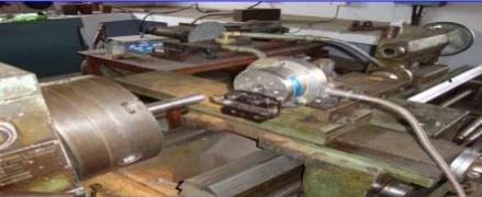
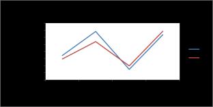
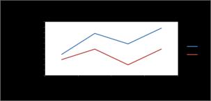
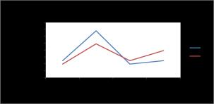
Fig.4.1to4.4showsthevariationofforceswithcutting speed
Fig.4.1CuttingSpeedVsForcesat0.05Feed
Fig. 4.2 Cutting Speed Vs Forces at 0.11 Feed
Fig. 4.3 Cutting Speed Vs Forces at 0.22 Feed
OFFLANK
CUTTINGSPEED:
Fig. 4.4 Cutting Speed Vs Forces at 0.45 Feed
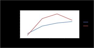
VARIATION
WEARWITH
Fig.4.5CuttingSpeedVsFlankWearat0.05Feed
Fig.4.6CuttingSpeedVsFlankWearat0.11Feed
Fig.4.7CuttingSpeedVsFlankWearat0.22Feed
Fig.4.8CuttingSpeedVsFlankWearat0.45Feed

CUTTINGFORCES
There are two cutting forces which are acting on a single point tool in orthogonal cutting (Fx and Fz) The Fx is the feed force which is acting on the X direction and Fz is the cutting force acting on the Z direction. The cutting forces were measured using 3 component dynamometer (Force measurement dynamometer).The figuresaboveshow the variouscuttingforcesmeasuredduringturning.Thecutting forceFzwaslowwhencuttingatfeedof0.05and0.11andat cuttingspeed198and431rpmwhereasthefeedforceFxis low at the start and increased when the cutting speed increased.ThefeedforceFxandcuttingforceFzismaximum at295and431rpmcuttingspeed.
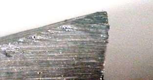
TOOLWEAR(FLANKWEAR)
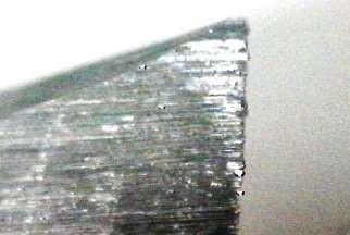
Theflankwearisawidelyusedcriterionforevaluatingtool life because of its importance in most applications. Flank wearisproducedmainlyduetoabrasivewearofthecutting edge against the machined surface. The flank wear in this experiment was not present when machining at 198 rpm cuttingspeedandat0.05mm/revfeed,thenincreasedto 65µm at 634 rpm speed having same feed rate. But flank wear96µmobservedatspeed198rpmhavingfeedof0.45 mm/rev.Inotherexperiments,theflankwearwaslessthan 150µm. Fig. 6.10 show flank wear at 634 rpm and 0.22 mm/revfeedandfig.6.11showsflankwearat295rpmand 0.45mm/revfeed.Thetwomaineffectsareresponsiblefor toolwearareoxidationofthetoolandinterdiffusionofthe constitutingelementsbetweentoolandworkpiece.Fig.6.9 showsflankwearsurfaceat431rpmand0.05mm/revfeed. Hardparticlesploughgroovesintothecuttingtoolmaterial. Excessivenotchwearaffectssurfacefinishandweakensthe cutting edge. Fig. 6.13 shows notch wear at 198 rpm and 0.45mm/revfeedrate


International Research Journal of Engineering and Technology (IRJET) e-ISSN: 2395-0056 Volume: 11 Issue: 01 | Jan 2024 www.irjet.net p-ISSN: 2395-0072 © 2024, IRJET | Impact Factor value: 8.226 | ISO 9001:2008 Certified Journal | Page291
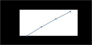
Fig.4.9VariationofFlankWearwithCuttingSpeed
Fig.4.10MicrographshowsFlankWearat634rpmand 0.22mm/revfeed
Fig.4.11MicrographshowsFlankWearat295rpmand 0.45mm/revfeed
Fig.4.12MicrographshowsFlankWearat431rpmand 0.05mm/revfeed
Fig.4.13MicrographshowsNotchWearat198rpmand 0.45mm/revfeed
5. CONCLUSION
The analysis of experimental results yields several noteworthy conclusions regarding the turning operation undervaryingcuttingconditions.Firstly,itisobservedthat cuttingforcesexhibitsignificantlylowervaluesatacutting speedof431rpmforallfeedrates,withtheexceptionofa feedrateof0.45mm/rev.Thetangentialfeedforce(Fx)at this particular feed rate demonstrates a consistent increasing trend across different cutting speeds. Additionally,atlowercuttingspeeds,flankwearisfoundto be zero for feed rates of 0.05 mm/rev and 0.22 mm/rev. However,themaximum observedflank wear,reaching 96 µm, occurs at a speed of 198 rpm with a feed rate of 0.45 mm/rev. Notably, the flank wear at feed rates of 0.05 mm/revand0.22mm/revexhibitsaconsistentincreasing trend,whilethecombinationofafeedrateof0.11mm/rev and a cutting speed of 295 rpm results in maximum flank wear, showing a decreasing trend. These findings provide valuableinsightsintotheintricateinterplaybetweencutting speed,feedrate,andresultingforcesandwear,facilitating informeddecisionsforoptimizingmachiningparametersto enhance tool performance and overall efficiency in the turningprocess
REFERENCES
[1] S. Thamizhmanii, S. Hasan, “Analyses of roughness, forces and wear in turning gray cast iron”, Journal of Achievements in Materials and Manufacturing Engineering,Vol.17(2006),pp.401-404
[2] TugrulOzel,YigitKarpat,LuisFigueira,J.PauloDavim, “Modelling of surface finish and tool flank wear in turning of AISI D2 steel with ceramic wiper inserts”, Journal of Materials Processing Technology, Vol. 189 (2007),pp.192–198
[3] S. Thamizhmnaii, B. Bin Omar, S. Saparudin, S. Hasan, “Toolflankwearanalysesonmartensiticstainlesssteel by turning”, Archives of Materials Science and Engineering,Vol.32(2008),pp.41-44.
[4] H.M.Lin,Y.S.Liao,C.C.Wei,“Wearbehaviorinturning high hardness alloy steel by CBN tool”, International JournalofWear,Vol.264(2008),pp.679–684
[5] S Thamizhmanii*, K. Kamarudin, E. A. Rahim, A. Saparudin,S.Hassan,“ToolWearandSurfaceRoughness in Turning AISI 8620 using Coated Ceramic Tool”, ProceedingsoftheWorldCongressonEngineering,Vol. II(2007).
[6] Farouk Mahfoudi, Gautier List, Lakhdar Boulanouar, “High speed turning for hard material with PCBN inserts: tool wear analysis”, International Journal of MachinabilityofMaterials,Vol.3(2008),pp.62-79
[7] J.A.Arsecularatne,L.C.Zhanga,C.Montross,“Wearand tool life of tungsten carbide, PCBN and PCD cutting tools”, International Journal of Machine Tools & Manufacture,Vol.46(2006),pp.482–491
[8] Yong Huanga, Ty G. Dawson, “Tool crater wear depth modelinginCBNhardturning”,InternationalJournalof Wear,Vol.258(2005),pp.1455–1461.
[9] L.J. Xie, J. Schmidt, C. Schmidt, F. Biesinger, “2D FEM estimate of tool wear in turning operation”, International Journal of Wear, Vol. 258 (2005), pp. 1479–1490
[10] J. Lorentzon, N. Jarvstrat, “Modelling tool wear in cemented-carbidemachiningalloy718”,International JournalofMachineTools&Manufacture,Vol.48(2008), pp.1072-1080.
BIOGRAPHIES


Mr. Nagesh N. Yamul
Lecturer in S.E.S. Polytechnic, Solapur.Graduatedinmechanical Engineering and did masters in Manufacturing Process from Solapur University, Solapur and havingexperienceofmorethan11 yearsinteaching.
Mr. Gangadhar P. Hulsure, Lecturer in S.E.S. Polytechnic, Solapur.Graduatedinmechanical Engineering from Solapur University, Solapur and having experienceofmorethan14years inteaching.
International Research Journal of Engineering and Technology (IRJET) e-ISSN: 2395-0056 Volume: 11 Issue: 01 | Jan 2024 www.irjet.net p-ISSN: 2395-0072 © 2024, IRJET | Impact Factor value: 8.226 | ISO 9001:2008 Certified Journal | Page292