
International Research Journal of Engineering and Technology (IRJET) e-ISSN:2395-0056
Volume: 11 Issue: 12 | Dec 2024 www.irjet.net p-ISSN:2395-0072


International Research Journal of Engineering and Technology (IRJET) e-ISSN:2395-0056
Volume: 11 Issue: 12 | Dec 2024 www.irjet.net p-ISSN:2395-0072
By Farid Akhtar Khan, India
Abstract
This paper presents an in-depth case study on the defective construction of a pile foundation and its remedial measures. Typically, projects do not anticipate defects severe enough to impact the project timeline, nor do they allocate time for defect analysis,designrectification,preparationofdrawingsandrepairing.Insuchascenario,itbecomesessentialtoadoptexpedited processes for defect analysis and solution for remedial works. This paper provides critical insights in to identifying and remediatingdefectsinboredcast-in-situpileconstructionataprojectsiteinUttarakhand,India.
Keywords
Pilefoundation,BoredCast-in-situ,Lowstraintest,Highstraintest,Statictest,Piledraft
Introduction
Case study is for the defects encountered during the construction of pile foundation for the main plant RCC building, which measures 31m x 37 m in size and is of 35 m in height with multiple levels of equipment-supporting floors. A piled raft was conceptualized and designed with a group of 340 piles. Due to lose silty soil at the bearing level, the raft’s contribution to the foundationcapacity wasnot considered.Eachpilewas 600mmin diameterand 18m inlength. Poorconstruction supervision and inappropriate construction methods were practiced at site and that led to the complex situation where everything was uncertain about the integrity of piles and pile capacity. The client reviewed the field inspection report closely and raised concernsaboutwhethertheconstructedfoundationachievedtheintendeddesignstrength.Theclientdirectedtheprojectteam to perform a thorough quality check of piles, certify their adequacy and provide design and drawings for corrective measures. Thiscasestudycomprehensivelydetailstheentireprocessencompassingdefectanalysis,theformulationofmitigationdesigns andtheexecutionofremedialmeasures.
1. Reviewandanalysisoftheconstructedpilefoundationtoidentifythequalityissues
2. Review of the existing geotechnical investigation report to assess soil conditions and their implications on the pile foundation
3. A Cost and time-optimized sequential approach for defects analysis using low-strain integrity testing, and evaluate capacitythroughhighstraindynamictesting.
4. Reassessandredesignthepiledraftfoundation,incorporatingproposedmodificationstotheoriginaldesigntoachieve thedesignstrength.
5. Recommendsuitablecorrectivemeasuresforimplementationtorestorethefoundationfortheintendeddesignloads
6. Conclusionsandlessonslearnt.

International Research Journal of Engineering and Technology (IRJET) e-ISSN:2395-0056
Volume: 11 Issue: 12 | Dec 2024 www.irjet.net p-ISSN:2395-0072
NGL:219.90m
Pilecutofflevelasperdesign:216.90m
Pilebottomterminationlevel:198.90m
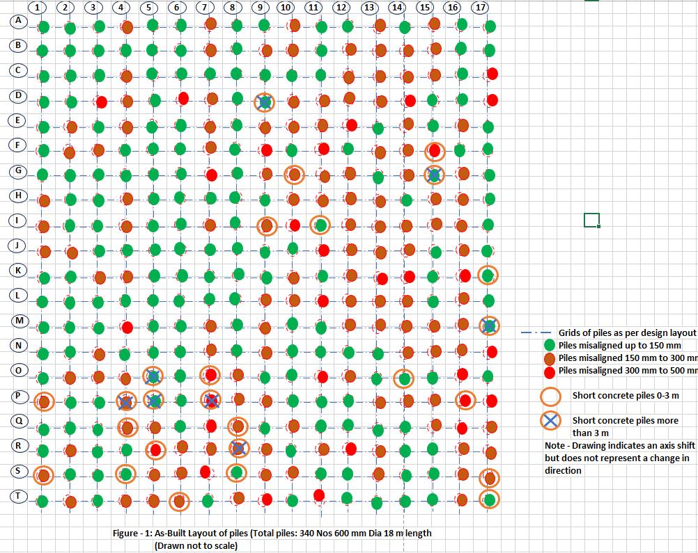
Defects observed through visual inspection:
1. Shortconcreteinpiles.
2. Misalignmentofpiles’location
3. Reinforcementbelowcutofflevelofpiles
Pilesmisalignedupto150mm-181Nos
Pilesmisaligned150mmto300mm-129Nos
Pilesmisaligned300mmto500mm-30Nos
Morethan90%ofthepilesweremisaligned.
ShortConcretedPiles(1mto2m):14Nos
ShortConcretedPiles(2mto3m):4Nos
ShortConcretedPiles(morethan3m):8Nos
AsperIS2911,Pilesshouldnotdeviatemorethan75mmorD/6whicheverislessfromtheirdesignedpositionsatthe workinglevel.
© 2024, IRJET | Impact Factor value: 8.315 | ISO 9001:2008 Certified Journal | Page355

International Research Journal of Engineering and Technology (IRJET) e-ISSN:2395-0056
Volume: 11 Issue: 12 | Dec 2024 www.irjet.net p-ISSN:2395-0072
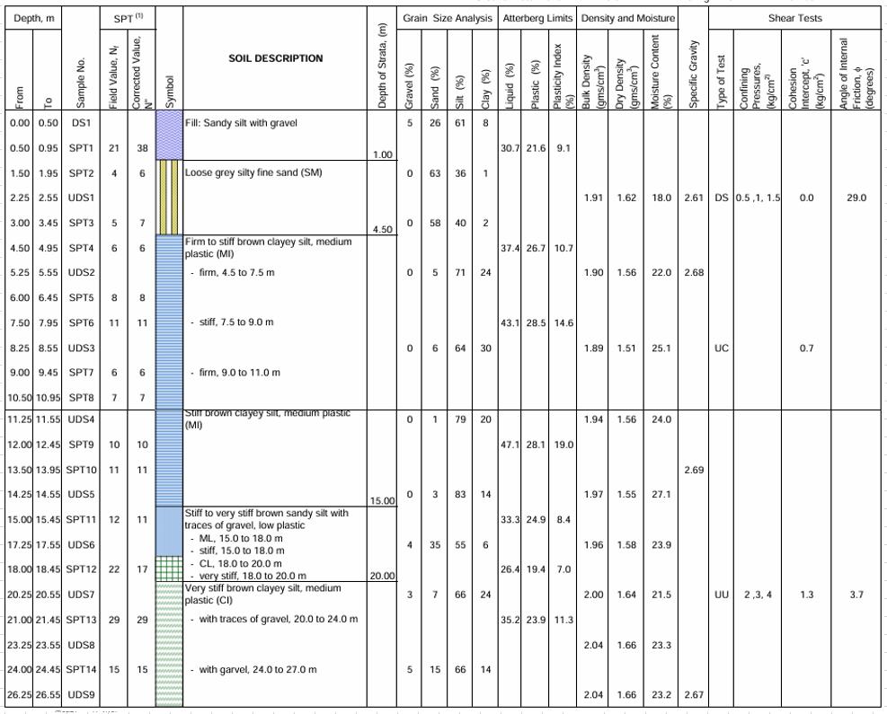
Geotechnical data have been collected from the existing geotechnical investigation report, and the geotechnical conditionsofthebuildingsitecanbesummarizedasfollows:
Asurficial fill ofsandysilt wasencountered toabout1 mdepth.Below this,the natural soilsconsistofloose siltyfine sand to about4.5mdepth.Belowthis,sandysilt/clayeysiltisencounteredtoabout29.0mdepth.Thisisunderlainbysiltyfinesandto thefinalexploredof30m.
Itisimportanttonotethatlaboratorytestprogramforsoilstrengthassessmentofthevariouslayers werenotsufficient.Only twodirectsheartest,threeunconfinedcompressiontestsandtwoundrainunconsolidatedtriaxialtestswereperformedwhich arenotsufficienttocalibratethesoilstrengthassessmentthroughfieldtestsi.e.SPTN-values.Inabsenceofsufficientlabtests data fordrainedandundrainedsoilstrengthassessment, pile capacitycalculationsin thesoilinvestigation data, largely depend upontheSPTN-values.
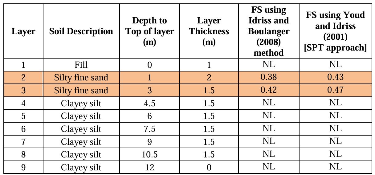
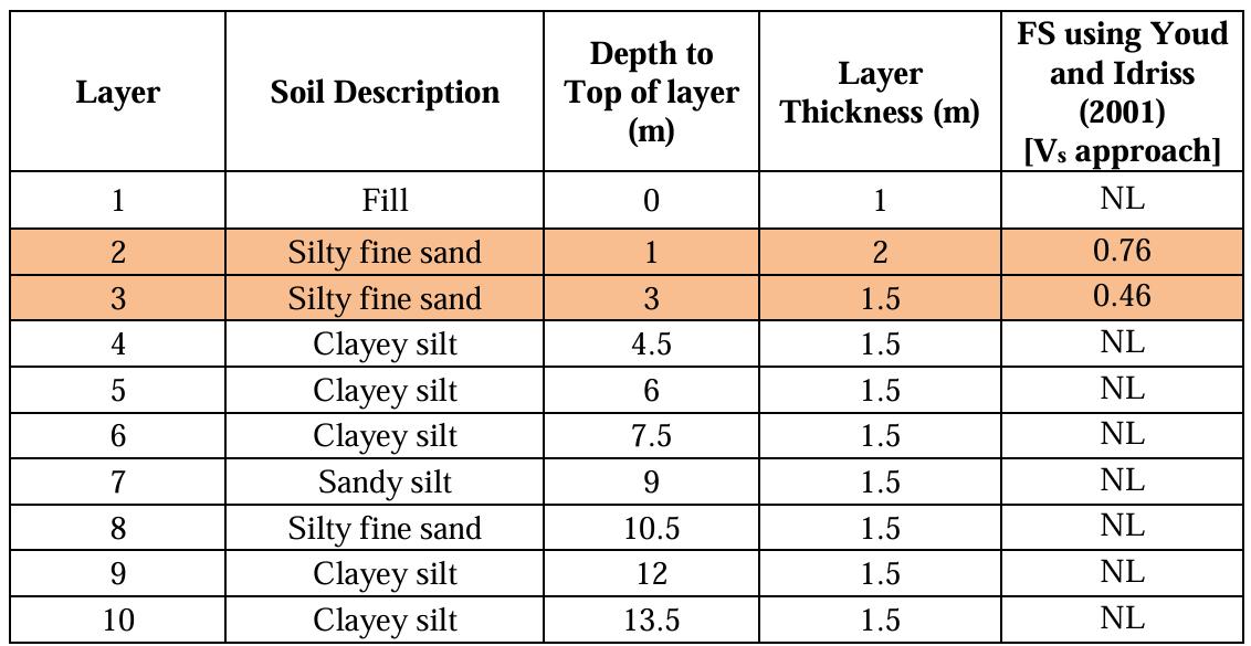
TheliquefactionpotentialforthesitewascalculatedbysimplifiedprocedureasgivenbySeedandIdriss(1971),asdescribedin NCEERSummaryreport[YoudandIdriss(2001)]andit wasfoundthatthesoilupto4.5 mdepthispronetoliquefactionfor the selected data of earthquake. IIT Bombay is of the opinion that the sub soil available at site is predominantly silt and clay havingfinescontentmorethan35%(seeFig2.3).Hence,thementionedprocedureofYoudandIdriss(2001)forevaluationof liquefactionpotentialshouldnotbeapplicableforthissite.Hence,theliquefactionsusceptibilityatpresentsiteisre-estimated by using a more correct/suitable method for fine grained soils, i.e. Idriss and Boulanger (2008) method. In addition to this, availableCross-holeSeismicTest(CHST-1)dataarealsousedtoestimateliquefactionsusceptibilitytostrengthentheconfidence levelofliquefactionpotentialevaluationforthissite.
Table1:Computedpilecapacity


International Research Journal of Engineering and Technology (IRJET) e-ISSN:2395-0056
Volume: 11 Issue: 12 | Dec 2024 www.irjet.net p-ISSN:2395-0072
designprofile

International Research Journal of Engineering and Technology (IRJET) e-ISSN:2395-0056
Table4:Liquefactinassessmentusingcrossholeseismicdata
Tests available:
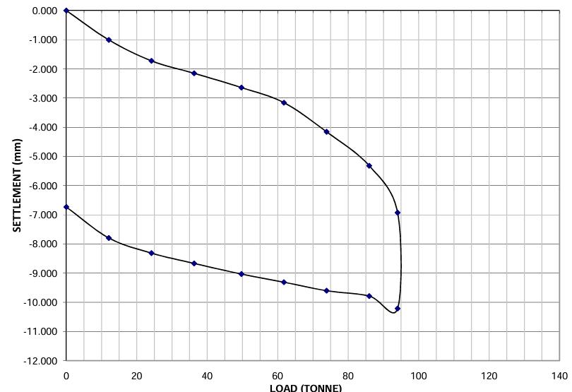
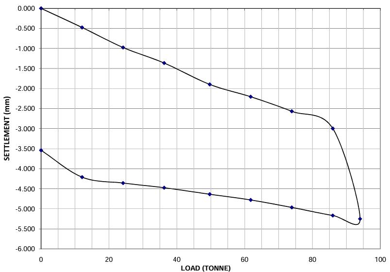
Routine Test: Routinetestswerecarriedout,whichachievedtherequiredcapacityasperIS2911Part4.Thisislikelybecause allthepilesselectedfortheroutinetestbeinggoodpiles.
Graph1:LoadvsLoadincrement(RoutineLoadTestforPileC-5)
Volume: 11 Issue: 12 | Dec 2024 www.irjet.net p-ISSN:2395-0072 © 2024, IRJET | Impact Factor value: 8.315 | ISO 9001:2008

International Research Journal of Engineering and Technology (IRJET) e-ISSN:2395-0056
Volume: 11 Issue: 12 | Dec 2024 www.irjet.net p-ISSN:2395-0072
2:LoadvsLoadincrement(RoutineLoadTestforPileI-16)
Pile Integrity Test: The graphs from the pile integrity test report were evaluated and it was found that many of them were inconclusive.
Table5:Pileintegrityreflectogramdata
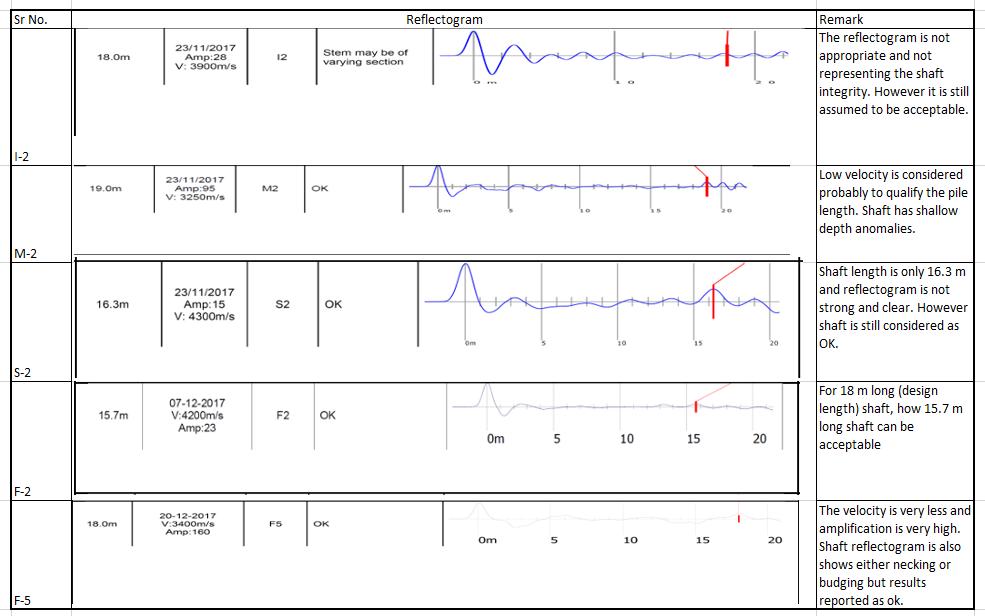
Forpileintegritytestingreport,differentamplificationlevelsareselectedfor eachpile(it’s likedifferentzoomlevel foreach picture) which is not usual and needed to be re verified. It seemed that it was carried out to identify the toe response but
© 2024, IRJET | Impact Factor value: 8.315 | ISO 9001:2008 Certified Journal | Page359

International Research Journal of Engineering and Technology (IRJET) e-ISSN:2395-0056
Volume: 11 Issue: 12 | Dec 2024 www.irjet.net p-ISSN:2395-0072
neither toe response is obvious nor signals along the pile are meaningful which may provide different conclusion for shaft response.
Initial conclusions and recommendations:
Drawingupontheanalysisofdefectsidentifiedthroughvisualinspectionandtheevaluationofexistinggeotechnicaldata,the followinginitialconclusionswereformulated:
1. Whileconstructionrecordwasalreadyavailableitwasnotclear,whyalltheroutineloadtestswereconductedonthe pileswhicharefreefromanyconstructiondefect.Itwaspossibletoconducttheloadtestsonfewofthepileshaving considerable anomalies i.e. shorter in length, pile having borehole collapse record etc. which would provide more insight of the defective piles. Presently none of the routine compressive load tests represent any defective pile. The routineloadtestprogramforcompressiveloadonlyrepresentsthehalfofthepilesofthebuilding.Itonlycoverspile markAtoJand1to17.
2. Itwasrecommendedto carryout additional routinetestsonpilesselectedfrom the defectivegroup,aswell asfrom theremainingoftheareaspanningJtoT However,giventhecriticalityof projectcompletiontimelineandthetimeconsuming nature of routine tests, high-strain dynamic load testing (HSDT) was proposed for selected piles under strictsupervisionofexpertsandallrelevantparties.
Table6:Pilesselectedforhigh-straindynamicloadtesting
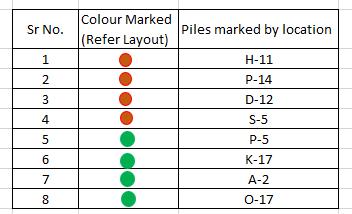
3. Itisstronglysuggestedtore-conducttheintegritytestingatleastonallthepilesinquestionunderstrictsupervision ofexpertandallpartiesinvolved.Thiswillhelptorevalidatetheproperpilelength casted,shaftintegrityandproper identificationoftheanomaliesassociatedwiththepilesinthegroup.
4. Thevalidationofpileloadtests wasrecommendedforthesitebyusingPLAXIS3Dandconventionalt-z&q-zcurves. Thesedatawillbefurtherusedforre-analyzingtheentirepilegroup.Loaddataontheindividualcolumnsupportsare tobemadeavailabletoquicklyrevisitandtakedecisionregardingaugmentationormodificationinthelayoutofpiles andraft.
5. Re-analysisconsideringtheas-builtpileconditionswastobeputonholduntilthe resultsofHSDTandlowstrainpile integritytestsbecameavailable.
6. Theoutcomesofthenewlyrecommendedtestswerecriticalforexploringremediationoptions,including:
a. Leveraging the pilecaptocompensate forthe exclusion ofthestrengthcontributionfromdefectivepiles, where uncertaintyexistedindeterminingtheirloadcarryingcapacity.
b. Anotheroptionofdesignscenariowherethepilecapshapeanddesigncanbemodifiedconsideringthechangein thepilealignment.Insuchcase,theexistenceofsomeoftheshort-concretepilesmayalsobetaken,dependingon theresultsofHSDT,whichisessential.However,incaseofanyuncertaintyinfixingthecapacityofshortconcrete piles,freshpilecastingistoberecommendedadjacenttodefectivepiles.

International Research Journal of Engineering and Technology (IRJET) e-ISSN:2395-0056
Volume: 11 Issue: 12 | Dec 2024 www.irjet.net p-ISSN:2395-0072
c. Third option was not to do any further testing but to cast additional piles adjacent to all defective piles and redesignlayoutofpilesandraft.
7. Prior to discarding the piles only based on short concrete piles (over drilling during boring lead to sinking of the reinforcement cage) or eccentricities or lack of appropriate development length for reinforcement cage was not considered to be prudent approach and it was preferred to assess the pile capacities prior to discarding defective piles.
Project activities following Initial conclusions and recommendations:
1. Lowstrainpileintegritytests:
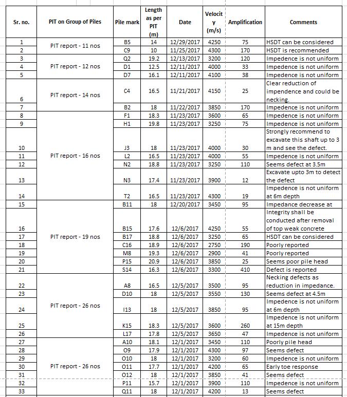
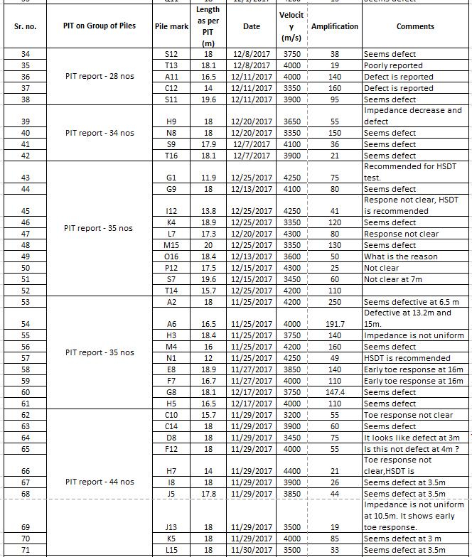
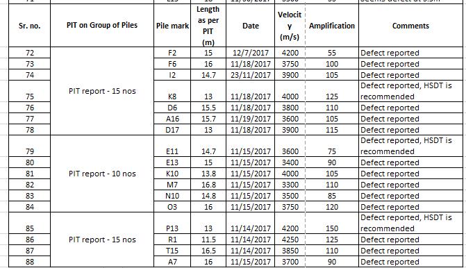
Thetestagencywasinstructedtoperformtestsonremainingpilestoachieve100%coverage.Whileitisnotfeasible topresentallthetestresultshere,anevaluationofthetestresultsforpilesinquestionispresented.(Refertable7)
Table7:EvaluationreportofPileintegritytests

International Research Journal of Engineering and Technology (IRJET) e-ISSN:2395-0056
Volume: 11 Issue: 12 | Dec 2024 www.irjet.net p-ISSN:2395-0072
Table7:Continued

International Research Journal of Engineering and Technology (IRJET) e-ISSN:2395-0056
Volume: 11 Issue: 12 | Dec 2024 www.irjet.net p-ISSN:2395-0072
Table7:Continued
Generalobservations(PITTests):
All thetest resultsindicated thatpile shaft exhibituniformintegrity,with wavespeeds forthetestedpilesgenerally ranging from 3400m/sec to 4200m/sec, which may be classified as fair concrete quality. However, 34 piles showed an early toe response,warningfurtherinvestigation.
2. High strain dynamic load testing:
A total of 8 HSDT tests were proposed in the initial conclusions report. These tests were conducted, and the results aresummarizedasbelow:
Theobtained8nos.ofHSDTtestresultssuggestthatpileofferedsufficientresistance
Table8:(SummaryofHSDTTests)


International Research Journal of Engineering and Technology (IRJET) e-ISSN:2395-0056
Volume: 11 Issue: 12 | Dec 2024 www.irjet.net p-ISSN:2395-0072
Table9:(SummaryofHSDTTests)
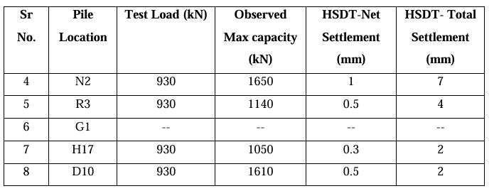
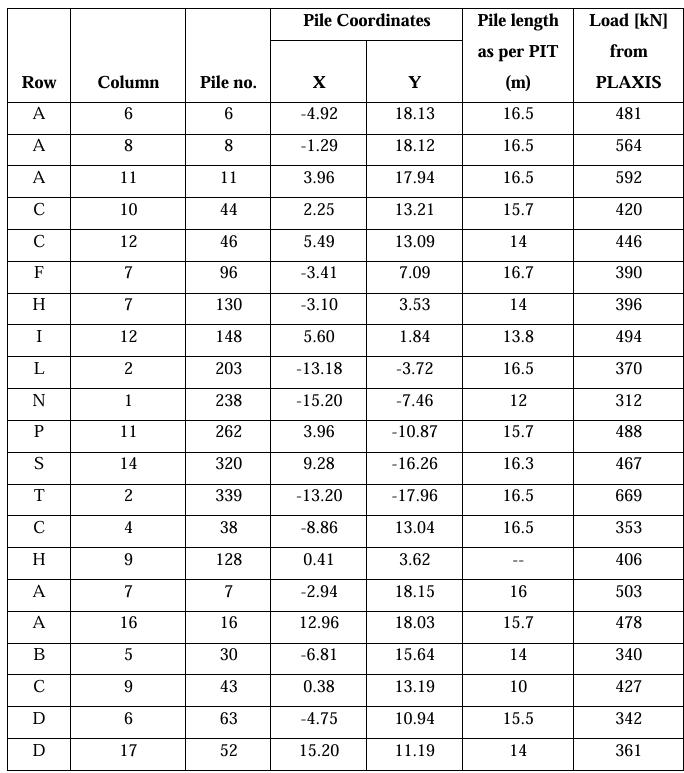
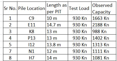
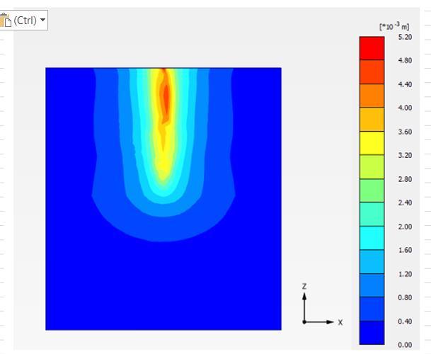
3. AsperPITtests,34pileswereidentifiedasdefectivebasedontheirearlytoeresponse.However,sincepileintegrity up to the point of toe response was found to be satisfactory, these piles could still be utilized. Pile shafts measuring 12-13 m or longer were expected to provide significant pile resistance. To identify the criticality of each pile, the forcesonthemwerecalculatedusingPLAXIS3D andsubsequentlyreviewed.Theobservedaxialloadsonthesepiles aretabulated(Table10).Pilecapacitieswerecalculatedbasedonthetoeresponselengthsofthepilesandcompared with the actual calculated loads. It was found that 5 piles were getting marginally overloaded. Therefore, It was proposedtoconductadditionalHSDTonthese5overloadedpiles,withanadditional2pilesselectedforconfirmatory testing.Testresultssuggestthatoverloadedpilesofferedsufficientresistance(Table11).
Table10:Axialloadsummaryon34defectivepiles

International Research Journal of Engineering and Technology (IRJET) e-ISSN:2395-0056
Volume: 11 Issue: 12 | Dec 2024 www.irjet.net p-ISSN:2395-0072
Table10(Continued)
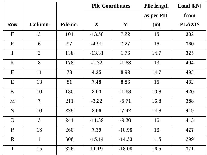
Table11:HSDTTestresultsonmarginallyoverloadeddefectivepiles

International Research Journal of Engineering and Technology (IRJET) e-ISSN:2395-0056
Volume: 11 Issue: 12 | Dec 2024 www.irjet.net p-ISSN:2395-0072

International Research Journal of Engineering and Technology (IRJET) e-ISSN:2395-0056
Volume: 11 Issue: 12 | Dec 2024 www.irjet.net p-ISSN:2395-0072

International Research Journal of Engineering and Technology (IRJET) e-ISSN:2395-0056
Volume: 11 Issue: 12 | Dec 2024 www.irjet.net p-ISSN:2395-0072
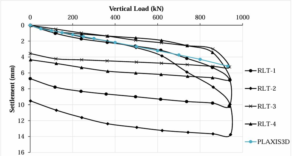
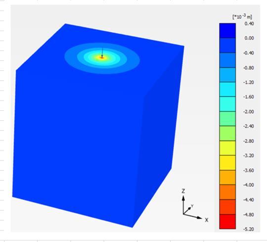
-4:ComparisonofLoad-SettlementcurveforpileobtainedthroughfieldloadtestandthroughPLAXIS3D
1. Analysis of Piles and Pile Cap:
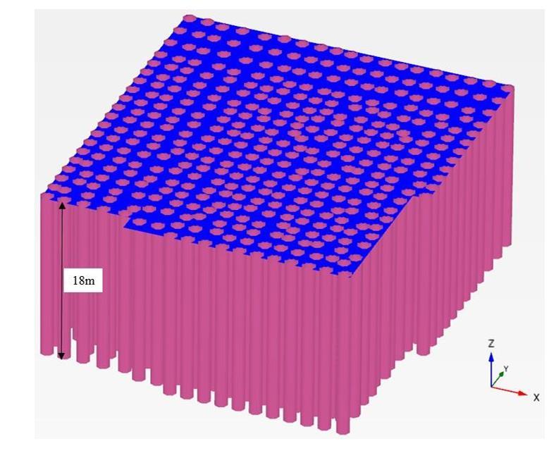
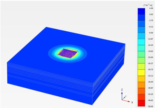
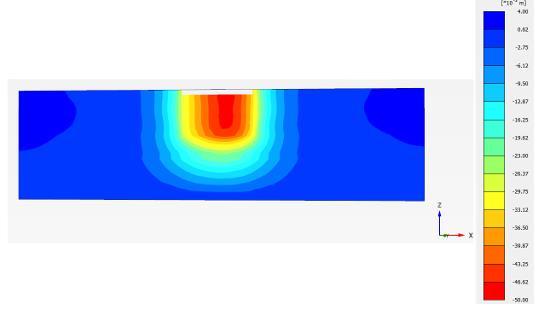
Auniform model size of200mx200m x50mismaintainedforall theanalysis.The columnloadsareappliedasthe pointloadonthepilecap.Followingstepsarefollowedwhileperformingtheanalysis
1.Developmentofsoilmodelincludingthefillsoil.
2.Excavationthemodelforplacingthepilecap.
3.Introductionofpilestothesoilmodel.
4.Placingthepilecap.
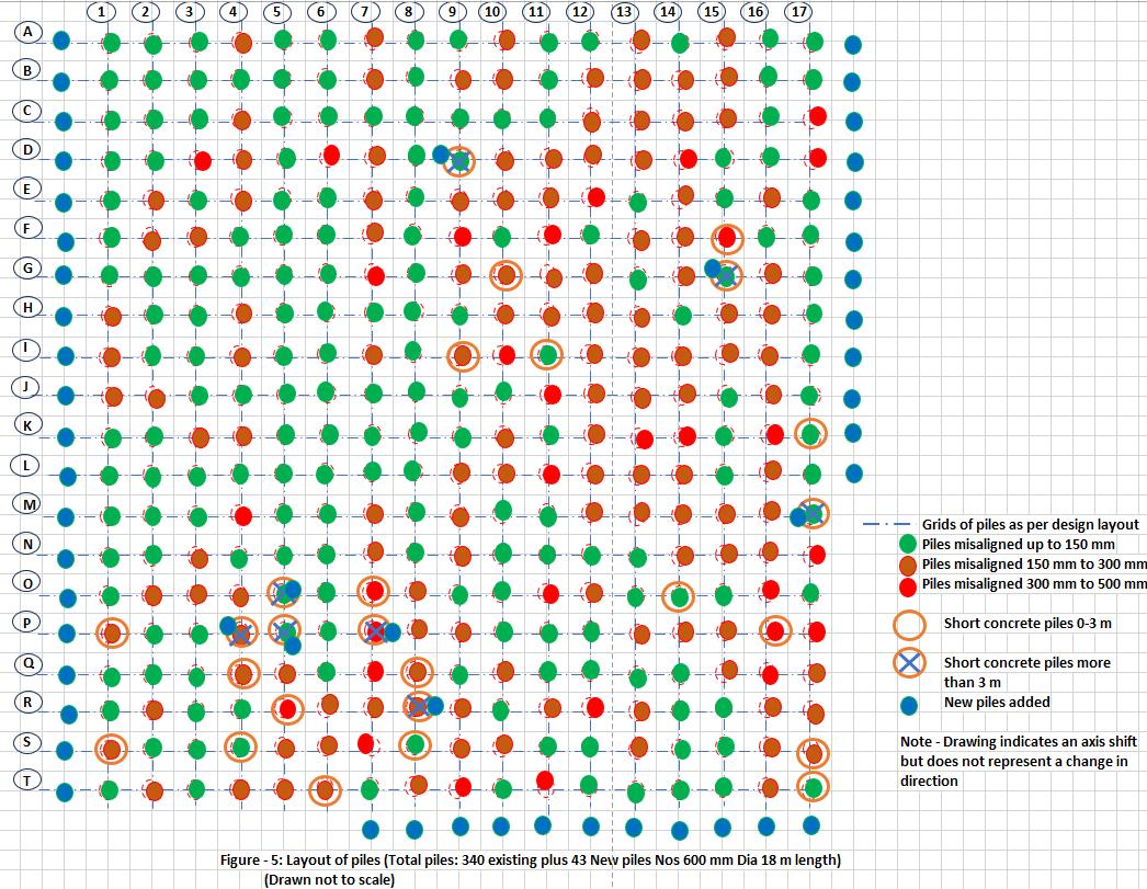
Atotal of340pilesare first modelledin PLAXIS3Dandanalysesarecarriedout. Aspilescross markedareshort concretedby morethan3m,theyareneglectedinthemodelandfreshnewadjacentpilesareconsideredintheanalysis.Itwasobservedthat theallowableaxialloadof775kN(considering25%seismicdemand)wasnotsatisfiedin22numberofpileslyingatthecorner andedgelocationofcap.Thisismainlyduetothemisalignedbuilt-inpiles.Weperformedextensiveiterationsandsuggesteda mostoptimumdesignsolutionthatis1.2mextensiononthewestsideforadding43newpiles(20pilesinwestsideofpilecap+ 12 piles in east side + 11 piles in south east side) around the periphery of the building. In addition to that 8 new piles are proposedadjacenttoexistingpiles.

International Research Journal of Engineering and Technology (IRJET) e-ISSN:2395-0056
Volume: 11 Issue: 12 | Dec 2024 www.irjet.net p-ISSN:2395-0072

International Research Journal of Engineering and Technology (IRJET) e-ISSN:2395-0056
Volume: 11 Issue: 12 | Dec 2024 www.irjet.net p-ISSN:2395-0072

International Research Journal of Engineering and Technology (IRJET) e-ISSN:2395-0056
Volume: 11 Issue: 12 | Dec 2024 www.irjet.net p-ISSN:2395-0072

International Research Journal of Engineering and Technology (IRJET) e-ISSN:2395-0056
Volume: 11 Issue: 12 | Dec 2024 www.irjet.net p-ISSN:2395-0072

Final conclusions:
1. The developed numerical model in PLAXIS3D was validated using field test results provided by the geotechnical agencyforselectedpiles.
2. Theresultsofthelow-strainpileintegritytestsresultsshowedthatpileshaftsdemonstrateduniformintegritywithin theacceptablelimits,exceptfor34piles.Thesepileswerefurtheranalyzedforaxialloadsderivedfromthemodelling of entire pile group. Axial loads were compared with the calculated capacities based on PIT test toe response shaft lengths. 5 piles were found to be marginally overloaded. HSDT load tests were conducted on these 5 piles, and the resultsvalidatedthemassafe.
3. Asthepilesselectedforroutineloadtestsconductedpriortothereportingofqualityissuessufficientlyrepresentative ofpiegroup,HSDTloadtestswereconductedon7selectedpiles Resultsvalidatedthemassafe.
4. After multiple iterations of PLAXIS 3D analysis, the most optimal, feasible, and safe design layout required the additionof43newpilesalongtheperipheryoftheas-builtpilegroup.Additionally, 8newpileswereaddedadjacent tothe8proposedcross-markedpilesthatweretodiscarded Sincethepilecaphadnotyetbeencast,itsthicknessand reinforcementweredesignedbasedontheshearforceandbendingmomentdiagramfortheaugmentedpilelayout.
5. Although short concreted piles (0-2 m) were recommended to be developed under stringent site supervision, these pileswereconsideredinthecalculationswithderatedcapacitiesequalto50%oftheiractualcapacity.
Remedial measures adopted:
1. Augmentedlayoutofpilesandpilecapwasissuedforconstruction
2. Short-concretedpiles(0-3m)wereexcavatedtothetopoftheconcreteanddevelopedtothedesiredlevelusing reinforcementcouplingandpipeshuttering
3. Short-concreted piles more than 3 m were excluded from the strength contribution, these piles were to be kept buriedinthegroundwithoutbeingconnectedtothepilecap.
4. Pile number D-15 showed possible defect at a depth of 2.5 m from the test level. It was excavated and exposed, with the poor loose concrete being chipped off. The pile was then repaired with reinforcement coupling and reconcreting.
Lessons learnt:
1. Poor construction practices, methods and a lack of stringent quality procedures led to defects in the pile’s construction. Quality control is crucial for construction projects because it can lead to increased costs, extended projecttimeline,andfailuretomeetthetargetedproductiondate.
2. The remedial measures aimed to utilize most of the as-built piles and provide solutions and recommendations promptly. Identifying and eliminating problems through sequential tests and analysis proved to be cost and time

International Research Journal of Engineering and Technology (IRJET) e-ISSN:2395-0056
Volume: 11 Issue: 12 | Dec 2024 www.irjet.net p-ISSN:2395-0072
effectiveapproach.HSDTwerequicklyconductedwithouttheneedforanyreactionarrangement.Eachtestrequired onlyonedaytoconductonetest.Theentiredefectanalysis,alongwithtestsandsolutions,tookthreemonthstimeto complete.
Conflict Of Interest
Noconflictofinterest
Funding
Nofunding
References
1.BearingCapacityofDefectiveReinforcedConcretePileinSand-modelStudybyA.M.Nasr,W.R.Azzam1and K.E.Ebeed
2.ExperimentalInvestigationonthebehaviorofadefectivepilesubjecttoalateralloadpublished:16October2021
3.IdentifyingDefectsinDeepBoredPiles-CaseStudiesfromIndiabySorabhGupta(VicePresident),CengrsGeotechnicaPvt. Ltd.,India,Email:sorabh@cengrs.com
4.TestingforMonitoringPileConstruction,Geosymposium2008,IndianGeotechnicalSocietyDelhiChapter,pp173-178
5.ASTMD4945-08,StandardTestMethodforHigh-StrainDynamicTestingofPiles
Biography

An accomplished Civil Engineer with over 25 years of expertise in leading engineering solutions for world-class industrial projects across diverse sectors, including chemical, oil & gas, FMCG, automotive, and power transmission industries. With a richtenureatesteemedorganizationslikeL&TEDRC,MottMacDonald,andIPS,Ihavespearheadedthedesignandexecution of complex technological structures and facilities. Currently serving in the Engineering Services Department at KEC International,Iamdedicatedtodrivingexcellenceinindustrialengineeringandinnovation.