

Static analysis and design of G+10 RCC framed structure by using ETABS
N. Mallikarjuna1, K. Nagendra Babu2 , Dr. G. Sivanatha reddy3, B. Keerthi4 , T. Karuna sree5
3Assistant professor (Ad-hoc), Department of civil engineering, JNTUA college of engineering Pulivendula, Andhra Pradesh, India.
1,2,4,5B. Tech(student), Department of civil engineering, JNTUA college of engineering Pulivendula, Andhra Pradesh, India.
Abstract - ETABS stands for Extended Three-Dimensional Analysis of Building Systems Static analysis in ETABS primarily involves the examinations of a structure’s behaviour under various static loads, aiming to determine its stability, strength, and deformation characteristics. It utilizes the finite element method to perform this analysis. This project presents a comprehensive study on the static analysis and design of a G+10 Reinforced Cement Concrete (RCC) framed structure employing ETABS software. The objective is to analyse the structural behaviour and ensure compliance with various design codes and standards. The study includes the modelling of the structure in ETABS, applying appropriate loads, and performing static analysis to evaluate its stability, strength, and performance under various conditions. Furthermore, the project explores the design aspects by considering factors like material properties, safety measures, and optimization techniques. The values of dead loads and live loads are taken as per [6]. Results obtained from the analysis are discussed, providing insights into the structural efficiency and integrity of the G+10 RCC framed structure designed through ETABS software.
Key Words: Static Analysis, ETABS, G+10, RCC, finite element method, static loads,
1. INTRODUCTION
Understanding the structural behaviour of high-rise constructions like G+10 buildings is paramount for ensuring their resilience. This research employs advanced ETABS software to meticulously analyse the static characteristics, investigating the stability, and deformation tendencies of this ten-story structure. By delving into the intricate details of its structural performance, this study aims to offer comprehensive insights essential for optimizing design methodologies and fortifying the safety standards of similar high-rise edificesinthefieldofconstruction.
1.1 About ETABS: ETABS specializes in performing structuralanalysis,modelling,anddesignofbuildings.Its capabilities encompass diverse functionalities, including but not limited to finite element analysis, seismic analysis, and design code compliance checks. ETABS utilized for simulating and evaluating the behaviour of
structures under various loads, enabling precise assessment, design optimization, and ensuring compliance with international building codesandstandards.
2. LITERATURE REVIEW:
k. Naga Sai Gopal and N. Lingeshwaran (2017), Inthe project they used the ETABS software due to company suggestionandtofinalstressanalysisinslab,shearforce forthebeamandareareinforcementforthecolumnand design the foundation depends upon the reaction and heightofthefoundationleveldependsuponsiteandsafe bearing capacity of the soil stability purpose designed theretainingwallinthisproject.
Puneet Mittal; Nishant kad, all structures are analyzed & designed according to code requirements using manual calculations or by the use of many different analysisanddesignsoftwarelikeSTAADPRO,ETABS.But ithasbeen foundthat it is difficulttoperform manually, so to overcome this problem analyzing and designing is donebyusingsoftwaremeantforthiswork.
3. OBJECTIVES
To carryout analysis and design of main structural elements of super structure such as slabs,beamsandcolumns.
To perform analyse the forces, bending moments, stress, strain deformations or deflectionsforacomplexstructuralsystem.
Verify building safety under various loads to preventstructuralfailures.
Ensureevenstressdistributionacrossstructural elementsforrobustness.
Enhance structural efficiency while maintaining safetystandards.
Assess building resilience in earthquakes and severeweatherscenarios.
Confirm alignment with building codes and industrystandardsforconstructionapproval.
International Research Journal of Engineering and Technology (IRJET) e-ISSN:2395-0056 Volume: 11 Issue: 01 | Jan 2024 www.irjet.net p-ISSN:2395-0072 © 2024, IRJET | Impact Factor value: 8.226 | ISO 9001:2008 Certified Journal | Page118
***
4. METHODOLOGY
4.1BUILDINGDESCRIPTION:
Buildingtype:Residentialbuilding(G+10)
Builduparea:836m2
Floorheight:3m
Seismiczone:IIzone
Importancefactor:1
Soiltype:I-Rock
Externalwallthickness:230mm
Internalwallthickness:115mm
Columnsize:450*500
Beamsize:300*450
Cover:60mm
Gradeofconcrete:35MPa
Gradeofsteel:500Mpa
Slab:150mm,Shearwall:200mm
4.2LOADDETAILS:
Floorfinishedload:1.5KN/m2
Liveload:2.5KN/m2(IS875Part2,1987)
Deadload:3.75KN/m2(IS875Part1,1987)
WallloadsonexteriorBeams:13.8KN/m2
Partitionwallloads:6.9KN/m2
Terraceload:1.5KN/m2
Parapetload:3.45KN/m2
Earthquakeload: asper1893part12016
Windloads:IS875Part32015

5. ANALYSIS RESULTS AND DISCUSSION
In the analysis results discussion, several crucial factors demand attention for comprehensive structural evaluation, Among these are overturning moments, pivotal in determining the rotational forces impacting a structure. Story shear, reflecting the maximum lateral force experienced at each building level,aids in reinforcing elements against lateral loads. Additionally, assessingmaximumstorydisplacement,highlightingthe greatestverticalorhorizontalmovementbetweenfloors during seismic or wind events, is vital. These checks collectively guide engineers in fortifying structures, ensuring stability, and safeguarding against potential damagefromvariousforces.

5.1 Maximum story displacement: Maximum story displacementreferstothegreatestverticalorhorizontal movementexperiencedbetweenfloorsduringseismicor wind events. It’s a critical parameter in structural assessment, guiding engineers to reinforce buildings against excessive movement, ensuring structural integrityandoccupantsafety.
Table:1Storyresponsevalues

International Research Journal of Engineering and Technology (IRJET) e-ISSN:2395-0056 Volume: 11 Issue: 01 | Jan 2024 www.irjet.net p-ISSN:2395-0072 © 2024, IRJET | Impact Factor value: 8.226 | ISO 9001:2008 Certified Journal | Page119
Fig:1Planand3Dviews
Fig:2LoadpatternEQ-X

5.2Maximumstorydrifts : Maximumstorydriftdenotes the greatest lateral displacement between floors during seismic or wind events. Crucial in design, it informs engineers about structural movement, aiding in reinforcement strategies to maintain stability and minimize potential damage in buildings subjected to lateralforces.


Fig:5WIND-Y
Table:2Maximumstorydriftvaluetable(WIND-X)

Table:3Maximumstorydriftvaluetable(WIND-Y)

International Research Journal of Engineering and Technology (IRJET) e-ISSN:2395-0056 Volume: 11 Issue: 01 | Jan 2024 www.irjet.net p-ISSN:2395-0072 © 2024, IRJET | Impact Factor value: 8.226 | ISO 9001:2008 Certified Journal | Page120
Fig:3Maximumstorydisplacement
Fig:4Maximumstorydrifts(WIND-X)
5.3 Maximum story shear: Maximum story shear represents the highest lateral force experienced at a building level. It’s critical in structural design, guiding engineerstoreinforceelementsagainstlateralloadslike wind or earthquakes, ensuring structural stability and safety.


5.4Overturningmoments:Overturningmoments,pivotal instructuralengineering,inducerotationalforcesaiming to topple a structure, Engineers counter these forces via foundation design, strategic structural elements, and stability considerations, crucial for preventing excessive rotationorcollapse.

Fig:8Storyoverturningmoment(W-X)
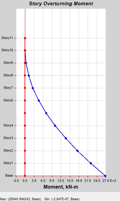
Fig:9Storyoverturningmoment
5.5 Shear force: Shear force in a building refers to the lateral force acting horizontally along the structure’s floors and walls. Analysing and designing to mitigate these shear forces are critical to ensuring the structural strengthandsafety,oftendoneusingsoftwarelikeETABS tosimulateandoptimizethestructure’sresponsetosuch forces.
International Research Journal of Engineering and Technology (IRJET) e-ISSN:2395-0056 Volume: 11 Issue: 01 | Jan 2024 www.irjet.net p-ISSN:2395-0072 © 2024, IRJET | Impact Factor value: 8.226 | ISO 9001:2008 Certified Journal | Page121
Fig:6storyshears(WIND-X)
Fig:7storyshears(WIND-Y)

5.6 Axial force: Axial forces in a building refer to the vertical loads transmitted through columns and walls, primarily from the building’s own weight and imposed loads.Theseforces exertcompressiveor tensile stresses on structural elements, influencing their stability and load-bearing capacity, essential for ensuring the building’sstructuralintegrity.

5.7 Bending moment: Bending moments in a building resultfromhorizontalandverticalloads,causingflexural stresses in beams and slabs. These moments induce curvature and internal stresses, crucial for design considerations to ensure structural elements withstand imposedloadsandmaintainstabilitywithinthebuilding’ framework.

International Research Journal of Engineering and Technology (IRJET) e-ISSN:2395-0056 Volume: 11 Issue: 01 | Jan 2024 www.irjet.net p-ISSN:2395-0072 © 2024, IRJET | Impact Factor value: 8.226 | ISO 9001:2008 Certified Journal | Page122
Fig:10shearforcediagrams
Fig:11Axialforcediagrams
Fig:12Bendingmomentdiagrams

International Research Journal of Engineering and Technology (IRJET) e-ISSN:2395-0056 Volume: 11 Issue: 01 | Jan 2024 www.irjet.net p-ISSN:2395-0072 © 2024, IRJET | Impact Factor value: 8.226 | ISO 9001:2008 Certified Journal | Page123 ETABS Concrete Frame Design IS 456:2000 + IS 13920:2016 Column Section Design (Summary) Column Element Details Level Element Unique Name Section ID Combo ID Station Loc Length (mm) LLRF Type Story10 C48 157 C450*500 DConS23 2550 3000 0.96 DuctileFrame Section Properties b (mm) h (mm) dc (mm) Cover (Torsion) (mm) 450 500 60 30 Material Properties Ec (MPa) fck (MPa) Lt. Wt Factor (Unitless) fy (MPa) fys (MPa) 29580.4 35 1 413.69 413.69 Design Code Parameters ɣC ɣS 1.5 1.15 Axial Force and Biaxial Moment Design For Pu , Mu2 , Mu3 Design Pu kN Design Mu2 kN-m Design Mu3 kN-m Minimum M2 kN-m Minimum M3 kN-m Rebar Area mm² Rebar % % 153.9665 -28.3129 -106.6691 3.0947 3.3513 1800 0.8 Axial Force and Biaxial Moment Factors K Factor Unitless Length mm Initial Moment kN-m Additional Moment kN-m Minimum Moment kN-m Major Bend(M3) 0.771761 2550 -5.7997 0 3.3513 Minor Bend(M2) 0.86706 2550 -11.3252 0 3.0947 Axial Compression Check for Seismic Design per IS 13920:2016 Section 7.1 Limit Compression Factor Unitless Limit Compression Strength kN Compression D/C Ratio Unitless Status 0.4 3150 0.048878 OK
Additional

International Research Journal of Engineering and Technology (IRJET) e-ISSN:2395-0056 Volume: 11 Issue: 01 | Jan 2024 www.irjet.net p-ISSN:2395-0072 © 2024, IRJET | Impact Factor value: 8.226 | ISO 9001:2008 Certified Journal | Page124 Shear Design for Vu2 , Vu3 Shear Vu kN Shear Vc kN Shear Vs kN Shear Vp kN Rebar Asv /s mm²/m Major,Vu2 71.1127 99.8525 79.2003 71.1127 500.38 Minor,Vu3 71.9131 99.0902 78.0004 71.9131 555.98 Joint Shear Check/Design Joint Shear Force kN Shear VTop kN Shear Vu,Tot kN Shear Vc kN Joint Area cm² Shear Ratio Unitless MajorShear,Vu2 0 0 199.91221331.118 2250 0.15 MinorShear,Vu3 0 0 205.59161331.118 2250 0.154 (1.4) Beam/Column Capacity Ratio Major Ratio Minor Ratio 0.338 0.354 Additional Moment Reduction Factor k (IS 39.7.1.1) Ag cm² Asc cm² Puz kN Pb kN Pu kN k Unitless 2250 18 4102.2254 1586.9978 153.9665 1
Moment
Consider Ma Length Factor Section Depth (mm) KL/Depth Ratio KL/Depth Limit KL/Depth Exceeded Ma Moment (kN-m) MajorBending(M3 ) Yes 0.85 500 3.936 12 No 0 MinorBending(M2 ) Yes 0.85 450 4.913 12 No 0
(IS 39.7.1)
Element Details Level Element Unique Name Section ID Combo ID Station Loc Length (mm) LLRF Type Story10 B212 179 B300*450 DConS26 3200 3200 1 DuctileFrame Section Properties b (mm) h (mm) bf (mm) ds (mm) dct (mm) dcb (mm) 300 450 300 0 60 60
IS 456:2000 + IS 13920:2016 Beam Section Design (Summary) Beam
International Research Journal of Engineering and Technology (IRJET) e-ISSN:2395-0056 Volume: 11 Issue: 01 | Jan 2024 www.irjet.net p-ISSN:2395-0072 © 2024, IRJET | Impact Factor value: 8.226 | ISO 9001:2008 Certified Journal | Page125 Material Properties Ec (MPa) fck (MPa) Lt.Wt Factor (Unitless) fy (MPa) fys (MPa) 29580.4 35 1 413.69 413.69 Design Code Parameters ɣC ɣS 1.5 1.15 Factored Forces and Moments Factored Mu3 kN-m Factored Tu kN-m Factored Vu2 kN Factored Pu kN -19.5948 1.6375 34.9407 3.5806 Design Moments, Mu3 & Mt Factored Moment kN-m Factored Mt kN-m Positive Moment kN-m Negative Moment kN-m -19.5948 2.4081 0 -22.0029
Flexural Reinforcement for Moment, Mu3 & Tu Design -Moment kN-m Design +Moment kN-m -Moment Rebar mm² +Moment Rebar mm² Minimum Rebar mm² Required Rebar mm² Top (+2Axis) -22.0029 402 0 159 402 Bottom(-2 Axis) 0 100 0 0 100 Shear Force and Reinforcement for Shear, Vu2 & Tu Shear Ve kN Shear Vc kN Shear Vs kN Shear Vp kN Rebar Asv /s mm²/m 76.8607 0 85.5941 41.9172 610.11 Torsion Force and Torsion Reinforcement for Torsion, Tu & VU2 Tu kN-m Vu kN Core b1 mm Core d1 mm Rebar Asvt /s mm²/m 1.6375 34.9407 200 350 0
Design Moment and
6. CONCLUSION:
TheprojectonthestaticanalysisanddesignoftheG+10 RCC framed structure using ETABS software signifies a comprehensive endeavour in understanding the structural behaviour of high-riseconstructions. Through meticulous analysis and simulations, this project aimed tounravelcrucialinsightsintothestability,strength,and overall performance of the structure. The findings and design considerations obtained from ETABS have provided valuable knowledge essential for optimizing thedesign,ensuringstructuralintegrity,andadheringto stringent safety standards. Displacement increases as move to top story. Failed beams can be resized by selecting particular beams and columns. Beams and columnsdimensionsshouldincreasetoresistwindloads andseismic loads. Thisstudyservesasa foundationfor further advancements in high-rise construction methodologies, emphasizing the importance of robust analysis tools like ETABS in shaping safer and more efficientstructuraldesignsforfuturedevelopments."
7. REFERRENCES
[1]. Tushar D Patil, Rohan P “Static Analysis and Design ofG+20RCCFramedStructurebyusingETABSSoftware” Joshi(Volume11IssueIVApr2023)
[2]. Manoj. K. Ravanikar, B.S. Suresh chandra, Dr.B. Shivaskumaraswamy “Static Analysis of A RC Framed 20 StoreyStructureUsingETABS(Volume:05Issue:08Aug 2018).
[3]. Mr. Saurabh N. Ugale, Mr. Sachin U. Pagar “Analysis and Design of G+8 RCC Building Using ETABS” (Volume 11Issue5May2023).
[4]. Prasad Joshi, Alka A. Avasthi “Static Analysis of 23 Storey Building in ETABS with Geometric Plan Irregularities”(Volume2,Issue1,January2022)
[5].IS4562000codeofpracticeforplainandreinforced concrete.
[6]. IS 875 – 1987 part-1,2,3 code of practice for design loadsforbuildingsandstructures-windloads.
[7]. Structural analysis II by S S BHAVIKATTI – Vikas publications.
[8]. Design of reinforced concrete structures by N KRISHNARAJU–CBSpublications.
International Research Journal of Engineering and Technology (IRJET) e-ISSN:2395-0056 Volume: 11 Issue: 01 | Jan 2024 www.irjet.net p-ISSN:2395-0072 © 2024, IRJET | Impact Factor value: 8.226 | ISO 9001:2008 Certified Journal | Page126