
Design optimization and analysis of ATV Roll Cage
 D Nagendra Varma1 , V Tharun Krishna2 , M S Srikar3
1,2,3Undergraduate Students, Department of Mechanical Engineering, GITAM Deemed to be University, Visakhapatnam, Andhra Pradesh, India

Abstract - The purpose of this paper is to design a roll cage. Here we will be going through the step-by-step procedure involved in designing a roll cage, including material selection, geometric design, and analysis. We will also be taking a look at all the calculations involved in the design andoptimization of the roll cage.
1. INTRODUCTION
The design of the roll cage heavily influences the ergonomics and appearance of the entire vehicle. The weight reduction in the chassis is crucial to having a dynamically stable vehicle with a low center of gravity while considering all mechanical design and safety considerations. The roll cage needed to be constructed with many factors in mind because it plays such a significant role. The roll cage must have the best possible design that balances its weight and strength. The AllTerrainVehicle(ATV)Rollcagedesignunderinvestigation inthisresearchisbasedonSAEStandards. Thedocument also includes elaborate 3D sketching and weldments design.
2. Design Overview
TherollcageofanATVisthemainouterstructurethat provides protection to the driver during any crash or rollover.Therollcagealsoactsasthevehicle'smainframe, providing mountings for components like the suspension system, drive system (engine, front differential, gearbox), steering system, etc The design of the roll cage has been carried out in SOLIDWORKS 2021, with the ergonomics checkbeingdoneinCatiaV5.
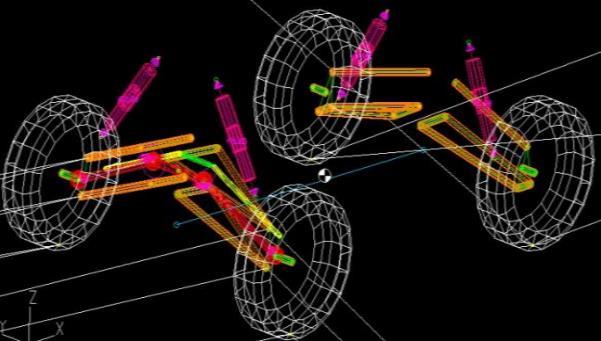
First,some initial constraints of the vehicle were fixed, which included track width, wheelbase, ground clearance, wheelradiussteeringracklength,rackposition,etc.,which helpedusfinalizethesuspensionpointsusingLotusShark software. This was done following an iterative process trying different combinations to obtain the best possible dynamic results for the vehicle; the finalized suspension geometrycanbeseeninFig[1]
The roll cage has to be designed considering the followinggoalsandrequirements.
1.BAJASAErules
2.Driversafety
3.Driverergonomics
4.Properweightbiasing
5.Properorientation&installationofsubassemblies.
6.Easeofmanufacturing
3. Design and optimization
The design process of the roll cage can mainly be divided intothreestepswhichare
1. Materialselection
2. Structuredesign
3. Analysis
Thisisaniterativeprocess whereinifwearenotsatisfied withtheresults,werepeattheprocess
3.1 Material Selection
Theselectedmaterialmustsatisfytherequirementsofthe BAJA SAE Rule book. According to the rule book, the roll cage must consist of 2 different types of members, i.e., Primaryandsecondarymembers
Forprimarymembers,therulesare
•Circularsteeltubingwithanoutsidediameterof25mm (1.0in)andawallthicknessof3mm(0.120 in.)andcarboncontentofatleast0.18%.
• A steel shape with bending stiffness and bending strength exceeding that of circular steel tubing with an outsidediameterof25mm(1.0in.)andawallthicknessof 3mm(0.120in.).Thewallthicknessmust beatleast1.57 mm (0.062 in.), and the carbon content must be at least 0.18%,regardlessofmaterial orsectionsize.Thebending stiffness and bending strength must be calculated about a neutralaxisthatgivestheminimumvalues.
ForSecondarymembers,therulesare • Secondary members must be steel tubes having a minimum wall thickness of 0.89 mm (0.035 in) and a minimum outside diameter of 25.4 mm (1.0 in) or rectangular steel tubes having a minimum wall thickness of 0.89mm (0.035 in) and a minimum outside dimension of25.4mm(1.0in).
Basedontherequirements,necessarycalculationswere performed, and a survey was conducted on the metal pipes that could be used for the vehicle. The main substitutesfoundforAISI1018(BAJArecommended)were AISI4130 and DUPLEX 2205, out of which AISI4130 was chosenforitshighweight-to-strengthratio
I=22/7*{(31.75)4–(28.45)4}/64=17723.37mm4
Bstrength=(365*13478.6/12.7)N-mm
Bstrength=387377.08N-mm=387.37N-m
Bendingstiffness=E*I=2763.12N-m²
The material used in BAJA 2022: AISI-4130 (secondary pipe)
DO=Outerdiameter=25.4mm
DI=innerdiameter=23.9mm
Thickness=1.5mm
I=π{(25.4)4-(23.9)4}/64=4413.19mm4
Bendingstiffness=E*I
Bstiffness=205*103/64{(25.4)4-(23.4)4}N-mm²
BStiffness=904.70N-m²
Here,
C=centerdistancefromtheneutralaxistoextremefiber= 12.7mm
Bendingstrength=SyI/C
BStrength=(734*5711.33)/12.7N-mm
Bstrength=255050.551N-mm=255.05N-m
AISI-4130(Primarypipe)
DO=Outerdiameter=29.21mm
DI=innerdiameter=25.91mm
Thickness=1.65mm
I=π{(29.21)4-(25.91)4}/64=13617.8992mm4
Bendingstiffness=E*I
Table -1: MaterialProperties
After checking the market availability for different sizes, the following sizes were finalized, and all the necessary calculationsarenotedbelow
Primarypipe=29.21x1.65mm
Secondarypipe=25.4x1.5mm
BendingStiffnessCalculations:
definitions,
E=modulusofelasticity(inGPa)
I= second moment of area for structural cross-section requiredtubingcross-section.
Sy=yieldstrength(AISI1018)
Diameter:1inch(25.4mm)
Wallthickness:3mm(0.12inch)
Bendingstrength=SyI/C
Bstiffness=205*103/64{(29.21)4-(25.91)4}N-mm²
BStiffness=2791.6693N-m²
Here C= center distance from the neutral axis to extreme fiber=14.905mm
Bendingstrength=SyI/C
BStrength=(734*13617.89)/14.905N-mm
Bstrength=670615.9N-mm=670.615N-m
Since the calculated values satisfy the needs, the chosen dimensionsofthe
3.2 Structural design
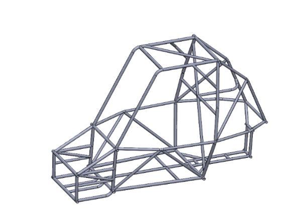
The structural design of the roll cage was carried out in SOLIDWORKS 2021 The roll cage was designed in such a way that all the safety requirements stated by SAE BAJA are met along with the needs of the driver and in a way thatitcanbemanufacturedwithease
Various designs were formulated, of which the best was selected,anditsdifferentviewscanbeseenbelow
An Ergonomics check was performed on the chosen roll cagetoensurethedriverhasasmoothride.Thecheckwas done using CATIA V5 software, where a mannequin was designedbasedonthesizeofthedriver,andthecheckwas performed by placing the driver in the various positions he would encounter sitting in the vehicle and also in the
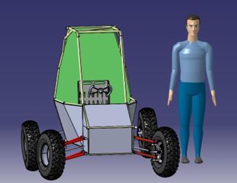


processofgettingout.
3.3 Analysis
The analysis is one of the most critical aspects of designing a roll cage as it helps us understand the structuralintegrityoftherollcage.

Static analysis has been performed on the roll cage wheretherollcagewassubjectedtothefollowingloading conditions.
Frontcrash
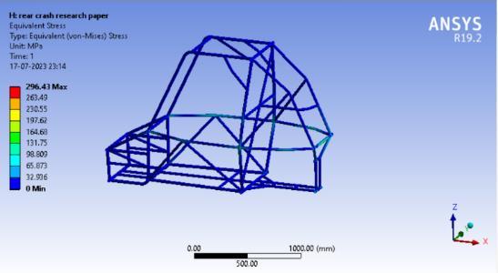
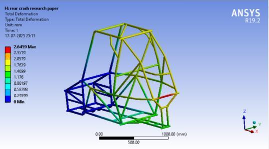
Rearcrash
Sidecrash
Torsionalstiffness
Rollover
Droptest
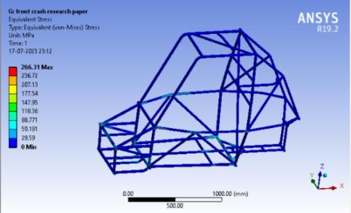
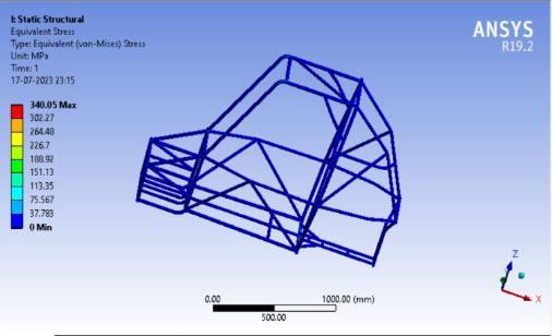
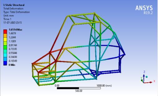
3.3.1 Front crash
For the front crash, the vehicle is subjected to a load opposite to the direction of the vehicle’s motion, and it is appliedtothememberwheretheimpactfirsthappens
Letthevelocityofourvehicleis50km/hr=13.88m/s. Suddenly,within0.3sec,itstrikesarigidwallthenthe decelerationofthevehicle.
v=u+at 0=13.88m/s+a×0.3
a=46.26m/s2
Massofbuggywithdriver=260kg
So,forceofimpactF=m×a
=260×46.26
=12027N
ThedeformationandthevonMisesstressesgeneratedcan beseeninFig7andFig8,respectively
Letthevelocityofourvehicleis50km/hr=13.88m/s. Suddenly,within0.3sec,itstrikesarigidwall,thenthe decelerationofthevehicle.
v=u+at
0=13.88m/s+a
×0.3seca=46.26m/s2
Massofbuggywithdriver=26k0g
So,forceofimpactF=m×a
=260×46.26
=12027N
12027Nforceisapplied.
ThedeformationandthevonMisesstressesgeneratedcan beseeninFig9andFig10,respectively.
Letthevelocityofourvehicleis50km/hr=13.88m/s. Suddenly,within0.3sec,itstrikesarigidwall,thenthe decelerationofthevehicle.
v=u+at0=13.88m/s+a
×0.3seca=46.26m/s2
Massofbuggywithdriver=26k0g
So,forceofimpactF=m×a
=260×46.26


=12027N
12027Nforceisapplied.
ThedeformationandthevonMisesstressesgeneratedcan beseeninFig11andFig12,respectively.
The weight distribution of our vehicle is 53:47(Rear: Front)
So,
Forcetransferfromreartofrontaftertheapplicationof brakeatbumpis32%ofthetotalweight.
So,theweightonthefrontaxle
F=0.53×260×9.81
=1351.818N
Acoupleisgenerated,whichtriestotwisttheroll Cage,so1351.818Nforceisappliedonfour mountingpointsofwishbone,i.e.

337.95Noneachmountingpoint.
Acoupleiscreatedbyfourforcesinanupward direction&fourindownwarddirection.
Letussupposetheforcesofcoupleareactingon themeanofthenose
Lengthi.e.(300+300)/2=300mm
Tan��=Deflection/(meanofnoselength/2)
Tan��=0.020
��=1.145deg
Now,fortorque
OurFronttrackwidthis1.35m
So,appliedtorqueonthefrontsectionofourroll cageisT=F×1/2(trackwidth)

=1351.818N×0.675m
=911.477N-m
So,theTorsionalstiffnessofourroll cageisK=T/��
=911.477/0.1451N-m/deg
=796.60N-m/deg
ThedeformationandthevonMisesstressesgeneratedcan beseeninFig12andFig13,respectively.
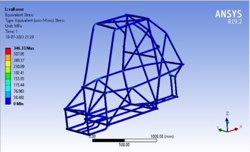
Incaseofarollover,theeffectontherollcageisduetothe self-weightof thevehicle
i.e.
1gforceso,F=260×2×9.81=2550.6N
ThedeformationandthevonMisesstressesgeneratedcan beseeninFig13andFig14,respectively.
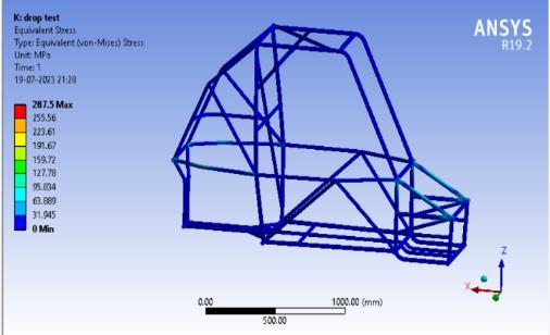
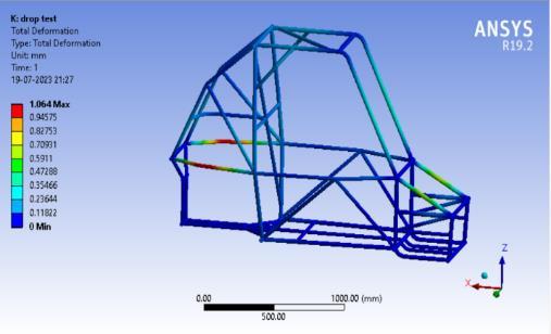
3.3.6 Drop test
Letusassumethatourvehicleisdroppedfrom1m heightandletthetimeofimpactis0.3sec
V=√2gh =√(2x9.81x1) =4.42m/s
Dampercompression=d=0.8
Energy transfer by roll cage = w = 1/2mv2 = F.d Vertical force=
f=w/d=(1/2mv2
)/d=3174.665N
ThedeformationandthevonMisesstressesgeneratedcan beseeninFig15andFig16,respectively.
Factorofsafety=Yieldstrength/Maximumstress
Where maximum stress is the stress observed during the analysis
After performing the analysis, the results are tabulated and the Factor Of Safety (FOS) is calculated using the formula
4. CONCLUSIONS
The design of the roll cage was successfully completed, meeting all the set goals and safety requirements. Achieving thisinvolved a number ofiterations in order to get the best possible results. Various calculations were performed to optimize the design and involved using various software like ANSYS, SOLIDWORKS 2021, CATIA V5,andLOTUSSHARK.
5. REFERENCES:
Bhandari, V. B. Design of machineelements. Tata McGraw-HillEducation,2010.
R.K. Rajput, A Textbook of Automobile Engineering.LaxmiPublications(P)LTD,2007
T. D. Gillespie, Fundamentals of Vehicle Dynamics, Warrendale, PA, SAE Publication, 1992.
HeinzHeisler,AdvanceVehicleDynamics.
Dr.R.K.Bansal, A Textbook Of Strength Of Materials,Thirdedition:1996