Efficient Design for Multi-story Building Using Pre-Fabricated Steel Structure by Integrating It with BIM Application
Samrudh1 , Shruti G2 , Sharat Chouka31 Master’s Student, Department of Civil Engineering
Poojya Doddappa Appa College of Engineering, Kalaburagi, Karnataka, India. -585102
2 Asst. Professor, Department of Civil Engineering

Poojya Doddappa Appa College of Engineering, Kalaburagi, Karnataka, India. -585102
3 Asst. Professor, Department of Civil Engineering
Poojya Doddappa Appa College of Engineering, Kalaburagi, Karnataka, India. -585102 ***
Abstract - Pre-fabricated steel structures used in a construction of buildings to overcome the problems like natural hazards, wastage, safety and to improve the productivity through saving cost and time. In this adequate structural design and effective manufacturing are both integral process for the efficient steel structure. The steel structure design significantly reduces the overall cost, increase the safety, sustainability, productivity and reduces the construction time. The use of Building Information Modelling (BIM) in this structure increases the product quality and this also provide the accurate quantity to take off and improve the scheduling and provide cost saving techniques. BIM helps to represents the different dimensions like 2D, 3D, 4D & 5D models to stimulate the planning, design, construction, and operation. It helps AEC (Architects, Engineers & Constructors) to visualize what is to be built in stimulated time and identify the operational problems. So, the project report extends us to know the designing of the pre-fabricated steel structure using Indian Standard Code inthe STAAD.pro software for structural analysis, for 2-Dimensional plan Autodesk’s AutoCAD software is used and to represent the drawing in 3-dimensional Autodesk’s Revit software is used and later for the 4 Dimensional i.e., scheduling of the works is done in Autodesk’s Navisworks in this time management is done andclashes were also detected. This BIM applicationmade the work easy during the construction and avoid the delay and proper management is done due to which there is no conflict of interest betweenthe Client & Contractor.
Key Words: BIM, Pre-fabricated steel, Navisworks, AEC, Scheduling, Clash Detection.
1.INTRODUCTION
1.1 Prefabricated Steel Structure
A Prefabricated steel structure is basically a structure thatismadeupofsteel.Thesestructuresareengineeredat the factory and get assembled at the site. In prefabricated steel structure construction framing will be fabricated completelyatthefactoryandtransportedtothesiteforthe assembling.
Multi-storiedsteelstructureistypicallyfabricatedwith the structural frames which are fabricated out of steel. It consistsofcolumnsandbeamswhicharecustomizedwith respect to the building and most of the nodes are rigidly connected.Theframestructureisthemostcommonamong the steel structured multi-storied building. The frame structureisthetypicallyverticalloadbearingstructure.
1.2 Building Information Modelling
Buildinginformationmodelingisthedigitalprestation ofphysicalandfunctionalcharacteristicsofthebuilding.BIM integratesthestructuredandmulti-disciplinarydataforthe assistance throughout the lifecycle i.e., from planning, designing to construction and operations (AEC-Architect, Engineering&Constructionindustry).
TheconceptBIM wasfirststartedinlate1970s.The softwaretoolsemergedduringlate1970sandearly1980s forthemodelingbuildingswereGLIDE,RUCAPS,SONATA, ArchiCAD,REFLEX&GABLE4DSeries.ThetermBIM was first used in the papers in 1985 by Simon Ruffle. BIM is officially recognized by international standard in 2013 by givinganISOcodeISO-16739andlaterin2019depending ontheUKpapersISOpublishedseriesasISO-19650.
In India IBIMA (India Building Information Modeling Association)isanationallevelsocietywhichrepresentsthe entire BIM community. In India due to population growth and economic growth there is expand in the construction market.Indian government officialsgavea statementthat BIM could save around 20% of the construction time and giveascopeforthewiderinfrastructuredevelopment.
Itwasobservedthatduetoincreaseinthepopulation anddemandintheinfrastructuredevelopmenttodaythere isabigfaultlineduetowhichAEC(Architect,Engineering and Construction) community are unable to full fill the demandontime.Thefaultlinesmightbeduetothebudget constraintsoralsomightbebecauseoftheavailabilityofthe areaetc.So,weneedtodesignthestructureinmoreefficient way like budget friendly, good utilisation of space and reducingtheconstructiontimewithgooddurabilityofthe structure.
2. METHODOLOGY
This project provides the information and demonstration of the designing of the five-story steel building i.e., prefabricated steel structure for the multipurposeworkspaceandunderstandinghowBIM(Building InformationModelling)canbeutilisedinthebuildingdesign tomakethebuildingmoreefficient.Theplotareaconsidered fortheconstructionofthebuildingis100x60metersi.e., 6000sqmtofplotarea.Themethodologyconsideredinthis projectisfirstlywedesignthebuildingandintegrateitwith BIM.Thebasicstagesinvolvedinthisare:
First stage the building planning is done through AutoCADsoftwareandthestructuraldesignisalso done in this level only, through Staad Pro V8i software, sections are designed and analysed throughwhichwegetthestructuralstabilityofthe building.

Second stage after knowing the plan, section, and structuraldesignofthebuildingthe3Dmodelofthe buildingiscreatedinRevitarchitecturesoftwareand for the structural member the Revit structure softwarecanbeused.
Nowinthirdstagethe4Dmodelingofthebuildingis done i.e., time management through the software calledAutodeskNavisworks.
ThedesigncodesaretobeusedaspertheIndianstandards:
IS875–CodeofPracticeforDesignLoads
IS 1893 – Criteria for Earthquake Resistant Design of Structures

IS800–GeneralConstructioninSteel
BuildingBye-Laws2017–GovernmentofKarnataka
3.
11. Loads IndianStandards
12. Soiⅼ type HardSoil
13. SeismicZone ZoneII
Table 1 General Properties
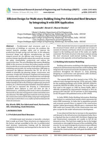
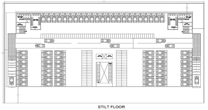
3.2AutoCAD2-DimensionalDrawings
4. STRUCTURAL DESIGN AND ANALYSIS IN STAAD.PRO
4.1 Introduction to Staad.Pro
The structural analysis programme STAAD.PRO is renowned for its analysis, variety of applications, compatibility,andtime-savingfeatures.Inordertoperform 3Dstructuralanalysisanddesignforbothsteelandconcrete structures,structuralengineersuseSTAAD.
Ananalyticalmodelforstructuralanalysiscanbebuilt from a physical model created in the structural design programme.Toensurethatthestructuraldesigncomplies with local laws, STAAD incorporates a number of design codestandards.
4.2 Designing and Analysis Procedure in Staad.Pro
1. OpenSTAAD.ProV8iSoftwaretheselectthespaceoption theselectthelengthsppecificationmeterandkilonewton thenselectnextandfinishoption
2. JobInformationiscreatedforthespecified
3. Modellingisdonebyaddingandjoingnodeswithrespect tothedistanceandshapeofthebuildinglaterjoinedit with beamoption from the top toolbox and layered to different floors and keeping in mind of providing the expansionjoint.
4. Nowaddplatesectiontoeachfloorastheslab,forthatgo selectthe4nodeplateoptionfromthetoptoolboxlater selecttheplatecursorthendrawtheplateforallthefloor.
5. Now to assign the section data base for the beam and columngotogeneralandselectthepropertytheselect thesectiondatabasethereselectthesteelcolumnandgo toIndianselectthewsectionandspecifythebeamand columnspecificationsandaddit.

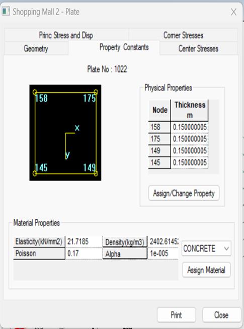
6. Now to select the thickness and add slab thickness od 150mmi.e0.15thenclickonadd
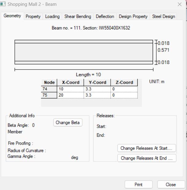
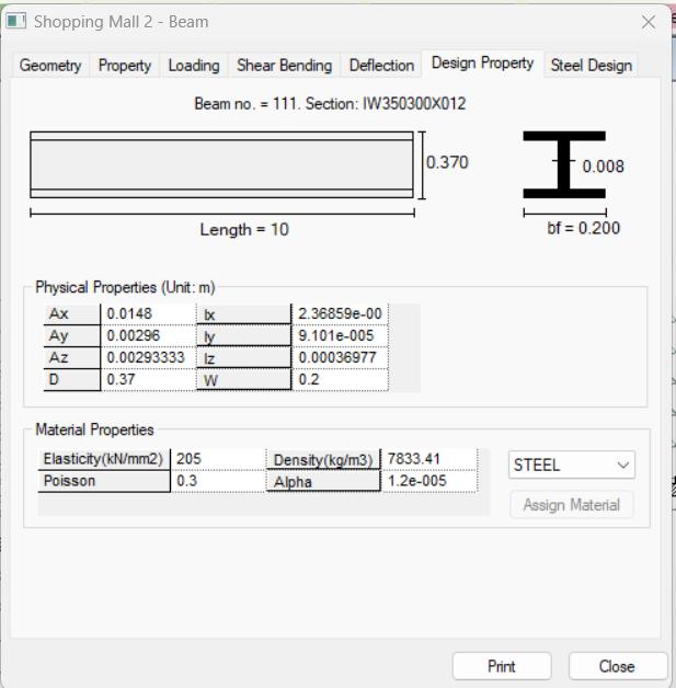
7. Now associate all the beams, columns and slab to the membersandrendertoseethesteelbuilding. Forthefollowingsteelbuildingthespecificationisgiven:
Beams=IW550400x1632(Steel)
Columns=IW550400x2040(Steel)
Plate=150mm(Concrete)
8. Nowtogiveasupportgothegeneralandselectsupport andselectcreatesupportselectthefixedsupportselect oktheaddthesupporttothestructure.
9. NowtoaddtheLoadsgotogeneralandselecttheLoads andDefinitionselecttheloadcasedetailsaddDeadLoad, LiveLoad,WallLoad&SelectAutoloadCombinationfor theotherloads.
DeadLoad=Selfweight-1KN/m2
LiveLoad=5KN/m2
WallLoad=5.37KN/m2
LoadCombination
10. Now to add materials go to general and select the materialsandassignedmaterialswillbeobservedifnot assignit.
11. NowtodotheanalysisgotoAnalysis/Printoptionclick onapplyandgotopostprocessingherewecanobserve thedisplacement,reactionsofnodesandforces,stresses ofbeamandcontourofplates.
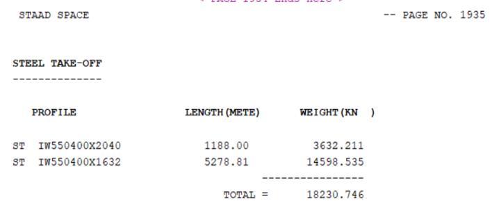
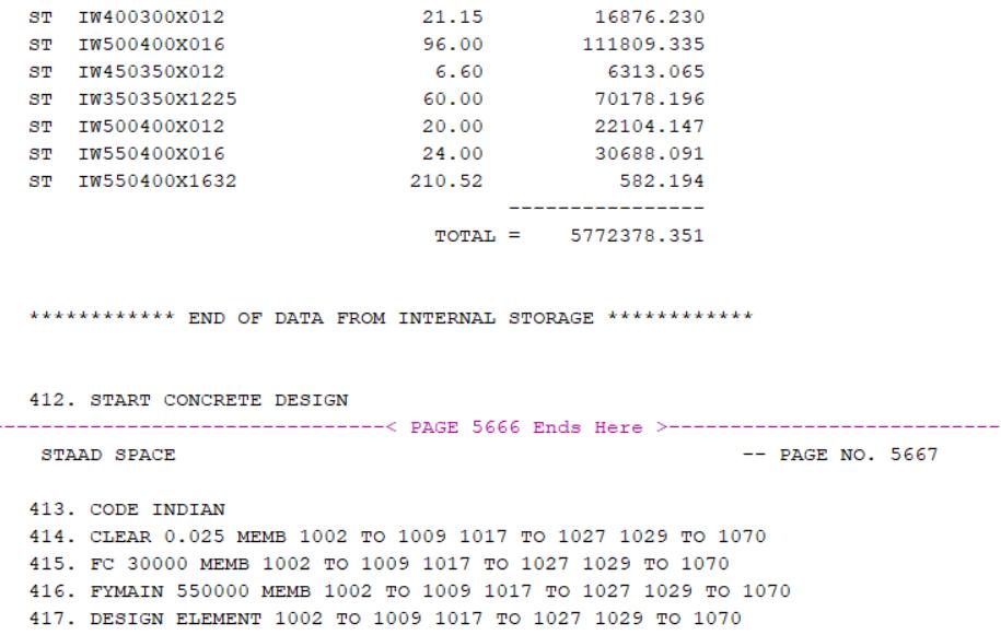
12. Nowneedtodesignthesteelandconcretemembertodo thatgotomodellingandselectthedesignandchoosethe steelmember,changethecodetotheIndianstandardsi.e IS8002007LSDandselecttheparametersI.eTrack& Yield Strength of 550000kn/m2 and define the parameterstothesteelmembersandgivethecommand of check code, member take off, select & take off. Now assignthesteelmembersi.ebeamsandcolumnsforall theparameters.
13. Now choose concrte design and select the IS 456 and select the parameters of Clear cover, Compressive strength & Yield strength and define parameters of 0.025m,30000kn/m2&550000kn/m2repectivielynow go to command and select design elemets and take off afterassigntheslabs.
14. NowselectAnalysis/Printoptionandclickonapplyand laterrunanalysisandgotopostprocessingandcheck fortheoutputfile
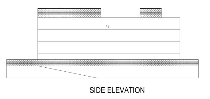
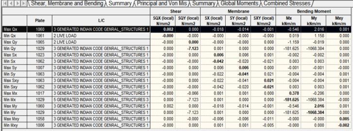
4.3 Output of the design and analysis in Staad.pro


5.1 Introduction to Autodesk Revit
For structural engineers, mechanical, electrical, and plumbing (MEP) engineers, designers, and contractors, Autodesk Revit is a building information modelling programme.CharlesRiverprogramme,a1997startupthat changeditsnametoRevitTechnologyCorporationandwas lateracquiredbyAutodeskin2002,wasthecompanythat created the initial programme. The programme enables users to create a building and all its parts in 3D, add 2D draftingelementstothemodel,andretrievebuildingdata fromthebuildingmodel'sdatabase.
5.2 Designing Procedure in Autodesk Revit


StarttheAutodesk Revitapplicationandselectthe templet insert the Autodesk AutoCAD drawing file throughgoingtotheinsetoptioninthetoolbarand insertthefile.
CreatethedifferentLevelsbygoingtoelevationand therewillgettheinsertleveloptioninthetoolbar andplaceitatthedifferentlevelsofbuilding
Drawthewallsalongtheplanandgivetheproperties tothewallfor6inchand9-inchwallandgotothe toolbarandplacethedoorsandwindows
Nowgotothecirculationinthetoolbaranddraw thestaircasepathbyselectingthetypeandboundary andpathway.
Nowselecttheflooringfromtoolbaranddrawthe boundary of flooring and enter which kind of flooringbychangingtheproperties.
Drawthesamethingstoalltherestofthefloorsand mentionthethingsandlaterselecttheceilingfrom thetoolbardrawtheboundaryofceilingandapply theproperty.
Now place the lighting, furniture, and plumbing workstoallthefloorsbygoingtocomponentsand loadinglibrarythenplacingitinrequiredplaces.
Nowgototheviewplacetopographyandgivethe angleforthecameratovisualrepresentationofthe drawing.
Forthewalkthroughoptiongototheviewandselect the 3D option from the menu bar and draw the patternofthewalkthrough andexitlaterrenderit andexport.
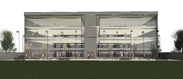
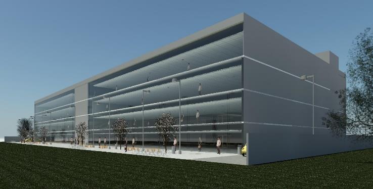
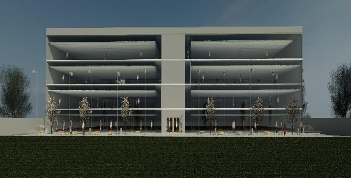
5.3 Output of the Design in Revit

6. 4-DIMENSIONAL DESIGN IN AUTODESK NAVISWORKS
6.1 Introduction to Autodesk Navisworks
Inthisusercanevaluate3DdesignsusingNavisworks. Users of Navisworks can open and combine 3D models, navigatethroughtheminreal-time,andreviewthemodel using a variety of tools including comments, redlining, viewpoints, and measurements. Navisworks is primarily usedinthearchitecture,engineering,andconstruction(AEC) industriesasacomplementto3Ddesignpackages(suchas Autodesk Revit, AutoCAD, and MicroStation). Interference detection,4Dtimesimulation,photorealisticrendering,and PDF-likepublicationaresomeoftheplug-insthatimprove theprogram.

6.2 Designing Procedure in Autodesk Navisworks
SavethefileinNWCfileinthe3Dmodellingsoftwareand openitthenitcreatesthecacheofNavisworkslatersave thefileinNWFsothattocarryonthefurtherusage.
TheGeneraluserinterfacescreenopenstocarryoutthe workof4Dmodelingandthe3DModelwillappear
Now for the 4D Modelling i.e., scheduling and time managementgototheTimeLineroptioninthetoolbar ofthescreenandclickonittheinterfacepopsonscreen
Nowscheduletheitemsfromtheselectiontreeandselect thedateandtimeoftheworkwhichstartandend.
Nowtochecktheclashdetectivitygotothetoolbarselect theclashdetectionoptionandlaterthesubscreenpops upandselectthestructureandrunthetest.Itwilldetect tthenumberofworkswhichmayoverlapandshowsthe tolerancelevelandstatusofdifficultyintheprogressof work.
Nowgotothesimulateandcreatetheanimationsand sectionslaterexportittoBIM360andshare
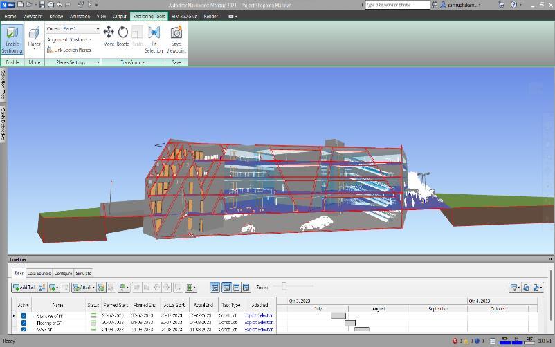
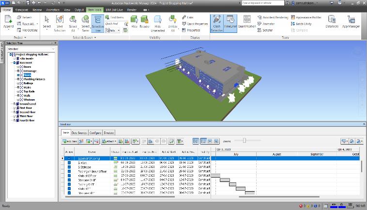
6.3 Output of the Design in Navisworks
7. OBSERVATION AND DISCUSSIONS
7.1 Importance of BIM in AEC Industry


InthisitwasnotedthathowBIMhelpedfordigitalized documentationatthepre-constructionstage.Also,withthis itwasnotedthatBIMreducedtheconstructiontime,cost, andcompressivechecks.Itwasnotedthattheerrorduring the construction phase has drastically reduced because of theprevisualisationofthemodel,simulationofthemodel and detectivity of the clashes. BIM also keeps the information of all the phases of the project, status of the workandcontinuityoffwork.Alltheteammembersofthat projectcanaccesstoworkirrespectiveofplacewherethey are,duetowhichthemanagementandcoordinationwillbe greatduringtheconstructionphasewhichalsoreducesthe
wastage.Inthisprojectthe2D,3D,4Dmodellingisdoneand structuralanalysisisalsodonetospecifythestabilityand visualizationofthebuilding.


7.2 Modelling and Design Properties of the Building.
In this phase of project, the kind of the building was decided to design and got to conclusion that the prefabricatedsteelstructurecouldbeusedforthebuilding, it was noted from the literature survey the usage of prefabricatedsteelinthebuildingismoreefficientascompared toconventionalconcreteforbeamsandcolumns.Byusing theprefabricatedsteelstructure,theutilityspacewillalso increaseandtheconstructioncostandconstructiontimeof thebuildingwillbereduced.Thebuildingisforcommercial usage i.e., Shopping Mall complex so the norms for the buildingdesignisdonewithrespecttothebuildingbylaws ofKarnatakaUrbanDevelopmentAuthority.Thebuildingis of Stilt + 4 Floors so while designing this building it was consideredofthespecificationofcommercialbuildingand designed accordingly for example the passage should be givenwiththewidthof2meters,provisionsofstaircaseand elevatorsrespectivelyandprovisionsofthewashroomsand ventilations,manymoresafetyprecautions.
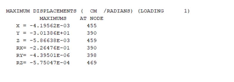
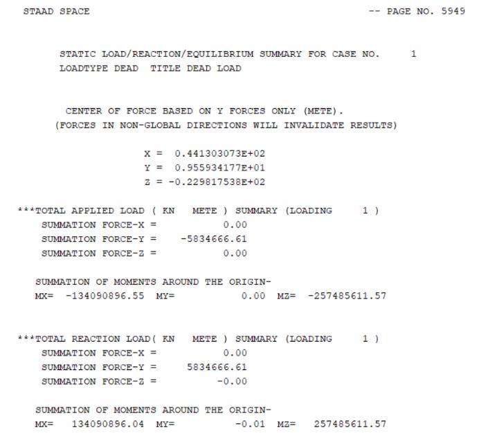
7.3 Analyzing the Structural Properties of the Building.
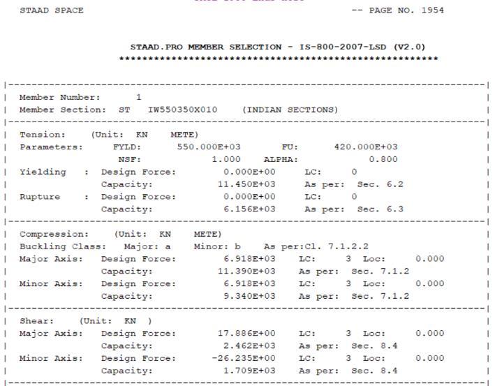
Inthisphaseoftheprojectstructureofthebuildingis analysed, it was noted that the structural properties are designed with respect to the Indian standards and critical valuesaretakenintoconsiderationforbeamsandcolumnsof steeltodesign.Thestructuralanalysisanddesignaredonein Staad.prosoftwarewhichmadeatounderstandtheRelative displacement, Forces acting on Beams and Plates, Stresses acting on Beams and Plates, Maximum absolute value of Loading, General Properties, Design Properties, Shear Bending, Steel Design, Moment Connections and Shear Connectionsmanymore.Inthissoftwarethedesignisdonein suchawaythestructuralmembershouldbemoreefficient forexample,bytakingtheMember-1detailsintheanalysis part the given property was at the higher node and steel valuewasalsohigherbutafterperformingDesignanalysis thesteelvalueofthesamememberisdesignedaccordingthe loadcombinationandthequantitiesarecalculatedtheresults pagearelike,


7.3 Designing the 3-Dimensional Model.
Inthisphaseoftheproject,itwasnotedthatthefloor plan of the building was designed in the 3-Dimensional model withthehelpofsoftwareAutodeskRevittogetthe broaderperspectiveofthedesignandunderstandthereallifeexperience,inthisphaseallthecomponentswereplaced inthebuildinganddesignedwithglazingaccordingtothe requirementlikeFlooring,Ceiling,Lighting,WallCladding, Stairs, Elevators, and many more after designing the 3 DimensionalModel,thebuildingwasviewedfromdifferent anglesandwalkthroughwasdonesothereallifeexperience can be done and later the views are rendered because to watch the building in different lighting condition of the eyesight.Throughthisphaseofmodellingthesectioncanbe mentionedclearlyandstagesarealsomentionedwiththe components this will be useful for the further designing process.
7.5 Designing the 4-Dimensional Model.
Inthisphaseoftheproject,itwasnotedthescheduling of the work is done with respect to the duration of the constructionandvisualisedwithrespecttothetime.Thiscan be done through 4-Dimensional Modelling i.e., through softwareAutodeskNavisworksManagethissoftwareisused forthe4-Dimensionaland5-DimensionalModelling,thefile


is imported from the Autodesk Revit where all the components were mentioned with their stages so in this software by scheduling the time to that component it will calculatetheworkprocedureandtime.Thespecialabilityof thissoftwareistodetectedtheclashessothatwecangetthe clear idea at pre construction phase only about the overlappingofworksothatwecanreassigntheworklater theclashcanbeavoidedandduetotimeschedulingisdoneby simulatingthestepswegettoknowthepaceoftheworkit can be used in all the three phases in pre-construction to checktheclashesandprovidethetimedetails,inconstruction tomatchoverthethingsandpostconstructiontocalculate andanalysethethings.
8. CONCLUSION
This project gives the systematic approach for the constructionofmultistoreybuildingwithprefabricatedsteel structure which is highly efficient with respect to constructionandwithrespecttothespaceutilisation.Inthis model of presentation, the Key plan is done in AutoCAD software and it is visualised in 3-Dimensional through Autodesk Revit later analysed the structural aspects in BentlySTAAD.prosoftwareandfortimemanagementthatis 4-Dimensional modelling is done in Autodesk Navisworks Manage. During the structural analysis all the Indian Standard Codes are used for the Steel Design IS 800, for Loading IS 875, for RCC IS 456 and taken to the consideration that the steel columns and beams are in W sectionwhicharemorestableandproductiveascompared toanyotherandlaterthejointsareconnectedwithnutand bolts. From the analysis it was known that the maximum deflections,displacements,andforcesareactingonthebody through generated loads and all the critical loads are examinedandthemaximumspaniscalculatedandprovided sothatmoreutilityofspacecanbedone.Thewalkthroughis doneforthe3-Dimensional Model intheRevitso thatthe clear idea would come and later it is rendered so that the realistic approach can be shown. In the 4-Dimensional Modellingtheschedulingisdonewithrespecttothework andthethingsaresimulatedsotogetinformationabouthow itworks.Throughwhichtheconstructiontimeisreducedby 40% and construction cost is reduced by 20-30% when comparedtotheconventionalmethodofconstructionand wastageisreducedtojustlessthan2%andoverlappingof theworksisalmostequaltoNil.DuetothisBIMapplication thecloseapproachtotherealitycanbevisualisedandcan reduce the mistake and disputes between the contractor engineerandclientduringtheconstructions.
Theuseofprefabricatedsteelstructureisnotactively usedotherthanTier-IcityinIndiabecauseoftheavailability andtransportation,toresolvetheconditionisfuturescope ofdiscussionandimplementationofBIMtechniquesinthis projectopenthepathforthefurtherresearchforotherthen prefabricatedsteelstructurelikeforconventionalconcrete structureorpre-stressedstructureandmanymoreforthe
Construction Scheduling, Construction Management, ConstructionSafetyandVisualizing.
DECLARATIONS
Conflict Of Interests: The authors have no competing interests to declare that are relevant financial or nonfinancialintereststodiscloseornoconflictofinterest.
Funding:Nofundingwasreceivedforconductingthisstudy
Allsigningauthorsparticipatedinwritingofthearticle.All authorsapprovedthepublishingversionofmanuscript
REFERENCE
[1] Mooyoung Yoo, Jaejun Kim, Changsik Choi, “Effects of BIM-BasedConstructionofPrefabricatedSteelFramework from the Perspective of SMEs,” Applied Sciences, 26 April 2019,9,1732.
[2]ShengxinChen,JieWu,JialinShi,“ABIMPlatformforthe Manufacture of Prefabricated Steel Structure,” Applied Sciences,13November2020,10,8038
[3]ZhanZhenguang,“ApplicationofBIMTechnologyinthe Construction Phase of Steel Structure Engineering,” IOP Conference Series: Earth and Environmental Science, October2021,783,012118
[4] Rafaela Bortolini, Carlos Torres Formoso, Daniela D. Viana,“Sitelogisticsplanningandcontrol for engineer-toorder prefabricated building systems using BIM 4D modeling,”Elsevier,29November2018,98(2019)248-264
[5]Yin-GangWang,Xiong-JunHe,JiaHe,ChengFan,“Virtual Trial assembly of steel structure based on BIM platform”, Elsevier,31May2022,141(2022)104395
[6] Shi An, Pablo Martinez, Mohamed Al Hussein, Rafiq Ahmad,“Automatedverificationof3Dmanufacturabilityfor steelframeassemblies”,Elsevier,28May2020,118(2020) 103287
[7]Ling-KunChen,Rui-PengYuan,Xing-JunJi,Xing-YuLu, JiangXiao,Jun-BoTao,XinKang,XinLi,Zhen-HuaHe,Shu Quan,Li-ZhongJiang,“Modularcompositebuildinginurgent emergencyengineeringprojects:Acasestudyofaccelerated design and construction of Wuhan Thunder God Mountain/Leishenshan hospital to Covid 19 pandemic” , Elsevier,18December2020,124(2021)103555
[8] Mohammad Delavar, John K Dickinson, Girma T Bitsuamlak “Discussion on BIM Implementation in PreEngineered Building Industry”,Researchgate , 4 June2016, GEN-178
[9] Jose Ignacio Avendano, Sisi Zlatanova, Pedro Perez, AlbertoDomingoandChristianCorrea,“IntegrationofBIM
in Steel Building Projects (BIM-DFE): A Delphi Survey”, MDPI,13September2022,12,1439
[10] Deepa Patil, “Building Information Modelling ApplicationinConstructionIndustry”,InternationalJournal ofScienceandResearch(IJSR),5May2020,SR20525213518
[11]SomnathDKhochare,AshishPWaghmare,“3D,4Dand 5DBuildingInformationModellingforCommercialBuilding Projects”,InternationalResearchJournalofEngineeringand Technology,5January2018,2395-0056
[12]JessieYa-TingHo,SatishMohan,“BuildingInformation ModelingApplicationsinConstructionManagement–Acase study for modeling information and outcomes”, American JournalofEngineeringResearch,28March2021,2320-0847
[13]IS:800(2007),―IndianStandardCodeofPracticefor General ConstructionInSteel Bureauof IndianStandards, NewDelhi.
[14]IS:875(Part1),―IndianStandardCodeofPracticefor design loads for building and structures, Dead Loads‖ BureauofIndianStandards,NewDelhi.
[15]IS:875(Part2),―IndianStandardCodeofPracticefor designloadsforbuildingandstructures,LiveLoads‖Bureau ofIndianStandards,NewDelhi.
[16] IS 456:2000, ―Indian Standard Plain and Reinforced Concrete-CodeofPractice‖,BureauofIndianStandards,New Delhi,2000.
[17] Building Bye-Laws for Urban Areas, Urban Development,GovernmentofKarnataka,2017.
[18] Dana K Smith, Michael Tardif, “Building Information Modeling–AStrategicImplementationGuide”,JohnWiley& Sons,2009
[19] S K Duggal, “Design of Steel Structures”, 3rd Edition, McGrawHill,2017