VEHICLES PARKING BY USING HYDRAULIC SYSTEM
Prashant S. Kottalagi1 , Mahesh P. Patil2 , Saloni I. Jamadar3123Student, Department of Mechanical Engineering, Kolhapur Institute of Technology’s College of Engineering Kolhapur. ***
Abstract - The aim of this project is to produce hydraulic system for parking the vehicles.Generally,inpublic mallsmulti level parking is present, for travel the vehiclefromfirstfloorto second floor is carried out with the help of ramp. The construction of ramp requires cost and huge space To overcome this disadvantage we have designed hydraulic system. By using this hydraulic parkingsystemwecantransfer the vehicle from first floor to second floor without usingramp. We proposed simple hydraulic circuit by using Automation Studio software.
Key Words: pump, oil reservoir, direction control valve, counter balance valve, actuator, hoses etc.
1. INTRODUCTION
Themajorprobleminanyoftheparkingsystemaretraffic jamsandlackofparkingspaces,thisproblemissolvedby automaticcarparkingusinghydraulicsystem.Thishydraulic carparkingsystemplaysacrucialroletoutilizethespace whichisoccupiedbyrampsinmultilevelcarparkingsystem.
The multilevel car parking has to deal with the traffic congestion which leads to loss of time, the hydraulic car parking system prevents the traffic congestion as the parking is automated and also prevents change caused during manual parking in multilevel car parking The hydrauliccarparkingisdurableandsecurewhichconsistof piston cylinder arrangement, counterbalance valve, directionalcontrolvalve,pressurereliefvalve,pump,motor, filterandreservoir.
Duringparkingoperationcarisraisedandloweredsmoothly within certain time which benefits the user as this avoids extra time required to take out the car from first floor to groundfloorthroughrampsinmanualcase.Thehydraulic carparkingcanbeoperatedbyoneortwooperatorswhich reduce the labour cost also the hydraulic parking system helpsinticketingwithlesstimeandlessmanpowerwhich resultsinlowcostofmanagementandfasterprocessing.
2. LITRETURE REVIEW

TheresearchdonehydrauliccarparkingbyWhorsaysthat, there are different parking systems, like multilevel car parkingsystemutilizesanelectricmotororhydraulicpower to lift and transport comes from the entry level to vacant spacesonupperlevels.

TheresearchdonebyRahulKolekar,S.S.Gawadesaysthat metropolitan cities strongly need an advanced parking system, so they have developed a lift for parking which is operatedbyhydraulicsystem.Thiswillprovideconsiderable negotiableparkingpricesandselectstheoptimalcarparkfor driver.
According to research Shannon Saunders on hydraulic parking system to gave the opacity which occupied by the hydraulicpoursparkandactuatorssystemwhichwillhelp utilizethetightspacesaccusedbyminimaparking.
3. CONSTRUCTION
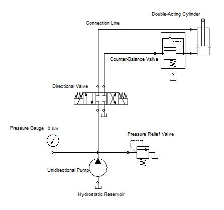
The hydraulic parking system consists of a hydraulic Actuator which has a piston, connecting rod and double actingcylinderthecounterbalancevalvewhichisconnected at lower end of cylinder. The Directional control valve is used for changing the direction of fluid flow into the actuator, we have used pressure relief valve for safety purposewithPressuregaugeforpressuremeasurement.
The electric motor is connected to the hydraulic pump to providemotionandinlinefilterisconnectedtoremovethe Dust and solid particles from fluid. For Storing fluid the reservoirisinstalledwhich storesthehydraulicfluid.The cariskeptonasquareplatewhichisoperatedbyhydraulic Actuator.
4. FUNCTIONS OF COMPONENT
1) Reservoir:-
Tostoresufficientamountofhydraulicoilrequiredforthe systemandcoolthehotreturnoil.
2) Filter :-
Toremovethedirtandparticlespresentintheoil.
3) Pump:-
Thefunctionofrotarypumpistopumphydraulicoilto thehydrauliccircuitbyincreasingthepressureofoil.
4) Pressure control valve:-
Thisvalveisheartoftheeveryhydraulicsystem.Itisused forcontrolpressureinsidethesystemforsafetypurpose. Thisvalveisconnectedattheoutletofpump.
5) Pressure gauge :-
To indicate the pressure generated inside the system. Pressuressettingaremadebylookingtopressuregauge.
6) Direction control valve:-
Tocontroltheforwardandreversemotionofactuatorby changingtheleverdirectionorpushbuttonposition.
7) Counter-balance valve:-
Counterbalance valves are used in hydraulic systems working with an overriding (run-away) or suspended load. They are designed tocreate backpressure at the returnlineoftheactuatortopreventlosingcontrolover theload
8) Actuator:-
Theactuatorinhydrauliccontrolsystemistoconvertthe hydraulicenergyproducedbythepumpintousefulwork.
9) Hoses:-
Hoses are used to carry fluids through air or fluid environments,theyaretypicallyusedwithclamps,spigots andnozzlestocontrolthefluidflow.
5. WORKING
ThehydraulicsystemworksontheprincipleofPascallaw. Statement: According to Pascal law, “the external static pressure applied on the confined liquid is distributed or transmittedevenlythroughouttheliquidinalldirection”

Thepurposeddesignismadeforraisingandloweringthe car.HerewehaveusedhydraulicpowerpackandDCVfor theoperationwehaveprovidedthereservoirwhichcontains sufficientamountsofhydraulicfluid.
Thehydraulicpackconsistsofapressurereliefvalveanda hydraulicpump,electricmotor,filterandreservoir.When liftingthecar,hydraulicpumptransferorsupplytheoiltoby direction control valve, which then transferred to the Actuator.TheActuatorconsistsofpistonandcylinder.Due totheforceoffluidthepistonmovesandthereforethecar liftedsmoothly,wehaveprovidedacounterbalancevalveso thatduringloweringthecar,themovementwillbesmooth; otherwisethecarwillcomedownathighspeedwhichwill damagetheentiresystem.Wehavealsoprovidedpressure reliefvalve,sowhenthesystempressuregoesbeyondthe limit,thepressurereliefvalvewillreleasethepressurized fluid back to the reservoir until the pressure reaches to normal. The motion of raising and lowering of the car is withinshorttimewhichsavesthetime.
The prime components used in the system are hydraulic actuator, directional control valve, counterbalance valve, pressurereliefvalve,motor,pump,pressuregauge,hoseand reservoir. The following are the formulas for getting the dimensionfortheconstrainedconditionofdesign.
1) For hydraulic actuator :
Frommanufacturer’scataloguerodandborediameterareto beselected.
P=F/A
Where,
P=pressure
F=force
A=area
Forflowrate: Q=A×V
Where, Q=discharge
V=velocity
2) For pump:
Pump is selected from manufacturer’s catalogue based on flowrateandpressureofoil.
3) For pressure relief valve (PRV) and direction control valve (DCV):
PRV and DCV are selected from manufacturer’s catalogue basedonworkingpressure.
4) For selection of tubing :
Inner and outer diameter of tubing is selected from manufacturer’scataloguebasedonvelocityandflowrateof oil.
5) For counterbalance valve :
Counterbalance valve is selected from manufacture’s cataloguebasedonmaximumpressureinthesystem.
6) Reservoir capacity:
Reservoircapacity=3or4×Q
7) Selection of motor :
Motor is selected as per the requirement of speed for the hydraulicsystem.
8. CONCLUSIONS
For parking the vehicles in multilevel parking system requiresramp,duetothisconstructioncostoframpishigh andalsorampoccupiesmorespaceoffloor.Weknowthat costsoflandsincitiesareveryhigh.So,byusinghydraulic systemforparkingthecar,wecaneliminatetheramp.The costrequiredforthehydraulicsystemislessascompareto costofconstructionoframp;hencewecanreducethecost andcanutilizethespaceoccupiedbyramp.
9. REFERENCES
E.JohnFinnemore,JosephFranzini"FluidMechanics withEngineeringApplications",McGraw-Hill,2002
Cassidy,JohnJ.,Chaudhry,M.Hanif,andRoberson,John A."HydraulicEngineering",JohnWiley&Sons,1998
Kirby, B.J. (2010).Micro- and Nanoscale Fluid Mechanics:TransportinMicrofluidicDevices:Chapter3: Hydraulic Circuit Analysis. Cambridge University Press.ISBN978-0-521-11903-0. Archived fromthe originalon2020-11-24 Retrieved2020-01-04
OilHydraulicsystembyS.R.Mujumdar.