Three Receiver Coil System for Dynamic Wireless EV Charging
Dynamic Charging of Electric Vehicles by Wireless Power Transfer
Rahul MittalElectrical Engineering Department, Arup USA INC, Los Angeles, CA, USA

***
Abstract A conventional Dynamic Wireless EV Charging system uses a single receiver coil, which often results in increased current, higher losses, and the need for bulkier circuits. This also places a higher demand on the transmitter for consistent flux. This study introduces a design that incorporates three receiver coils in the Wireless Power Transfer (WPT) system, evenly spaced apart. It delves into the necessary modifications at the transmitter end and evaluates the implications on overall costs. The objective is to create a universal design compatible with any Electric Vehicle. The paper contrasts various transmitter coil designs and assesses the advantages of the three-coil system over the traditional single-coil setup. It concludes with a case study on the California freeway, highlighting the potential benefits, market forecasts, and environmental and economic outcomes of the dynamic charging method.
Keywords electric vehicles; wireless power transfer; coil design; dynamic charging; coil placement; universal wireless power transfer design; three receiver coils; WPT case study
I. INTRODUCTION
Transportationsectoraccountstonearly 28%ofthetotal energy consumed in the United States. US with less than 5% of the world’s population is home to one-third of the total automobiles. Personal vehicles consume 60% of the total energy used for transportation. Eighty Six percent of this energy comes from burning of fossil fuels like gasoline or dieselinthecars[1].Thus,findingalternativefuelsourcesor promotingtheuseofelectricvehiclesisextremelyimportant to bring down this energy consumption and eventually the greenhouseemissions.
Inthepastfewdecades,therehavebeensomesignificant improvementsinthebatterytechnology.Thebatterycapacity along with the energy density has drastically improved, so has the rate of charging. But to match the conventional cars, the batteries need to improve further, need to have higher energy density, lesser weight, smaller size, and faster charging capabilities to reduce the charging time, increasing
the range in a single charge and reducing the stop time. The short range and high charge times is the most important reasonwhyanEVisnotpopularforinter-citytravel.Havinga battery that can charge in the amount of time required to refuelaconventionalinternalcombustion(IC)eenginecar,as well as cover a distance comparable to that of conventional car, would make Electric Vehicles (EV’s) more desirable and popular amongst the users. Unless, such significant breakthroughs areachieved,alternativesolutions need to be consideredtopromotetheuseofEV’s.
One such notable solution, is a dynamic wireless power transfer (DWPT) system [2], which seamlessly charges an electric vehicle on the go and can reduce or even eliminate the requirement to stop to charge the EV. With its invention back in the late 1800’s by Tesla, Wireless Power Transfer (WPT) has seen significant improvements. Moving on from electrical induction to magnetic induction, and successfully using resonance to the benefit in maximum power transfer efficiency through improvements in the coupling factor, the WPT technology is still continuously improving [3], [4]. We have reached the stage where all the energy required by an EVatanygiventimecanbecompletelyprovidedbyWPT.But asthispowerlevelsbecomesveryhigh,theoperatingcurrent need to also be is very high, so are the insulation and shielding requirements at both the transmitter and receiver end.
This paper proposes the use of three receiver coils mounted on the car, to extract maximum power from the receiver. The three coils are placed equidistant from each other, the distance between which is determined by considering a pool of cars to make the design universal. The universal model, design considerations and the subsequent transmitter side design changes and benefits are also briefly discussedinthepaperalongwiththeimpactsandchangesto bemadeonthetransmittersideoftheWPTsystem.
The Section II and III explains the Receiver Coil system with impact of charging capability on the coil design and corresponding considerations for single and three coil receiversystem.Theparametersfordesigncalculationsfora three-receivercoilsystemareexplainedfurtherinSectionIII. Construction of Coils. The Transmitter end coil arrangement
andalignmentcorrespondingtothreereceivercoil systemis explained in Section IV. The Various Transmitter coil cluster configurationsalongwiththeirfluxintensityprofileandlane widthadjustmentisdescribedinSectionV.Anoverallsystem comparison of single coil with respect to the three coils for various parameters is explained in Section VI followed by a Casestudyexplainingtheoverallsystemarrangement,layout anditsoverallimpacts.
II. RECEIVER COIL DESIGN CONSIDERATIONS
Tomakethecompletesystemuniversalandaccommodate theneedsofalltheEV’s,thethreefactorstobeconsidered are
Power received from the Receiver Coil must be enoughtomeetthedischargerateofthecargiventhe distancetobetravelled.
The charging capability of the battery of each car beingdifferent,needstobetakenintoaccount.
A universal design should have the ability to be retrofitted on to any existing EV, thus the ground clearance, length and width of each car should be takenintoaccount.
One of the major deciding factors, is the battery charging capability of the existing EV’s. Charging rate of batteries shouldnotexceedthelevel2chargingcapabilities,whichisin the range of 6.6 kW to 22 kW of continuous power [5]. The actual dischargerateofa typical EVisintherangeof15kW ofcontinuouspower.Forthesystemtobecomeself-sufficient and capable to cover any given distance it is important to providethepowertotheEVatarategreaterthanorequalto thedischargerateatalltimes.
A. Single Receiver Coil System
Asinglereceivercoilsystemhasjustonecoilmountedon theEVtotapontothemagneticfieldcreatedbythereceiver coil.A convenient location is selectedas per the make of the car, as the on-car location has no impact on the flux tapped fromthetransmitter.Withdifferenceinthemake,theground clearanceoftheEVchanges,therebychangingthefluxlinkage andcouplingco-efficient.Thusthesinglereceivercoil design needstobedesignedspecificallyforeverymodeloftheEV.
To make this design a feasible option, the maximum amount of power should be transferred in the shortest possibletime.Toachievethis without increasingthecurrent to humungous proportions, the only way to do it is by creating a constant flux at the transmitter end. To draw power in the range of 15 – 20 kW of continuous power, a
single receiver coil needs to carry high current at rated voltage.
B. Three Receiver Coil System
To draw high amount of power in the range of 15 kW to 20kWfromthetransmittercoils,thehighcurrentinasingle receiver coil system is a design challenge This paper proposes the use of three coils instead of the traditional singlereceivercoilsystem.
The proposed system consists of three receiver coils equidistantlyplacedfromeachother.Thebenefitofhaving a three receivercoil system is thateven ifthetransmitterside flux is not continuous, a continuous power can be drawn using the three receiver coils as will be discussed in the followingsection.
III. THREE RECEIVER COIL: SYSTEM DESIGN CALCULATIONS
Unlike the single receiver coil system, the placement of coils in the three-receiver coil system is very specific. The locationofthecoilsinthecar,playaverycrucial roleinthe amountofpowerdrawnfromtheWPTtransmitter.Tomake the design universal, a set of already existing EV’s was considered, and based on their dimensions the receiver coil placement was finalized. For the proposed system, the transmitter end coil is designed considering the three coil receiversystem.Followingsubsectionsshowthecalculations and parameters taken into account while deciding the placementofthereceivercoilsinEV’s.
A. EV Specifications and Corresponding Receiver Coil Placement Calculations
“TableI”,showsthedetailsof4differentEV’sconsidered for design of the Dynamic EV Lane charging, important for determiningthedistancebetweenthereceivercoils
To make a universal design considering the above mentioned four cars which are the most predominant in today’s market, the receiver and the transmitter coil system should be designed takinginto accountthelengthand width ofeachEV.Amongsttheabovementionedlist,BMW-i3isthe shortest car and thus for a universal system design the total lengthofthethreereceivercoilswhenmountedonthecaris fixedtobe400cm.
IV. TRANSMITTER COIL DESIGN CONSIDERATIONS
A. Construction of Coils
A Resonant wireless power transfer system consists of transmittingcoilandreceivingcoil.Whenthecircuithasbeen tuned to same resonant frequency, the two coils exchange energy in a high efficiency, while the exchange is weak at other frequency In this study Helical Coils are used that are wound in a spiral fashion using Litz cable conductors and a ferritecore.Designoflowlosscircuits,matchingcircuitsand shielding[6].
B. Placement of Clusters
A bunch of transmitting coils grouped together in differentarrangementsandalignmentsformacluster[7].The detailed alignment and corresponding flux behavior is discussed in the section Five. These clusters are closely alignedinasystematic mannersuchthatthereiscontinuous andoptimumfluxlinkagecorrespondingtothethreereceiver coildesignmountedontheElectricVehicle.Therefore,theEV dimensions is a prime criterion in determining the cluster spacing for continuous fluxlinkage thereby providing higher chargeandincreasedefficiencyasdiscussedinsectionfive
Analyzing the Electric Vehicle dimensions mentioned in “Table I”, with a center-to-center measurement, the cluster spacingwascalculatedtobe400cm.Thisensuredthatallthe variety of EV’s in market will be able to harness maximum powerfromtransmittingcoils.TheNoloadlossescauseddue to a powered coil with no linkages are thereby reduced in cluster configuration, with the reduced number of clusters with the three coil receiver system. The cluster alignment is suchthatatanypointoftimeatleastoneofthereceivercoil is completely aligned or two coils are partly aligned with clusters.
C. Design of Segments


A segment is a group of 30 clusters placed one after another powered by a single High Frequency Resonant Inverter. Each cluster followed by an empty spot occupies 400mm,makingthetotallengthofasegmentto1200cm.The total time taken by a vehicle to cover this distance at an average speed of 55 mph is 5 seconds, thus giving a long
operatingdurationof5secondstoeachinverter Atanygiven time for one vehicle, the segment on which the vehicle is driving over, is turned ON along with the segment following it.ThiscanbeachievedusingaGPSandDSRClink[8] Using such a communication and control protocol, reverse flux linkage can be drastically reduced or even completely eliminated.
Comparing it with a continuous placement of clusters as required for a single receiver coil structure, which requires 60 clusters placed next to each other, the number of transmitting coils running on no-load are almost half at all times. Compared with 58 or 59 coils running at no load, in single coil receiver system (depending upon the location of the receiver), only 28 or 29 coils would be operating at noloadinthethreecoilreceiversystem.
D. Design of Sections
A group of segments is referred to as a Section in this paper.Thelengthofasectionisfixedat27.5miles.Withthe lengthofeachsegmentcalculatedas1200cmasabove,each section will consist of 3667 segments and 110,010 clusters and 440,040 coils. “Fig. 1” shows the Stacked Venn diagram depictingtherelationshipbetweenthecoil,cluster,segment andsection.
V. TRANSMITTER CLUSTER DESIGN AND CONFIGURATION
A number of possible transmitter coil structures and configurations were designed and analyzed. A comparative study was performed on these systems and the total impact on cost, and system losses was estimated and taken into accountwhilefinalizingthecoildesign.
A. Six Coil Transmitter Cluster & flux distribution
This configuration consists of ‘two sets of three linearly closely placed helical coils, placed adjacent to each other’. Helical Six Coil system described above was simulated in MATLAB to study their flux distribution at a height of 150 mm from the road surface (average ground clearance). “Fig.
2” shows the pictorial representation of the structure mounted on road, depicted in scaled dimensions, along with thefluxintensityatthedistanceof150mmforthe2clusters
ofsixcoilsystem.
“Fig.3”showstheintensityprofileofthefluxdistribution along the width of the road. If the vehicle drifts towards the extremeendsofthelane,thefluxintensityisreducedtohalf, therebydrasticallyreducingthepoweratthereceiverend
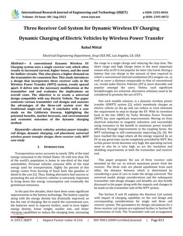
HelicalTenCoilsystemdescribedabovewassimulatedin MATLAB to study their flux distribution “Fig. 5” shows the intensityprofileofthefluxdistributionalongthewidthofthe road. If the vehicle drifts towards the extreme ends of the lane, the flux intensity is reduced to 75% of its original capacity, thereby not affecting the power at the receiver end byalargemargin.

This configuration consists of ‘two sets of three linearly closelyplacedlargehelicalcoilsplacedadjacenttoeachother, with four smaller coils placed between the voids created by thebiggercoils’.“Fig.4”showsthepictorialrepresentationof the structure mounted on road and depicted in scaled dimensions.


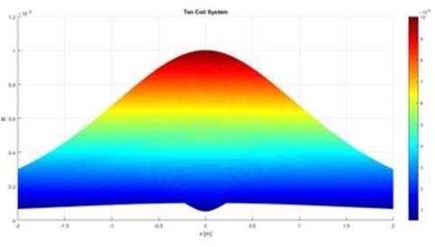
Thisconfigurationconsistsof‘fourcoilslinearlyplacedat the center of the lane’. “Fig. 6” shows the pictorial representationofthestructuremountedonroad,depictedin scale HelicalFourCoilsystemdescribedabovewassimulated inMATLABtostudytheirflux.


“Fig.7”showstheintensityprofileofthefluxdistribution along the width of the road. If the vehicle drifts towards the extremeendsofthelane,thefluxintensityisreducedto35% of its original capacity, thereby affecting the power at the receiverend.
The above discussed parameters are briefly summarized asbelow:
1) Flux linkage: The flux linkage observed in Three Coil receiver system is significantly higher than a single coil system as this provides an overall increase in the surface area incontactwiththe transmittingcoil thereby increasing thelinkage.
2) Continuity of charge: The continuity in flux linkage as mentioned above will provide a continuous charge to the Batteryascomparedtoatricklechargeasincaseofasingle receiver coil due to irregular flux linkages. The slope of the fluxintensityisconstantonthereceiverendside
D. Comparison of different cluster structures
The “Table II”, shows a comparative analysis of the three proposedclusterconfigurations.
3) Ease/Flexibility on Transmission End: The three receiver coil design reduces the design complexity for transmittingendcoilsastheclusterscannowbeplacedata certain distance instead of a continuous arrangement as in [9]. This reduces the copper and corresponding Initial investmentinvolvedinembeddingthedesignonroad.
4) Bulky Circuits: The maximum power transfer capability for a certain coil depends on the conductor thickness and the ferrite core properties. For same amount of power transfer, conductor thickness and corresponding core thickness will be higher for a single coil configuration. The entire power transfer capability gets concentrated on a singlecoilthusmakingitsdesignbulkier.

5) I2R Losses: Astheamountofcurrentdrawnismorefor a single coil configuration I2R losses are higher. For a three coil configuration the current drawn by each coil is less thereby reducing the losses and corresponding rise in temperature.
E. Selecting the best system configuration
AutoAligningofcoilsonthereceiverendsidecollectively with the 4 coils configuration on the transmitter side will remove the disadvantage of flux linkage problem as stated above in the four coil transmitter design. The set of three receivercoilsmountedonthecarisdesignedtodynamically change the location in a lateral axis, depending upon the positionofcarinthelane.Aseriesofsensorsmountedatthe
frontofthecardetectsthemagneticfieldandalignsthethree receivercoilsusingaspeciallydesignedhydraulicassembly.
6) No Load Losses: As discussed in section four, in three receiversystemonlyhalfofthecoilsarerunningatatimeas compared to single coil sytem, results in lower No-Load Losses.
7) Cost and Reliability: There is generally a trade-off between coil size, performance, and cost. Coil size and cost areinverselyrelatedsmallercoilsgiveabetterperformance, but at a higher cost. This means that a larger single coil geometry costs less than a coil array for a given charging area. Also the reliability of three coil configuration is more than the single coil system as in case of breakdown of the system.
8) Short Circuit Duty: Theshortcircuitcurrentpercoil is lessfor the three receiver coilsystemascomparedtosingle coil system, because now the current is distributed in a 3 coilsconfigurationandhencethecurrentpercoilisreduced.
VII. CASE STUDY
On analyzing on the above mentioned designs for the receivercoilmechanismandthecorrespondingTransmitting end design a case study is performed to assess the operability and characteristics in a Real Time situation. The EV data described in Section one shows the mileage of differentEV’swhereinitcanbeobservedthatinthepresent scenario no Electric vehicle is capable of performing Interstate travel or long commutes. The major drawback is the charging station accessibility and corresponding time involved at the charging station as per the level of charge. Implementation of Dynamic Wireless Power charging will allowtheusertoprovidea continuouschargetoEVthereby reduction in Battery size and increasing its mileage. Researchers at the Korea Advanced Institute of Science and Technology(KAIST)firsttestedtheirOn-lineElectricVehicle (OLEV)systemin2009[9].Increasingitsfurtherapplication, this will support interstate travel and will also reduce charging down time and eventually addressing the Range AnxietyofanEVuser.
A. Los Angeles- Sacremento scenario
The following case study analyzes the 380 mile I-5 freewaystretch betweenthecitycentersofLosAngelesand Sacramento, California. The particular roadway behaves as an ideal location for installing and implementing the Dynamic WPT design as it has one of the highest traffic densityandworksasamajorconnectionbetweentwoprime businessareasinCalifornia.Thepaperaimsatanalyzingtwo scenarios for enabling a Dynamic Wireless Power transfer systembetweentheabovementionlocations.Thissystemis designed keeping all the market available EV’s and their corresponding battery capacity and discharging rates as discussedinSectiontwo
The First scenario analyzes the segmented design for Lanes. A predetermined length of the lane is powered at a particular instant using the car position and various such segments are layered across the whole distance in a systematicapproach.Thefreewayisdividedintozoneseach havingaregionofchargingwhereintheTransmittercoilsare embedded in the road and provide the WPT charging to the car, this is followed by a Discharging zone which is the conventional roadway design. The distance between segments is calculated based on the discharge rates of different EV as mentioned in Section II, and calculated lane lengths areshownin“Table III”.This studyscenarioaimsat designing a universal lane charging system to ensure that
EV’s can traverse the desired distance irrespective of the make.
For different battery capacity and discharge rates as per Section two, lane length calculations are performed for a constant speed of 55mph. Considering an initial battery status of 85% at the start of the trip the following results were obtained. The results ensure a complete trip distance coveragewithdifferentresidualbatterystatusattheendfor furtherIntra-citytravel.
The segmented design aims at optimization of transmitting end section thus reducing the coil complexity, material used, ease of access and corresponding initial investment.
The second Scenario considers a fully powered freeway for the entire stretch of 380 miles. An entire lane termed as EV Lane is designed with transmitter coils embedded in the road that provides charge to the EV via WPT at all times as long as the EV stays on the lane. Combining this with the threecoilreceiverdesignacontinuousoptimumfluxlinkage is obtained such that the rate of charge is more or equal to rate of discharge based on the make. This ensure complete trip coverage with residual battery for further travel. This design shall promote mass transit using heavy EV’s that can bedynamicallypoweredviaWPT.
B. Ecological & Environmental Impacts:
As per KAIST, Korea OLEV Design [9] The Dynamic WirelessLanechargingsystemreducestheCarbonFootprint and overall cost of the transportation system. Implementationofthissystemon afreewayorhighwaywill increase the EV share in transportation. Assuming an increase in EV users by 30% over the freeway stretch considered in this Case Study it will reduce the CO2 and other emissions caused by (IC) cars considerably. Also the CO2 emissions are further reduced due to the modified design of 3 receiver coil. The reduced battery size and cost incurred compared to IC engine cars over energy consumed as per [9] clearly highlights the advantages of this system andlongtermeconomicbenefits.
VIII. CONCLUSION
Dynamic Wireless charging is an upcoming field with a huge scope of data collection and field analysis before implementing it on the large scale. .This paper introduces a three coil receiver end configuration with associated modifications and effects compared to existing single receiver coil configuration for charging of EV's dynamically usingWPT.Basedonsimulationsandcalculationsthisdesign methodholdsvalid.Inaddition,thispaperalsoexaminesthe transmitter side coil modifications, different cluster arrangements like four, six and ten coil configurations and their corresponding flux profiles. A four coil cluster configuration at the transmitter end with an auto alignment featureimplementedonthereceiverendcoilsisfoundtobe theoptimalsolution.Implementingthismodifiedtransmitter enddesignandreceiversidecombinationofWirelessPower transfer system, the output waveform so obtained, when simulated with a combination of rectifiers and six-pulse bridge circuits, resulted in similar waveform as that of a single receiver coil wireless charging circuit. The detail analysis of these wave-forms and the corresponding charging cycles is out of the scope of this paper. Analyzing the charging behavior of different EV's and developing a universaldesign,acasestudyisprovidedtosupplementthe above design with its calculations and environmental impacts. The author encourage the readers to look into differentconfigurationsandaimatuniversalchargingdesign forDynamicWirelesschargingofElectricvehicles.
ACKNOWLEDGMENT
Theauthorofthepaperwouldliketothank Universityof Southern California, and Smart Grid Regional Demonstration Project (SGRDP) conducted under American Recovery and ReinvestmentAct(ARRA)fundedbyLosAngelesdepartment
of Water & Power (LADWP) and US Department of Energy (USDOE)fortheirguidanceinresearchtowardsEVbehavior, chargingandpossiblescopeofDynamicCharging.
REFERENCES
[1] Annual Energy Outlook 2014 with Projections to 2040, U.S. Energy Information Administration (EIA) Annual Report,U.S.DepartmentofEnergy,April2014,Available online:http://www.eia.gov/Energyexplained/
[2] In-Soo Suh, Jedok Kim, “Electric Vehicle On-Road DynamicChargingSystemwithWirelessPowerTransfer Technology,” in Proc., Electric Machines & Drives Conference (IEMDC), IEEE International, 12-15 May 2013,Chicago,IL
[3] J. M. Miller and O. C. Onar, “Oak Ridge National Laboratoryinmotionwirelesspowertransfersystem,”in Proc., 1st Conference on Electric Roads and Vehicles (CERV’12),February2012,ParkCity,UT.
[4] O. C. Onar, J. M. Miller, S. L. Campbell, C. Coomer, C. P. White,andL.E.Seiber,“Anovelwirelesspowertransfer forin-motionEV/PHEVcharging,”inProc.,IEEEApplied Power Electronics Conference and Exposition (APEC), pp.3073-3080,March2013,LongBeach,CA.
[5] J. Kim et al., “Coil design and shielding methods for a magnetic resonant wireless power transfer system,” Proc.IEEE,vol.101,no.6,pp.1332–1342,Jun.2013.
[6] J. M. Miller, P. T. Jones, J. –M. Li, and O. C. Onar, “ORNL experience and challenges facing dynamic wireless power charging of EVs,”IEEE Circuits and Systems Magazine,Mayvol.15,no.2,pp.40-53,May2015
[7] N.P. Suh, D.H. Cho, and C.T. Rim, “Design of On-Line Electric Vehicle (OLEV),” Springer, CIRP Design Conference, 21st April,2010, France
[8] Musavi, F, Edington, M, “Wireless power transfer: A survey of EV battery charging technologies”, Energy ConversionCongressandExposition(ECCE),2012IEEE, pp.1804–1810,Sept.2012,Raleigh,NC
[9] O. C. Onar, J. M. Miller, S. L. Campbell, C. Coomer, C. P. White,andL.E.Seiber,“Anovelwirelesspowertransfer forin-motionEV/PHEVcharging,”inProc.,IEEEApplied Power Electronics Conference and Exposition (APEC), pp.3073-3080,March2013,LongBeach,CA.