International Research Journal of Engineering and Technology (IRJET) e-ISSN:2395-0056

Volume: 10 Issue: 08 | Aug 2023 www.irjet.net p-ISSN:2395-0072
International Research Journal of Engineering and Technology (IRJET) e-ISSN:2395-0056
Volume: 10 Issue: 08 | Aug 2023 www.irjet.net p-ISSN:2395-0072
Lokendra Alawa1 , Dharmendra Kurmi 2 ,
1Lokendra Alawa , Student , VITM Indore, INDIA
2Dharmendra Kurmi , Asst Prof, VITM Indore, INDIA ***
Abstract - Therearemanytypesofstructureswhichconstructingnowadays butframe structuresarethosestructures which are having the combination of beam, column and slab to resist the lateral and gravity loads. These structures are usually used to resist the large moments developing due to the applied loading.Inthis paper the bayframestructureof RCCRegularshapebuildingand LShapeirregularbuildingisstudiedindifferentseismiczones.
Thefollowingconclusionscanbedrawnfromstudythatbendingmomentalong x,y,andxy directionismoreinL Shape buildingthaninregularshapeRCCbuilding.AndtheMembraneandShearStressesarealsomoreinLShapebuildingthan in Regular shape RCC Building in different seismic zones 2 and 5 statically. While bending moment along x, y, and xy directionislessinLShapebuildingthaninregularshapeRCCbuilding.TheMembraneandShearStresses arealsolessin LShapebuildingthaninRegularshapeRCCBuilding indifferentseismiczones2and5dynamically.
Key Words: Moment,ShearForces,MembraneForces
1. INTRODUCTION
1.1 General: Many types of structures which are constructing now a days but the framed structures are the structureswhicharehavingthecombinationofcolumn,beam,andslabtoresistthegravityandlateralloads.
1.2 Typesofframedstructuresareasfollows:
1.2.1 Rigid Structural Frame
Rigidmeansabilitytoresistthedeformationofframe.Rigidframestructuresarethestructuresinwhichbeams &columnsareconstructedandtheyactcollectivelytoresistthemomentswhicharegeneratingduetoappliedload.
1.2.1.1 A pinned ended frame: In a rigid frame system we usually have pins at their support conditions. This frame system in which supports are pinned is considered to be non rigid frame if its support conditions are removed.
1.2.1.2. Fix Ended Rigid Frame Structure:Fixendedrigidframeisatypeofrigidframesystemsinwhich end conditionsareusuallyfixed.
1.2.2 Braced Structural Frames In Braced frame system, bracing are usually provided between beams and columns of frame to increase their resistance against the lateral loads andside forces due to applied horizontal load. Bracing is done by placing the diagonal members between the beams and columns of frame. This braced framesystemprovidesmoreresistanceagainsttheearthquakeandwindforces.Thisbracedframesystemismore effectivethanrigidframesystem
1.2.2.1 Gabled Structural Frame:
InaGabledframestructuresthepeakis atthetopofframe.Thesegableframessystemsareusedwherethere areheavyrainandsnowpossibilityisthere.
1.2.2.2 Portal Structural Frame
Portalstructuralframesusuallylooklikeadoor.Portalframesystemisinuseforconstructionofindustrialand commercialbuildings.
International Research Journal of Engineering and Technology (IRJET) e-ISSN:2395-0056
Volume: 10 Issue: 08 | Aug 2023 www.irjet.net p-ISSN:2395-0072
In framestructure itisa path through whichtheloadofa framestructureis transferred tothefoundations.In framestructures,generallytheloadpathis:
Advantages of Frame Structures
1. One of the best advantages of frame structures is their ease in construction. It is veryeasy to teach the labourattheconstructionsite.
2. Framestructurescanbeconstructedrapidly.
3. Economy is also very important factor in the design of building systems. Frame structures have economicaldesigns.
1.3 Disadvantages of Frames:
Thespanlengthsareusuallyrestrictedto40ftinframedstructure.Asthespansgreaterthan
1.4 Methods of Analysis of Frame:
Elastic analysis of frame deals with the study of strength and behaviour of the members and the structure at working and limit loads. Frames can be analysed by various methods. However, the method of analysis of frame adopted depends upon its configuration (portal bayor multibay) multi-storeyed frame, the types of frame, and Degreeofindeterminacy.Itisbasedonthefollowingassumptions:
1. The Relation between force and displacement in frame is linear. (I.e. Hook’s law isapplicable).
2. The Displacements in structure are extremely small as compared to the geometry of thestructure
2.1 General: In this Paper of research the bay frame building of concrete is analysed statically and dynamically underdifferentseismiczonesofearthquake.
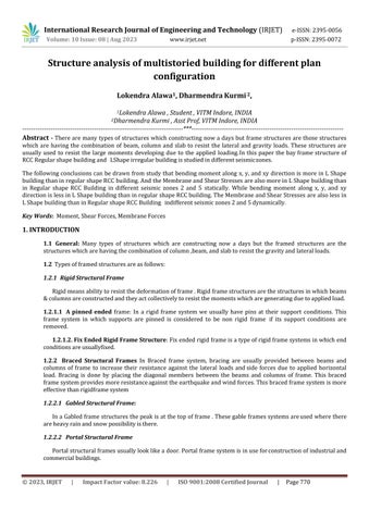
2.2PreliminarySectionsandmaterialsconsidered:Theplanareafortheproposedworkis20x30minwhichsize ofpanelsis5x6m.Thepropertiesofmaterialadoptedare:
2.2.1TheYoung’smodulusofelasticityofconcreteadoptedwas25,000MPawhilethePoisson’sratiowas0.2.
2.2.2 The preliminary sections of columns and beams were fixed on the basis of deflection criteria [i.e. span to depthratio].
3. Loads Considered:
3.3.1DeadLoad:Theloadsconsideredareasfollows:
Theself-weightofslab=0.2x1x1x25=5kN/m2
Loadconsideredduetofloorfinish=1kN/m2
3.3.2LiveLoad:LiveloadadoptedforfloorslabandroofaccordingtoIS875part-II:3kN/m2.
3.3.3 Earthquake Load: Response Reduction Factor: Depends on the perceived seismic damage of structure, it is characterised by ductile or brittle deformation; was taken from table-7(clause 6.4.2) IS1893 Part-1:2002. Importance Factor: Depends on the functional use of building characterised by hazardous consequences of its failure, it is taken from table-6 (clause 6.4.2) of IS1893 Part-1:2002. Time Period of undamped free vibration. In thepresentwork,parametersofearthquakeloadwereconsideredas:14
International Research Journal of Engineering and Technology
Load Combinations as considered for static analysis: The load combinations were adopted according to IS 1893
Part-1:2002&IS456:2000:
1.1.5(DL+LL)
2. 1.2(DL+LL+EQX)
3. 1.2(DL+LL-EQZ)
4. 1.2(DL+LL+EQZ)
5. 1.2(DL+LL–EQZ)
6.1.5(DL+EQX)
7. 1.5(DL–EQX)
8. 1.5(DL+EQZ)
9. 1.5(DL–EQZ)
10.0.9DL+1.5EQX
11. 0.9DL-1.5EQXHereX&Zarethedirectionsofearthquakeloadsconsideredintheanalysis.
GenerationofmodelusingSTAAD.Pro:
1Createanewfileandinputthepropertiesofmember’si.ecolumn,flatslabandshearwall.
2Applydifferentloadsonthestructureanddesigntheelementsandthenrunanalysis.
3Gotopostprocessingmodeandgettheresultsofmembersandelements.
4Viewtheoutputfiletogetthedesignresultsofallthemembersandelements
International Research Journal of Engineering and Technology (IRJET) e-ISSN:2395-0056
Volume: 10 Issue: 08 | Aug 2023 www.irjet.net p-ISSN:2395-0072
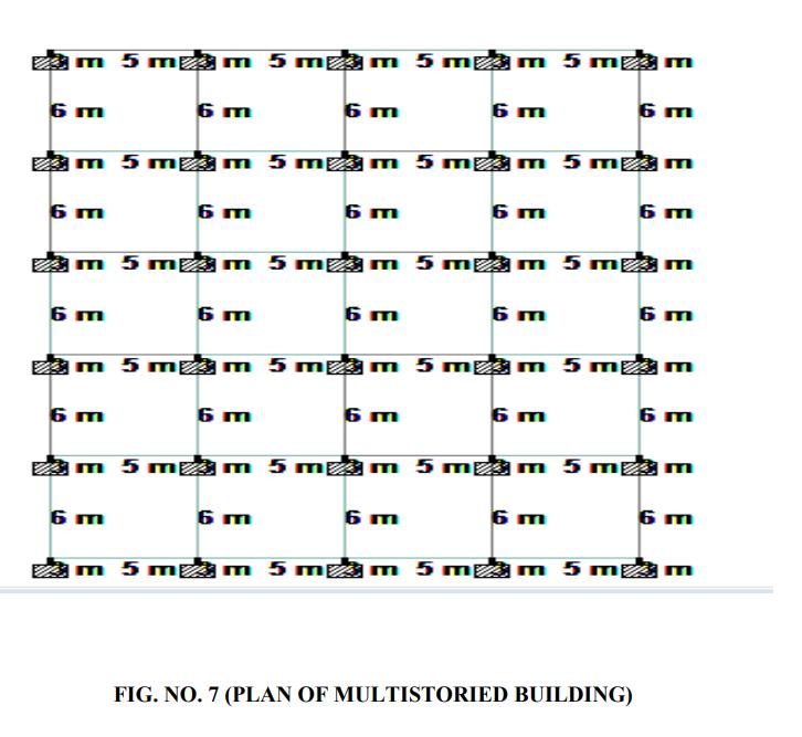
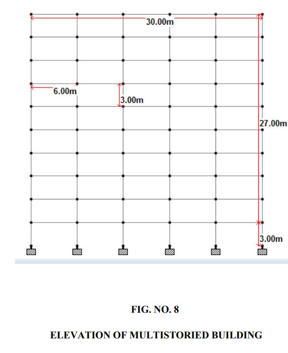
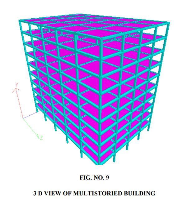
The Static and dynamic analysis of Bay Frame of Size 20*30 m is carried out for different seismic zones in 10 storey multi-storeyed building for finding the seismiceffects in multi-storeyed structure
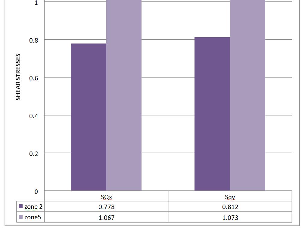
Shear Stresses for bay frame dynamically in different seismic zones
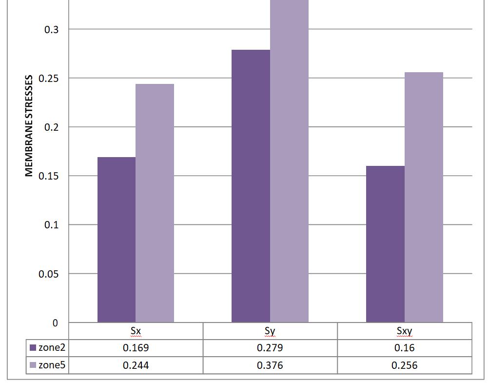
Membrane Stresses for bay frame dynamically in different seismic zones
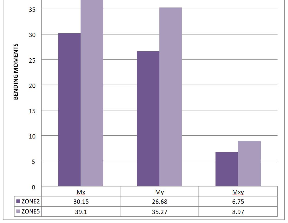
Bending Moment for bay frame dynamically in different seismic zones
| Page774
Theshearstressesinxandydirectioninbayframeincreasesdynamicallyinzone5thaninzone2
1. Themembranestressesinx,yandxydirectioninbayframeincreasesdynamicallyinzone5thaninzone
2. Thebendingmomentinx,y,andxydirectioninbayframeincreasesdynamicallyinzone5thaninzone2
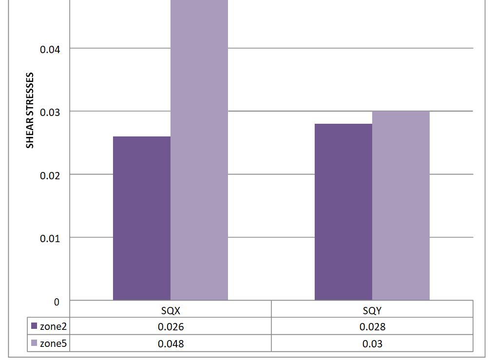
3. Theshearstressesinxandydirectioninbayframeincreasesstaticallyinzone5thaninzone2
4. Themembranestressesinx,ydirectionhasnovariationinzone2 andzone5andinxydirectioninbayframe increasesdynamicallyinzone5thaninzone2
5. Thebendingmomentinxandxyhasnovariationinzone2andzone5andbendingmomentinydirectionin bayframeincreasesdynamicallyinzone5thaninzone2
6. Frequencyvariationinzone2andzone5variesaboutmoreinzone5thaninzone2
7. Peakstoreyshearforzone2andzone5for10floorinxandzdirectionismoreinzone2thanzone5
8. Peakstoreyshearforzone2andzone5forbasefloorinxandzdirectionismoreinzone2thanzone5
9. Bending moment along x, y, xy direction is more in L Shape building than in regular RCC building in different seismiczones2and5statically.
10. embrane Stresses along x, y, xy direction is more in L Shape building than in regular RCC building in different seismiczones2and5statically.
11. ShearStressesalongx,ydirectionismoreinLShapebuildingthaninregularRCCbuildingindifferentseismic zones2and5tatically.
12. 13.Bendingmomentalongx,y,xydirectionisless inLShapebuildingthaninregularRCCbuildingindifferent seismiczones2and5dynamically.
13. MembraneStressesalong x, y,xydirection islessin L Shapebuilding thaninregularRCCbuildingindifferent seismiczones2and5dynamically.
14. Shear Stresses along x, y direction is less in L Shape building than in regular RCC building in different seismic zones2and5dynamically.
1. Nasratullah Zahir, Dr. Vivek Garg: StaticandDynamicAnalysisofR.CBuildingFramewithInfill.
2. Mohd Mohibur Rahman, Banulatha.G.N, Dr. Narayana.G, Manu.J: studied the behaviour of R.C.C frames structureswithdifferentfloorsystemsundertheeffectoflateralloads.
3 Shrikant Harle: analyzedamulti-storeyedR.c.c.buildingwiththehelpofNISAsoftware.
4 Ky Leng, Chatpan Chintanapakdee, and Toshiro Hayashikawa: verifiedtheRSAprocedureprescribedinthe currentThaiseismicdesigncodewhichisbasedonASCE7-05
5 Rajib Kumar Biswas, Md.Meraj Uddin, Md.Arman Chowdhury, Md.Al- Imran Khan: workwasconcernedto increase lateral stiffness of flat plate structure and to minimize the displacement of the structure under lateral loading
6 Umesh. N. Karadi and Shahzad Jamil Sardar: studied 25storey building inzone Vandanalyzed by changing locationsofshearwallfordeterminingparameterslikestoreydrift,storeyshearanddisplacement.
7 Ermiao LIN1 and Pankaj: Nonlinear Static and Dynamic Analyses the Influence of Material Modelling In ReinforcedConcreteFrameStructures
8 Filip C. Filippou, Angelo D'Ambrisi, Ahmad Issa: Nonlinear Static and Dynamic Analysis of Reinforced ConcreteSubassemblages