BEAM COLUMN JOINT ANALYSIS FOR VARIOUS LOADING USING FINITE ELEMENT METHOD FOR STEEL STRUCTURE
Dr. Pradeep P. Tapkire1 , Vinayak A. Hanchate2, Atul S. Chandanshive31H.O.D. Civil Dept., N.B. Navale Sinhgad College of Engineering, Solapur, Maharashtra, India-413255
2Research Scholar at N.B. Navale Sinhgad College of Engineering, Solapur, Maharashtra, India-413255
3Lecturer Civil Dept., Solapur Education Society’s Polytechnic Solapur, Maharashtra, India-413002 ***
Abstract - This paper presents a comprehensive finite element analysis (FEA) study on the behaviour of beamcolumn joints in steel structures subjected to two types of load combinations. The load combinations considered include dead load, live load, wind load, and dead load, live load, earthquake load. Furthermore, three types of column configurations and two types of beam sections are analyzed to investigate their influence on the structural response
Key Words: Beam column joint, FEM.
1. INTRODUCTION
The ideal beam-to-column couplings are pinned or completely stiff, and this assumption has long been made whendesigningsteelportalframes.
The performance of a framed structure depends on the integrityof the jointsaswell aseachindividual structural component.Thejointsarethemostimportantcomponentof the framed structure because they ensure structural continuity.Thejointsarestrongenoughtotransfertheload fromastructuralmembertotheendofthememberinorder topreventstructuralfailure.
When using the ideally pinned connection, the beam and column cannot transmit moments; as a consequence, the connections lack rotational stiffness and cannot transmit movements,whiletransmittingaxialandshearforces.Full rigid joints transmit all forms of loads between beam and column because they have rotational compatibility. Their behaviourisdecoupledfromthestructureduringanalysisof these joints Although this simplifies the analysis and structuraldesignprocesses.
Inordertostudyanddesignthejoint,thesejointbehavior modelsmustbeincludedintostructuralanalysissoftware.
1.1 AIM & Objective
Thispaperaimstoinvestigatebeamtocolumnjointinsteel structuresusingfiniteelementmodelling.
The following points are considered to carry out finite element analysis of the beam to column junction in steel structures:
1. Study of beam to column joint under different loading.
2. Thevariouscrosssectionisconsideredforanalysis byusingfiniteelementmethod.
3. Finite element analysis is considered for various columnconfiguration.
Non-dimensional details will be prepared based onthe resultsobtainedbydifferentcombinationofparameter.
2. Literature review

Hassan A. Saab [1] presentedworkwasdoneoncreatinga finiteelementtechniqueandusingittoconductbehavioral researchonsteelframesduringfirecircumstances.
Elsayed Mashaly, Mohamed El-Heweity, Hamdy AbouElfath, Mohamed Osman [2] researcher developed an intuitive andaccuratethree-dimensional(3D)finiteelement model (FE) in order to properly predict the behaviour of beam-to-columnconnectionsinsteelframeswhensubjected tolateralstresses Theboltedextended-end-plateconnection was shown to be a crucial component of beam-column junctions.Theextended-end-plateconnectionischosenfor itscomplexityintheanalysisandbehaviorduetothenumber ofconnectioncomponentsandtheirinheritablenon-linear behavior. Twoexperimentaltestsfromtheliteraturewere utilized to verify the finite element model. Researchers compared the results of the experimental model with the proposedfiniteelementmodel.
R.A. Hawileh, A. Rahman, H. Tabatabai [3] developed a detailed three-dimensional (3D) nonlinear finite element model for the purpose of analyzing the reaction and forecasting the behavior of a precast hybrid beam-column connection subjected to cyclic stresses Using 3D solid components and surface-to-surface contact elements betweenthebeamandcolumnfaces,theprecastjunctionwas modeled. The model accounts for the nonlinear material
behaviorofconcreteaswellasthepre-tensioneffectinthe post-tensioning strand. At all loading stages, a good agreement between the model response and the experimentaltestfindingswasfound.Theconnectionfailed asaresultofthemildsteelbarsbreaking.Stressandstrain fieldsinthemild-steelbarsatthebeam-columncontactwere derived using the examined model to forecast this failure scenario.
M.R.Mohamadi-Shoore,H.GhafariandM.Amankhani[4] describes a Finite Element Modeling (FEM) of RHS-based splice beam connectors that were just bent. SUT-DAM software wasusedtocreatea THREE-DIMENSIONAL (3D) finiteelementmodelconsistingofanend-plate,fourbolts,a weld,andthewebofabeam.
Vishawadeep Shivaji Ghodajkar, Dr. R.M. Sawant [5] researcher observed that top and seat angle connections causesmallerstrainsthandoublewebangleconnectionsand extended end plate connections when various loads and accelerationsareappliedtothethreeseparateconnectionsin oneofthoseconnections.
Kuldeep Kaushik, Avadesh Kumar Sharma, Rishi Kumar[6] researchers states that the flush end-plate connectionismoregoal-orientedthantheextendedend-plate connection, in order to join members in bridge and shade structuresefficientlyandeffectively,
Chintamani N.Khadake,PrashantM.Pawar[7] conducted RCC structural analysis and design. Following that, FEA software was used to examine one of the outside beam columnjoints.
Kathirvelmurugan K R V, Satheshkumar K [8] describes Finite Element Model (FEM) for the efficient analysis of structuralconnectionsinordertodecreasethecomplexityin connection design. For the examination of connections, a novel method known as Component Based Finite Element Model(CBFEM)wasintroducedinthisarticle.Thistechnique enhancestheconnectionbydecreasingstructuralflawsand raisingmomentbearingcapability.
Balamuralikrishnan R., Saravanan J. [9] researchersused ABAQUSsoftwaretoquantitativelyanalyzethebehaviourof anexternalbeam-columnconnectionthatincludedinternal GFRP reinforcements under various material, loading, and supportcircumstances.Themechanicalpropertiesofthese reinforcements are well documented and are utilized for modellinganalysis

3. PROBLEM FORMULATION
The various finite elements were considered in this projectareasfollows:-
C1-Single“I”section.
C2
Backtobackchannelsection
C3–ToetoToechannelsection
B1–Single“I”section
B2–“I”sectionwithtopplate.
Threealternativecolumngeometriesandtwodifferent beamgeometriesweretakenintoconsiderationforthestudy ofthebeamcolumnjunction.
Eachfloorheightis4meters,andaG+4building*witha spanof3,4,5,and6meterswasexamined.
Todeterminethemaximumbendingmomentonthebeam and the axial force on the column, the Staad Pro ver. 8 programwasutilized..
Load combination: -
Inthiscasetwoloadcombinationswereconsideredare asfollows:
1.DL+LL+WL
2.DL+WL+EQ
3.3 Analytical Work: -
GeometrySpecificationsoffiniteelementsareasfollows:
B1-ISMB250@37.3kg/m
B2 - ISMB 250 @ 37.3 kg/m, width of plate 150 mm & thicknessofplate10mm
C1-ISHB300@58.8kg/m
C2-ISMC250@30.4kg/m,spacing10mmbacktoback
C3-ISMC250@30.4kg/mspacing10mmtoetotoe
Aftertheconsiderationofspecificationtwotypesofload combinations were taken into account, and 48 models in Staad Pro were createdaccording to theabove-mentioned span.

Methodology
CalculationsofLoadcombinations:-
1. DL
1.1 SelfWeight
1.2 Memberload(Wallload)
HeightofWall=3.75m,Widthofwall=0.169m
Memberload=20x0.169x3.75=12.65KN/m
1.3 FloorLoad=1.5N/m
2. LiveLoad=2KN/m
AutoLoadCombinationinStaadprover8asfollows:
1. 1.5DL+1.5LL
2. 1.2DL+1.2LL+1.2WL
3. 1.2DL+1.2LL-1.2WL
4. 1.2DL+1.2LL
5. 1.5DL+1.5WL
6. 1.5DL-1.5WL
7. 1.5DL
8. 0.9DL
4.3 Cases Considered
Asperdesigndeformationwerecalculatedatdifferent threetypesofJointsofbeam&columnconsideredasfollows:
1. Joint1–EndColumn
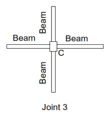
2. Joint2–AtMiddle(‘T’)
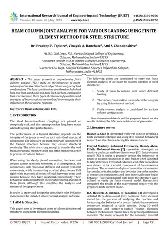
3. Joint3–AtCentre
1.Joint1–Endcolumnweretwobeamsareconnectedat thatjoint.
2.Joint2-Atmiddle(T)werethreebeamsareconnected atthatjoint
3.Joint 3 -At Centre were four beams are connected at joint
4. RESULTS
Inordertoanalyzethebeam-columnjunction,twoformsof loading DL,LL,WLandDL,LL,EL andsixdistincttypes ofgeometryweretakenintoaccount.Usingaspreadsheet, thedimensionsofthebeamandcolumnaredeterminedfor various spans and heights. The ANSYS finite element program is used to resolve the various spans with fixed heights for varied geometries. For the scenarios under consideration, the maximum deformation, maximum principal stresses, and minimum principal stresses are determined, and the results show the % variation for deformationandstresses,
Effect of different loading on deformation and stress for various beam column combination.

1. Effect of different loading on deformation.
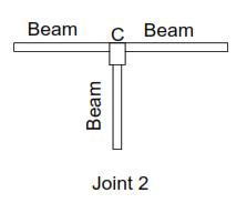
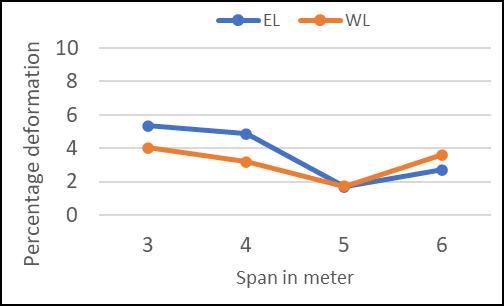
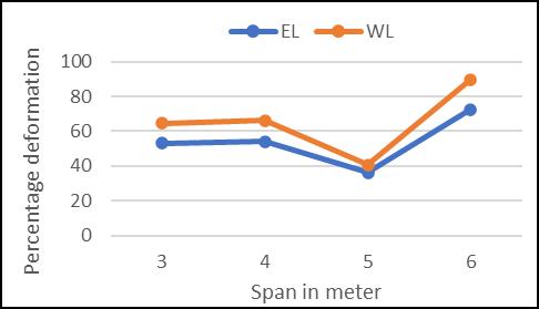
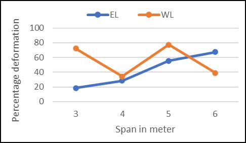
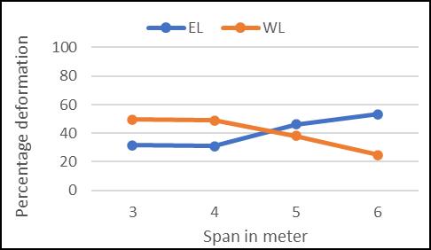
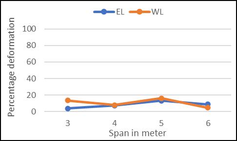
FromGraphG1throughG6,therelationshipbetweenvaried loads and deformation for various beam column ccombinationsisdisplayed.
Graph G1: Variation of percentage deformation of B1C1 beam-column joint.
Graph G4: Variation of percentage deformation of B2C2 beam-column joint.
Graph G5: Variation of percentage deformation of B1C3 beam-column joint.
Graph G2: Variation of percentage deformation of B2C1 beam-column joint.
Graph G3: Variation of percentage deformation of B1C2 beam-column joint.
Graph G6: Variation of percentage deformation of B2C3 beam-column joint.
From various graph G1 to G6, the deformation of various beamcolumncombinationaccordingtospananddifferent loadingareobserved.
From the above graph it is noted that wind load is predominant in some cases specially beam column joint combinationwithC1typecolumn.
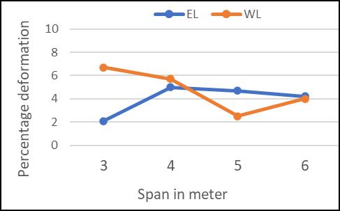


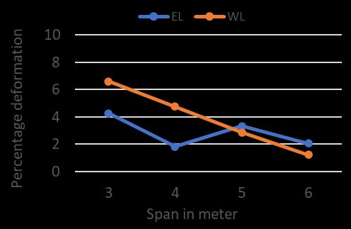

Beam column joint with C2 type variation shows more deformationforwindloadcases.
Earthquakeforcesareslightlyeffectiveforabeamcolumn jointswithcolumnC3variation.
Spanofbeamisalsoaffectingthedeformationfordifferent loading. Especially span lower than 8m showing higher deformationsforvariousbeamcolumnjoints.

Beam column joints with 5m span shows comparatively lowerdeformationforallcombinationsalsoeffectofloading isnotmuchdifferfor5mspan.

2. Effect of different loading on maximum stress (tensile)
Graph G12: Variation of percentage maximum stress (tensile) of B2C3 beam-column joint.
Maximumtensilestressesgettingaffectedbecauseofvarious loadingandspan.Thevariationisplottedasaboveingraph G7toG12.
Column type C1 shows more stress for wind load in comparisonwithearthquakeloadforlowerspan.


WithC2typeofcolumnvariation,tensilestressesvaryingas pertypeofbeamforspecificallylowerspan.
ForC3typeofcolumnwindloadinducesmoretensilestress ascomparetoearthquakeload.
Spanofbeamisalsoaffectingtensilestressinduced.Similar to deformation 5m and above span shows comparatively lowerstressinB1typeofcombination.

ForB2typeofcombinationshigherspanshowshigherstress induced.
3 Effect of different loading on maximum stress (compressive)
Graph G14: Variation of percentage maximum stress (compressive) of B2C1 beam-column joint
Graph G13: Variation of percentage maximum stress (compressive) of B1C1 beam-column joint.
Graph G15: Variation of percentage maximum stress (compressive) of B1C2 beam-column joint
Graph G16: Variation of percentage maximum stress (compressive) of B2C2 beam-column joint.
Graph G17: Variation of percentage maximum stress (compressive) of B1C3 beam-column joint.
beingconnectedandinC3columnconfigurationmaximum tensilestressinducedbecauseofearthquakeforces.
Fromthevariationofdifferentloadingitisconcludedthat windloadispredominantforlowerspan(below5m)joint withC1columnconfiguration


REFERENCES
[1] Hassan A. Saab (1990), “Non-linear finite element analysisofsteelframesinfireconditions”,Universityof Sheffield
[2] ElsayedMashaly,MohamedEl-Heweity*,HamdyAbouElfath, Mohamed Osman (2010), “Finite element analysisofbeam-to-columnjointsinsteelframesunder cyclicloading”,AlexandriaEngineeringJournal.
[3] R.A. Hawileh, A. Rahman, H. Tabatabai (2009), “Nonlinear finite element analysis and modeling of a precast hybrid”, University of Wisconsin-Milwaukee, AppliedMathematicalModelling34(2010)2562–2583.
[4] M. R. Mohamadi-Shoore, H. Ghafari, M. Amankhani (2013), “Finite Element Modeling of RHS Splice Beam Bolted Connections”, Indian Journal of Science and Technology.
[5] Mr. Vishawadeep Shivaji Ghodajkar, Dr. R.M. Sawant (2018), “FEM Analysis of Steel Beam Column Joint by using Cantilever Weight and Acceleration”, Journal of CeramicsandConcreteSciencesVolume3Issue3.
Graph G18: Variation of percentage maximum stress (compressive) of B1C3 beam-column joint
G13toG18showsvariationofcompressivestressalongwith spanforvarioustypeofloading.
For all combinations of beam column joints, compressive stressispracticallysameforbothwindloadandearthquake load.
ForC1columntypeslightvariationsareobservedonlower sideforearthquakeload.
SimilartothatC2columncombinationsshowslightlylower stressinducedforbothtypeofloading.
C3typeofcolumnshowspracticallysamestressinducedfor bothloadingcondition.
5. CONCLUSIONS
InC1columnconfigurationofbeamcolumnjointwindload induces higher tensile stress for lower span and in C2 column configuration induced stress varies with type of
[6] Kuldeep Kaushik, Avadesh K. Sharma, Rishi Kumar (2013),“AReviewonFiniteElementAnalysisofBeamto ColumnEndplateBoltedConnection.”,IOSR Journalof MechanicalandCivilEngineering(IOSR-JMCE)e-ISSN: 2278-1684,p-ISSN:2320-334X,Volume8,Issue1(Jul.Aug.2013),PP97-103.
[7] Mr. Chintamani N. Khadake, Dr. Prashant M. Pawar (2020),“Finiteelementanalysisofbeamcolumnjointin reinforcedconcretestructure.”InternationalResearch JournalofEngineeringandTechnology(IRJET)e-ISSN: 2395-0056Volume:07Issue:07|July2020.
[8] Kathirvelmurugan K R V, Satheshkumar K. (2016), “ANALYTICAL & EXPERIMENTAL STUDY ON STRUCTURAL STEEL CONNECTIONS USING COMPONENT BASED FINITE ELEMENT MODEL”, InternationalJournalofEngineeringScienceInvention Research&Development;Vol.IIIssueXIMay2016
[9] Balamuralikrishnan R., Saravanan J. (2019), “Finite element analysis of Beam – Column joints reinforced withGFRP reinforcements.”, Civil EngineeringJournal Vol.5,No.12,December,2019.