Lateral Load Analysis of Elevated Intze Water Tank By STAAD.PRO
 Gururaj1 , Dr.Shruti G2
1M. Tech Student, Civil Engineering Department, PDA college of Engineering. Kalaburagi, Karnataka, 2Assistant Professor, Civil Engineering Department, PDA college of Engineering, Kalaburagi, Karnataka, India ***
Abstract –Water is one of the important elements in our life. As water is used in many different fields like distribution of drinking water, agriculture, industry, fire fighting etc. All these purpose needs various types of flow throughout the year according to the use. We need to store the water to maintain the flow of water. For this purpose we have to construct an elevated water tanks. INTZE water tank is one of the large structures to store the water and these types of structure are build for long term use. These types of structures need to resist the strong wind load and earthquake loads. In this project total of three models were prepared one model with empty water condition, second model with full water condition and third model with half water condition with presence of wind in different terrain category. In this project the parameters displacement, bending moment and shear force is checked. The maximum values obtained in the full tank condition. With regard to terrain categorization, various models have been used in the comparison.
Key Words: ElevatedIntzetank,WindAnalysis,StaadPro, TerrainCategory
1. INTRODUCTION
Waterisessentialforthesurvivalofeverytypeofanimalin the planet Intze type are frequently utilized as water reservoirs ThebasiccomponentsofanIntzetankareaTop Dome(roof),acylindricalwall,andafloorslabmadeupofa conical dome and a bottom spherical dome. Both the movementofthetankwithregardtothewaterinsideitand themovementofthetankwithrespecttothegroundmust beconsideredwhenanalyzingthedynamicbehaviorofthese tanks. The current design of high water tank support structuresisextremelyvulnerabletolateralstressesasitis constructedforwindforces.
1.1 Water Tanks in General and WaterTankTypes:
Watersupplyprojectsarecrucialforthenation'ssocialand industrialgrowthandhaveattractedalotofinterestinrecent years across the globe. Depending on how much water is used,watertankscomeinavarietyofcapacities.Basedon wheretheyarelocated,watertanksaredividedintothree types.:
1.Watertanksburiedunderneath
2.Thetankissittingontheground.
3.Watertanksthatareelevated.
According to their shape, water tanks are also categorized:

1.Circulartanks
2.Rectangulartanks
3.Intzetanks
4.Circulartankwithconicalbottom
5.Sphericaltanks
1.2 Intze Tank Elements
Top dome:Ingeneral,wesupplya110to150mmthicktop dome with reinforcement throughout the latitudes and longitudes.Thedome'sriseistypicallyone-fifthofitslength.
Top ring beam:Thereisameridionalthrustappliedtothe top ring beam. The beam is made to accommodate hoop stressbroughtonbywaterload.
Cylindrical walls: Theprincipalforceactingonthewallis hooptension,whichisbroughtonbywaterpressure.So,the wallisbuilttoaccommodatehooptension.
Ring beam at the bottom: This ring beam was installed between the cylinder wall and the conical slab. The ring beamisemployedtooffsetthehorizontalcomponentofthe cylindrical wall's reaction to the conical wall. The bottom ringbeam'spurposeistosupportthetensioncreatedbythe hoop.
Conical slab:Theslabissubjectedtobothmeridionalthrust and hoop tension. Fluid pressure is what causes the hoop
tension, and vertical pressure is what causes meridional. Consequently,theslabshouldbebuiltsafely.
Bottom dome: Thebottomslabcouldbedome-shapedor spherical. A circular girder serves as the support for this slab.
Circular girder: The girder should be built to support stresses from the conical slab (inclined thrust) and the bottomdome(outwardthrust).Itshouldbebuilttoendure thetorsionandbendingmomentssinceitwillbeputonthe columns.
Columns: The columns are built to handle the overall transmission from the tank. As for wind and earthquake loads, columns are also intended for those. Bracings are positionedperiodicallyincolumnstofendofftheeffectsof windandearthquakes.
Foundations: In general, to support the all columns combined footing is adopted. To support a circular girder andcircularslabaredesign.
Wind Load: TheIScodeIS875(part3)isusedtodetermine windpressureactingatanyheight.ThebasicWindSpeedVb isobtainedfromthewindmapasshownintheIS875(Part 3) 2015. The following are some factors that affect the designwindspeedVz:
1.Riskcomponent(k1)
2.HeightandTerrainFactor(k2)
3.Topography(k3)
4.ImportanceFactorforCyclonicRegion(k4)
Accordingtothenormalwindspeed,thereare6zones,zone ItozoneVI. Thetypicalwindspeedshouldbeadjustedto accountforthefollowingparametersinordertodetermine thewindspeedinheightforthechosenconstruction.Based on the code for wind obstruction, there are four different types of terrain. Based on the depicted map of the Indian Windregion.Indiahasbeenfoundtobeseparatedintosix windzones,suchasZoneIandZoneVI,fullybasedonthe fundamentalwindrhythm.
Followingarethestepsforcalculatingdesignwindspeedat anyheight:
Vz = Vb k1 k2 k3 k4
Todeterminethedesignwindpressureatanyheightabove meangroundlevel,therelationshipbetweenwindpressure andwindvelocitymustbeused.
Pz = 0.6 Vz²
Where,Pz=DesignwindpressureinN/m2 atheightz
Vz=Designwindvelocityinm/secatheightz
2. Structural Details:
FollowingsaretheparametersofIntzewatertank
3. WIND ANALYSIS RESULTS:
3.1 Comparison of displacement among all three cases
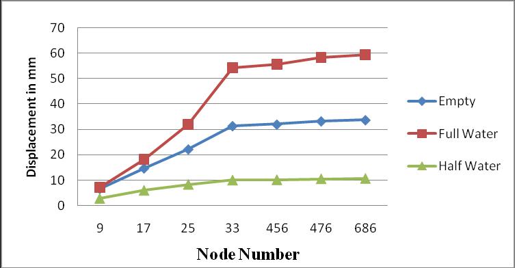
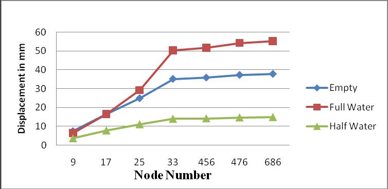

Table 1: DisplacementinmminX-directionforModel-1, Model-2andModel-3in terrain category-I
Table 3: Displacement in mm in X-direction for Model-1, Model-2andModel-3in terrain category-III
Graph 1: DisplacementinmminX-directionforModel-1, Model-2andModel-3Interraincategory-I
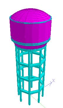
Table 2: Displacement in mm in X-direction for Model-1, Model-2andModel-3in terrain category-II
Graph 3: DisplacementinmminX-directionforModel-1, Model-2andModel-3interrain category-III
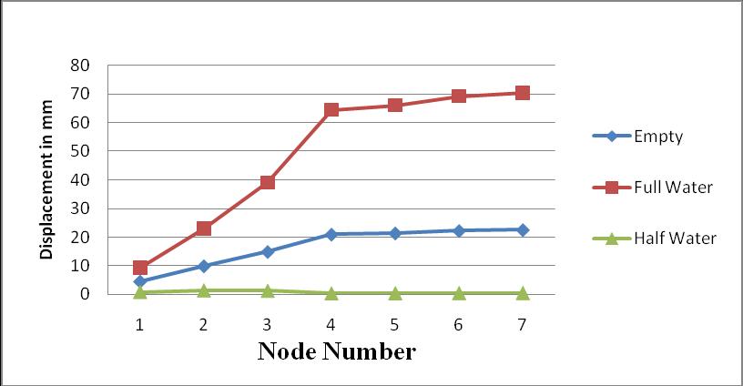
Table 4: Displacement in mm in X-direction for Model-1, Model-2andModel-3interraincategory-IV
Graph 2: DisplacementinmminX-directionforModel-1, Model-2andModel-3interraincategory-II
Graph 4: DisplacementinmminX-directionforModel-1, Model-2andModel-3interrain category-IV
3.2 Comparison of bending moment among all three cases:

Table 5: BendingMomentinKNminX-directionforModel1,Model-2andModel-3in terrain category-I
Graph 5: BendingMomentinKNminX-directionfor Model-1,Model-2andModel-3interraincategory-I
Table 6: BendingMomentinKNminX-directionforModel1,Model-2andModel-3in terrain category-II
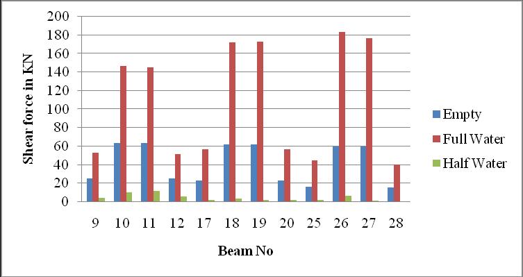
3.3 Comparison of shear force among all three cases:


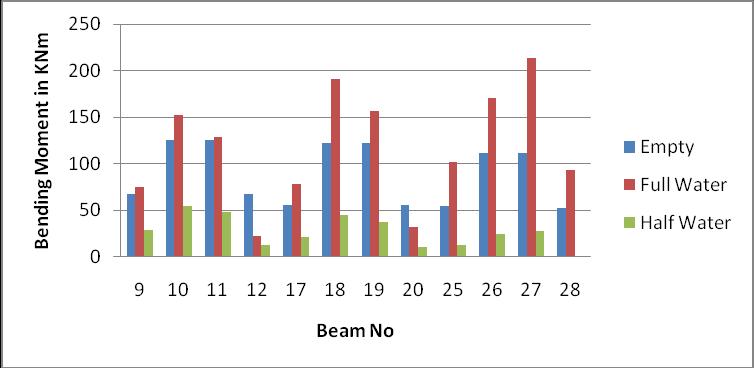

Table 9: ShearforceinKNinX-directionforModel-1,Model2andModel-3in terrain category-I
Graph 6:BendingMomentinKNminX-directionfor Model-1,Model-2andModel-3interraincategory-II
Table 7: BendingMomentinKNminX-directionforModel1,Model-2andModel-3in terrain category-III
Graph 9: ShearforceinKNinX-directionforModel-1, Model-2andModel-3interraincategory-I
Table 10: Shear force in KN in X-direction for Model-1, Model-2andModel-3in terrain category-II
Graph 7: BendingMomentinKNminX-directionfor Model-1,Model-2andModel-3interraincategory-III
Table 8: BendingMomentinKNminX-directionforModel1,Model-2andModel-3in terrain category-IV
Graph 10: ShearforceinKNinX-directionforModel-1, Model-2andModel-3interraincategory-II
Table 11: Shear force in KN in X-direction for Model-1, Model-2andModel-3in terrain category-III
Graph 8: BendingMomentinKNminX-directionfor Model-1,Model-2andModel-3interraincategory-IV
Graph 11: ShearforceinKNinX-directionforModel-1, Model-2andModel-3interraincategory-III
4. Observation:
1. For each of the three models in this project's various terraincategories,windanalysiswasperformed.
2.Windforcesappliedinxandzdirection.Alltheloadsare assignedtothemodels.
3.Inmodel-1thedisplacementismaximumfortheterrain category-1 and values goes on decreasing for other three terraincategory.
4. Comparingthedisplacementinfulltankconditiontothe otherterraincategories,wecanobservethatitisgreater.
5.Thedisplacementismaximuminmodel-2i.e.watertank fullcondition
6. It is observed that the Bending Moment is more when thereiswaterpressurefrominsidethetank.
7.ItisalsonoticedthatBendingMomentisreducedwhen thereishalfwaterpressurefrominsidethetank.
8.Itisobservedthattheshearforceismaximumwhenthe tank is empty for the beams at lower level( i.e. 9,10,11,12,17,18,19,20) and the Shear force is maximum when water pressure from inside for beams at upper level(25,26,27,28)forterraincategory-I
10. It was noticed that the shear force is minimum for all beams when there is half water pressure from inside for terraincategory-I.
11. It is seen that the shear force is maximum for beam 9,10,11,12 and for remaining beam the shear force is minimumforterraincategory-II.
12. It was noticed that in case of terrain category-III, the Shear force is maximum when there is tank with full of
water, and shear force is minimum for the case with no waterpressureandhalfwaterpressurefrominside.
13. In case of terrain category-IV, the shear force is maximumforthetankwithfullofwater,andminimumfor thecasewithnowaterpressurefrominside,andhalfwater pressurefrominside.
5. Conclusion:
1.InthisprojectwehaveseenthatIntzetankwithfulltank conditioniscritical
2. It is conclude that as the displacement decreases from categoryItoIVduetheterrainroughnessfactorwithterrain category.
3.Theparameterslikedisplacement,bendingmomentand shearforcesarecalculatedwithrespecttodifferentterrain category
4.Comparisonofthreedifferenttankfillconditionwiththe differentterraincategoryhasbeendone
REFERENCES
1.Kulvendra Patel “Wind and Seismic Analysis of Elevated Tank using Staad Pro” International Research Journal of EngineeringandTechnology(IRJET) Volume:05Issue:10| Oct2018.
2.KetanAshokAkolkar,K.S.Patil,Dr.N.V.Khadke“AReview Paper On Wind Analysis Of Elevated Intze Tank Using Different Arrangements Of Bracing System” International Journalofcreativeresearchthought Volume10,Issue5May 2022
3.Ms.SusmithaS.K,Mr.PradeepKaranth“WindAnalysisOf Elevated Water Tank For Different Bracing System” International Research Journal of Modernization in Engineering Technology and Science Volume:03/Issue:08/August-2021.
4.Swati,MrSumit“EffectOfWindLoadOnElevatedWater TankOfIntzeType:An OverviewInternationalJournalof EngineeringSciences&ResearchTechnology May,2018
5 AatishKumar,R.K.Pandey,C.S.Mishra“WindEffectson Overhead Tank under Different Soil Parameters, International Journal of Engineering and Advanced Technology(IJEAT)Volume-2,Issue-6,August2013
6. Dr. P. D. Hiwase, Dr. P. P. Dahale, Dr. A. A. Mehta, Er. BhaveshRajeshSahn“EffectofWindandSeismicForceson IntzeTypeWaterTankforDifferentasperIndianStandards Zones31stDecember2019
7. S. Deepika , Gugulothu.Swarna “Design and Analysis Of Intze Type Water Tank For Different Wind Speed And
SeismicZonesAsPerIndianCodes”InternationalJournalof AdvancedtechnologyinEngineeringandsciencevolume-4 issue-10October2016
8.KetanAshokAkolkar,K.S Patil“AReviewPaperOnWind Analysis Of Elevated Intze Tank Using Different ArrangementsOfBracingSystem” International Research Journal of Modernization in Engineering Technology and ScienceVolume:04/Issue:04/April-2022
9. Prof. Patel Nikunjr , Jugal Mistry “Analysis of circular watertankstressunderhydrostaticloadingbyusingstaad prosoftware”,indianjournalofresearchVolume:5|Issue: 9|September2016
10. Mainak Ghosal “Water Tank Analysis Using STAAD PRO”InternationalTransactiononEngineering&Science, Volume1,Issue2,January2019