
Comparative Analysis of RCC and Composite Building Subjected to Lateral Load
Shivaling Tadkal1 , Shivanand V Chanaveere2
Abstract -Steel-concretecomposite-structuresareimportant in modern building because of their synergistic benefits.These constructions provide outstanding load carrying capacity, structural efficiency, and design flexibility by combining the high tensile strength of steel with the compressive strength of concrete. They are resistant to dynamic loads such as earthquakes and wind forces, making them excellent for resilient and safe construction. So when compared to RCCStructures, steel concrete composite -structures are being more-popular. In this paper, an-attemptwasmadetoevaluate and compare the performance of G+25 storey’s RCC and Composite- Structures subjected to seismic-load using ETABS 2020 Software. A total of six models were prepared, 3 models are of RCC and 3 models are of composite buildings, in which lateral load-resisting systems, such as bracings and shear walls are installed. The buildings-arelocatedinseismiczone-V and soil is medium. Response-spectrum Analysis is used for both RCC and Composite-Structures. Displacement, StoreyDrift, Base-shear and Time Period are considered as parameters. When compared to RCC, composite structures performed better.
Key Words: Composite-Structures, ETABS, Response SpectrumAnalysis,Bracings,ShearWall
1. INTRODUCTION
Theseismic-performanceofstructuresisacrucial factor in structural engineering, especially in earthquakeprone areas. The choice of building materials and constructiontechniqueshasabigimpactonhowresilienta structure is to seismic pressures. Seismic resilience of structuresisamajorchallengeinearthquake-proneareas. Because of their various characteristics and engineering properties, reinforced concrete (RCC) and compositestructures have emerged as two key competitors for withstandingseismicloads.
Compositeconstructionscombinetheadvantagesof manymaterialstoimproveperformance.Theyofteninvolve the combination of concrete with steel or other highstrength elements. This combination improves structural efficiency by allowing the structure to benefit from the strengthsofeachconstituentmaterial.Composite-structures havehigherrigidityandductilitythantypicalRCCstructures.
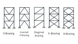
A Bracing system is a structural element to resist lateral forceslike-wind,andotherloadsthatcancausethebuilding toswayorcollapse.

Shearwallisastructuralelementwhichprovidestructural support that resists lateral forces such as earthquakes or heavy wind. These walls prevent the building from collapsingorswaying.
2. OBJECTIVE
1) Modelling of G+25 RCC and Steel-Concrete composite3-DimensionalBuilding.
2) ToAnalysetheG+25storiedRCCandSteel-concrete Composite-BuildingbyResponse-SpectrumAnalysis.

3) To study the-effect of providing single-diagonalbracingsandShear-WallinRCframed-buildingand Composite-building.
4) Comparison of seismic behaviour of RCC and Composite-buildingintermsof-displacement,drift, base-shear,time-period
3. Description of Models
Total06modelswerepreparedforseismicstudy ofRCframedbuildingandcompositebuilding.

1. Model-01:ARCbareframedbuildingofG+25 storeys.


2. Model-02:ARCbareframedbuildingofG+25 withbracing.
3. Model-03:ARCbareframedbuildingofG+25 withshearwall.

4. Model-04:AComposite-buildingofG+25 storey.
5. Model-05:AComposite-buildingofG+25 storeywithbracing.
6. Model-06:AComposite-buildingofG+25 storeyswithshearwall.
4. METHOD OF SEISMIC ANALYSIS
Response-spectrumanalysisisawidelyusedmethodin structuralengineeringtoevaluatetheseismic-performance ofbuildings,bridges,andotherstructuresunderearthquake loading.
Theprimarypurposeofresponse-spectrumanalysisisto determinethemaximumdisplacements,accelerations,and forcesthatastructuremayexperienceduetogroundmotion during an earthquake. This analysis-provides valuable information for designing-structures that can withstand seismicforcesandreducepotentialdamage.
5. COMPARATIVE RESULTS AND DISCUSSIONS
5.1 Story Displacement
Table2:Comparisonofmaximumdisplacementsofall modelsalongX-direction
Theabovefigureandtableshowsthat,storey-displacement ismaximuminModel1whichisBareframeRCCModeli.e 181.655mmandMinimuminBareframecompositemodel withshearwalli.e56.016mm.Allthecompositemodelsare havinglowerdisplacementvaluescomparedtoRCCmodels.
5.2 Storey Drift
Table 3: Comparison-ofmaximumdriftofallmodels alongX-direction


The above figure and table shows that, storey-drift is maximum in Model 1 which isBareframe RCC model i.e 0.002772andMinimuminBareframecompositemodelwith shearwalli.e0.000796.Allthecompositemodelsarehaving lowerstoreydriftvaluescomparedtoRCCmodels.
5.4
Figure9:Time-Periodforallmodels
From table 4 and figure 9, it shows that Time-period is maximum in Bare frame RCC model i.e 4.038 sec and minimum in Bare frame composite model with shearwall 2.350 sec.Time period is decreasing upto 12% to 15% in composite models-compared to RCC models as composite modelsaremorerigidthanRCCmodelsduetopresenceof steel.


From table5andfigure10Base-shear values arepresented model viseinX-Direction.Baseshearisdefinedasmaximum lateral-force that is occurring at the base of the-structure. Baseshearismaximuminmodel3,whichisbareframewith shear-wallRCCmodeli.e 6277.46KNandminimuminbare frame composite model i.e 5312.04 KN .In both RCC and Compositemodelsasthebracingandshear-wallisadded,the baseshearisincreasesduetoincreaseinweightofbuilding.
6. OBSERVATION
1. Storey drift is reduces in Composite-structures as comparedto-RCC,Becausecomposite-structureshave higherstiffnessthanthatofRCC.
2. In both RCC and composite-structures, storey drift is withinpermissible-limit,i.e.,0.004timestheheight-of storey.
3. CompositestructureshavealowerbaseshearthanRCCstructuresby8%to13%.
4. Theself-weightofComposite-Structuresisfoundtobe lessthanRCCStructures.
5. Displacement in composite-structures is lesser comparedtoRCCby18%to27%.
6. ItisnoticedthatincaseofRCCorCompositemodelsas the bracing and shear wall is added the base shear is increasesduetoincreaseinweightofbuilding.
7. CONCLUSION
Composite structures offer a clear advantage over RCC structures, combining the strength of steel with the concrete to create more efficient and resilient buildings. Overall, composite-structures perform better than RCCstructures, and composite-structures are well-suited for high-risebuildings,resultinginfasterconstruction.
REFERENCES
1. Tobin Nainan, Snehal V. Mevada, Sumant B. Patel, Abhay Gupta: Performance of Building with CompositeStructuralElementsSubjectedtoLateral Loads SSRG International Journal of Civil EngineeringVolume9Issue6,1-14,June2022.
2. UmeshP.Patil,SuryanarayanaM:AnalysisofG+15 RCCandComposite-StructurehavingaSoftStorey at Ground Level by Response-Spectrum and Equivalent-Static Methods Using Etabs 2013 InternationalResearchJournalofEngineeringand Technology (IRJET) Volume: 02 Issue: 03 | June2015.
3. Siddhant D. Shirsath, Dr. V. R. Rathi: Analysis and DesignofSteelConcreteComposite-Structureand Its Comparison with RCC Structure, International Journal for Research in Applied Science & Engineering Technology (IJRASET), Volume 10 IssueVIJune2022.
4. MaheshSureshKumawatandLGKalurkar:Analysis and design of Multi-storey Building Using Composite Structure, international journal of structuralandcivilengineeringresearchVol.3,No. 2,May2014.
5. Mr. Roshan Onkar Gathekar and Prof. Hemant B Dahake: Design and Analysis of Composite Structure, Steel Structure, RCC Structure &
Comparison, International Journal of Advanced Research in Science, Communication and Technology(IJARSCT)Volume2,Issue1,July2022.
6. R.AparnaShetty,R.MasterPraveenKumar(2018): AnalysisofCompositeColumnBuildingwithLateral LoadResistingSystemsusingEtabs,International Journal of Innovative Research in Science, EngineeringandTechnology.
7. NitishA.Mohite(2015): "ComparativeAnalysisof Building"RCCandSteelConcrete-Composite(B+G+11Storey),International Journal of Scientific and Research Publications, Volume5,Issue10,October2015.
8. Prof. Swapnil B. Cholekar, Basavalingappa S. M: Comparative Analysis of Multi-storeyed RCC and composite building due to mass Irregularity, InternationalResearchJournalofEngineeringand Technology (IRJET), Volume: 02 Issue: 04 | July2015
9. AnishNShah,Dr.P.S.Pajgade: ComparisonofRCC and Composite-storied Buildings, International Journal of Engineering Research and Applications(IJERA)vol.3Issue2,March-April2013.
10. AthiraKB,LindaAnnMathew:ContrastofSeismic BehaviourofR.C.C.andCompositeColumnsinG+15 Storied Buildings with GFRG Infill, International Journal of Engineering Research & Technology (IJERT),Vol.6Issue06,June–2017.