Flexural Analysis of RC Beam Strengthened with Side Near Surface Mounted-CFRP Techniques
Mohd. Faisal Ameen Mohd. Ejaz1, Prof. P.S. Lande 21PG Student Department of Applied Mechanics, Government College of Engineering, Amravati, Maharashtra, India
2 Associate Professor, Department of Applied Mechanics, Government College of Engineering, Amravati, Maharashtra, India

Abstract - In this paper an analytical and numerical study was conducted on RC beam strengthened with the side near surface mounted technique Finite element-based software ANSYS was used to model the geometry of the beam Thus, the result generated by the software is compared with manual hand calculations using mathematical and theoretical concepts given by Indian Standard and American standard codes The results are validated by comparing analytical and experimental setups conducted by previous researchers. The result obtained shows a good agreement between the analytical and numerical results. This higher accuracy in the result is achieved by using Finite Element based software ANSYS. The result shows a significant reduction in the deflection of the RC beam strengthened with side near surface mounted CFRP rebar and strip. The comparative result of the SNSM and NSM methods is obtained and the flexural response of the beam is studied. Flexural strength, maximum shear, Strain energy, maximum stress, and strain aretheparameters carried out in this study
Key Words: Flexural strength, FRP, CFRP, SNSM, NSM, Stress, Strain energy, Shear
1.INTRODUCTION
Several factors might decrease the ultimate load-carrying capacityofconcretestructuressuchassteelcorrosioninan aggressiveenvironment,designcalculationerrors,andpoor mix design. Demolition and reconstructing deteriorated structures are uneconomical. Therefore, it is considered important to strengthen and improve the strength of deterioratedstructures.Structuralstrengtheninginvolves upgrading existing structures to enhance the strength of structuralmembers,enablingthemtocarryadditionalloads orimprovingtheirperformanceunderexistingloads.There are various factors that can necessitate structural strengthening, including construction errors, changes in building codes, deterioration over time, modifications in building usage, or deficiencies in the original design. The near-surfacemounted(NSM)fiber-reinforcedpolymer(FRP) technique is one of the methods used to strengthen reinforcedconcreteelements.TheNSMtechniqueinvolves bondingfiber-reinforcedpolymermaterials,suchascarbon orglassfibers,tothesurfaceofexistingconcreteelementsin ordertoenhancetheirstructuralcapacity.Thenear-surface
mounted (NSM) fiber-reinforced polymer (FRP) reinforcementtechniquehasgainedsignificantattentionin bothresearchandpracticalapplicationsinrecentyears.Side nearsurfacemountedfiberreinforcedpolymertechniqueis oneoftheseveralmethodswhichareemployedtoimprove reinforced concrete elements. The side near surface mounted (SNSM) technique has been proposed for strengthening RC beams. In SNSM method the CFRP rods wereplacedlaterally,adjacenttothelongitudinalsteelbars inside precut grooves. CFRP; also called Carbon fiberreinforced polymer, is acomposite material made of a polymermatrixreinforcedwithfibreshavebeenused.Itis notpronetocorrosioninhostileenvironment.TheFRPbars are protected from detrimental mechanical impact due to theirembeddingwithintheconcreteandtheuseofabinder agent. After the strengthening process is completed, the structural appearance of the elements is typically almost unchanged. With the development of fiber-reinforced polymer(FRP)composites,FRPreinforcementemergedas aninnovativealternativetotraditionalsteelreinforcement. FRP composites, embedded in a polymer matrix, possess high strength, low weight, and corrosion resistance Research studies started to emerge, focusing on the application of these materials for the strengthening of concrete elements and structures. Due to high tensile strengthFRPbarscanresistlargerloads.Whenitcomesto designingstrengthenedelements,theremaynotbeaspecific code dedicated solely to this method. However, various modelsandguidelineshavebeendevelopedbyresearchers and organizations to estimate the ultimate capacity and predictthefailurebehaviorofstrengthenedelements.Some ofthekeydatathatshouldbecollectedduringtheinspection ofdeterioratedbeamsinclude:
• The main reinforcement ratio which plays a significant role in the effectiveness of strengthening measures, especially in reinforced concrete beams. If the existingelementisalreadyover-reinforced,theeffectiveness of strengthening may be limited, as the failure mode may shift to compression failure rather than tension failure. According to the ACI (American Concrete Institute) Code, excessivereinforcementcanleadtobrittlefailuremodesand isgenerallynotdesirable.
• Determining the concrete cover thickness is essentialtoassessthefeasibilityofusingthenear-surface
mounted(NSM)fiber-reinforcedpolymer(FRP)techniqueor anyotherreinforcementmethod.Theconcretecoverrefers to the distance between the outer surface of the concrete elementandthenearestlayerofreinforcement. Thereare severalmethodstodeterminetheconcretecoverthickness Design calculations, Magnetic rebar locator (cover meter) test,Break-offtest Byaccuratelydeterminingtheconcrete coverthickness,wecanensurethatthereissufficientcover toaccommodatetheNSMFRPreinforcementandmeetthe requireddesignspecificationsfordurability,fireresistance, andotherstructuralconsiderations.
Several parameters can affect the design of near-surface mounted (NSM) fiber-reinforced polymer (FRP) reinforcement. These parameters play a crucial role in determining the effectiveness and performance of the strengtheningsystem.Someofthekeyparametersinclude: Spacingbetweengrooves,ConcretethicknessbetweenFRP and steel bars, Concrete compressive strength, , NSM FRP barstogrooveperimeter,FRPtosteelreinforcementratio, Axialrigidityoffiber-reinforcedpolymerbars,Theeffectof thedistancebetweenbeamedgeandgrooves.Therearetwo majorfailures:
1. Failure by crushing of compressive concrete. Excessive loading can lead to concrete crushing failure, where the concrete in compression fails due to high compressivestresses.
2. Prematurefailure:thefailuremodebydebonding and concrete cover separation Insufficient bond between theNSMFRPreinforcementandthesurroundingconcrete canleadtodebondingfailure,wheretheFRPreinforcement detachesfromtheconcretesubstrate.
Thenear-surfacemounted(NSM)techniquehasbeenwidely usedforstrengtheningreinforcedconcrete(RC)beamsand hasshownimprovedresistanceandductilitycomparedto traditional strengthening methods. However, to address certainlimitationsandfurtherenhancetheperformance,the side near surface mounted (SNSM) technique has been proposedasanalternativeapproachforstrengthening RC beams. The SNSM technique involves inserting fiberreinforced polymer (FRP) reinforcement into the lateral sidesofthebeam,ratherthanthebottompartasintheNSM technique.TheimplementationprocessofSNSMissimilarto NSM, with the difference being the placement of the FRP reinforcement.
This research aims to investigate the global behavior of reinforced concrete beams strengthened with CFRP rods circular in cross section compare with CFRP rectangular stripsusingtheSNSMtechnique.TheeffectsoftheFRPcross sectionalareaandstrengtheninglocationCFRPrebaristo study.
CFRP strips, inserted in man-made groove, created at the tensionsidesofintact/degradedreinforcedconcretebeams,
to improving/ recovering structural performance [18]. Inserting the CFRP strips of straight profile at the sides insteadofthebottomsurfacesofthestrengthenedbeams.
RC beams strengthened by means of the SNSM technique using CFRP bars. Flexural strengthened beams are tested under four-point bending conditions. A different SNSM reinforcementtypeandratioareusedforthestrengthening oftheRCbeams.Theloadcarryingcapacity,deflectionand straindataareanalyzedfortheductility,energyabsorption capacity,failuremodesandcrackingbehaviorofthetested beams.Theanalyticalmodelspredicttheflexuralresponses oftheRCbeams.
Thenonlinearfiniteelementanalysisofreinforcedconcrete structuralplaysanimportantroleonstructureanalysis.It can analyze the mechanical behavior of many complex configurationsinengineeringaccurately,anddescribecrack formation and expansion, the appearance and process of structure breakage, and evaluate the ultimate bearing capacityandreliabilityofthestructure,whichareimportant inguidingtheanalysis,designandconstructionofpractical engineeringworks. Butthecompilationofamorerealistic three-dimensionalfiniteelementnonlinearanalysisprogram ofreinforcedconcreteisverycomplex,andthecombination of reinforced concrete finite element theory and the relatively mature commercial finite element calculation software-ANSYSwouldbeabletogettwicetheresultwith half the effort. ANSYS as a finite element based virtual stimulationsoftwareusedasananalysistooltodetermine desired parameters of RC beam. In modern structural engineering ANSYS structural analysis software is used to simulate computer models of structures, electronics, or machinecomponentsforanalyzingthestrength,toughness, elasticity,temperaturedistribution,electromagnetism,fluid flow,andotherattributes.Theadvancednonlinearfunction ofStructuralmoduleinANSYSprogramcanbettersimulate materialandgeometrynonlinearpropertiesoflarge-scale complexstructures,andits powerful functionsbeforeand after treatment for reinforced concrete structure model establishment bring great convenience. By using the methodologytogeneratemodelinANSYSsoftwarewecan obtain desire results for NSM technique. Various combinationofNSMcanbestimulatedonANSYStogetthe optimumplacementandorientationofNSMreinforcement. Theseresultscanbeverifiedbyanalyticalproceduresgiven bystandardcodes ThecomparativeresultoftheSNSMand NSMmethodsisobtainedandtheflexuralresponseofthe beamisstudied.Flexuralstrength,maximumshear,Strain energy, maximum stress, and strain are the parameters carriedoutinthisstudy.
Literature Survey
SeveralresearcherssuchasAl-MahmoudFetal[5],Bilotta etal[6]andSharakyetal[7],MohammadAl-Zu'bielet.[10], Saja Waleed Fathuldeen, Musab Aied Qissab [11], have studiedthestrengtheningofconcretestructures,bridgesin

particular,by usingCFRPstrengtheningtechniquesNearsurface mounted carbon fiber polymer strengthening technique.Theirexperimentalinvestigationshaveshowna significant increase in the bending capacity of RC beams. These studies have also proved that the most frequent failuremodefortheNSMtechniqueisfailurebyseparation oftheconcretecovering.
Ontheotherhand,BoulebdAdel,FerhouneNoureddineetal [4],MohammadAbdallahetal.[8],MdAkterHosenetal[9],] studiedtheSNSMtechniqueoverNSMasanalternativeone. Also, LI Xiaoran and Wang Yuanfeng et al. [16] First introduces finite element analysis theory of reinforced concrete by using ANSYS software. Peter Sabola,*, Sergej Priganca[1]calculatedtheShearresistancewithACI318-95 bysuperimposingtheshearinconcrete,shearin transverse steel stirrups and shear in FRP reinforcement, which according to formulation is limited by reaching the limit straininthereinforcementwhichallowsaggregateinterlock or by possibility of occurrence debonding failure mode. Considersalimitconditionofreachingthelimitstraininthe reinforcementwhichallowsaggregateinterlocking.
1.1 Objective of Study

This research aims to determine flexural response of RC beams using different cross section of CFRP as a reinforcementusedinSNSMtechniqueandtoestablishan analyticalmodelandnumericalsimulationtocomparethe strengthening techniques. CFRP strips rectangular cross sectionandCFRProdcircularcrosssectionaremountedat sideandbottomofmainreinforcementintensionzoneofRC beam. Analysis results determined and compared parameters such as maximum deflection, maximum shear stress,equivalentelasticstrain,strainenergyandequivalent stressinRCbeam.


2. SYSTEM DEVELOPEMENT
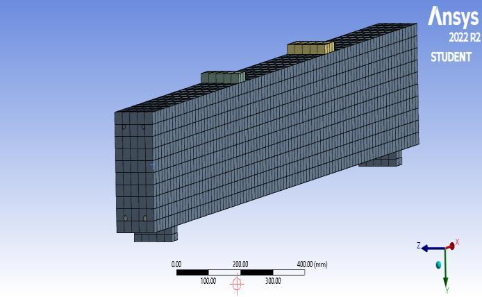
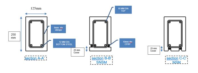
Five Under-reinforced concrete beams (125 × 250 ) are preparedandoneofthemisstrengthenedbyinsertingSNSM CFRPstripsrectangularincrosssectionandanotheronewith CFRProdcircularincrosssectionatstraightprofiles.They werecreatedconcretecoversof25mmforSNSMand12mm for NSM. The comparative flexural response of beams was evaluated by applying four-point loading to the present beams. Strains and mid-span deflection of the beam is measuredusing(ANSYSFEMsoftware).Thissoftwarewas chosenbecauseofitsprecisionwhenitcomestomodeling strengthenedRCbeams ThedimensionsofRCbeamswere asfollows:2300mmlong,arectangularcross-sectionof125 mmwideand250mmhigh,withaspanbetweensupportsof 2000 mm. The reinforcement of a 2-12 mm steel bar in tensile and 2 -10 mm in compression is used. In order to avoid shear failure, a transverse reinforcement of 6 mm diameterspacedat50mmwasplacedalongtheRCbeam. ThefiveRCbeamswerereinforcedaccordingtoFig.1,Fig-3
andTab.1,withCFRProds10mmindiameteranda15x5 mmstripofCFRP.
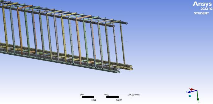
Thetotalnumberofelementsforthereferencebeamis6033 with 26213 nodes. Element size is taken as 25mm for refinementofmatrixmeshtoachieveaccuracyinoutputdata. Thereare740nodesand368elements generatedonlyfor longitudinalsteelreinforcementwhereasthestirrupssteel takes990elementsinmeshing.Thestrengtheninglengthof CFRP isconsideredthroughoutthelengthofthebeam.
02 StrengthenedRCbeamusingtheSNSM techniquewith10mmdiameterCFRProds
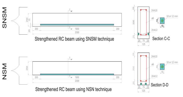
03 StrengthenedRCbeamusingtheSNSM techniquewith5x15mmCFRPstrip
04 StrengthenedRCbeamusingtheNSM techniquewith10mmdiameterCFRProds

05 StrengthenedRCbeamusingtheNSM techniquewith5x15mmCFRPstrip NSM5x15
Material properties:
Theconcretehasbeenmodeledasasolidelementhaving41 MPa as a compressive Ultimate strength and 5 MPa as a Tensile Ultimate strength in ANSYS. Young’s modules of concreteisconsideredtobe32GPa,whereasthePoisson’s Ratio is take as 0.18. In order to model the tension steel reinforcementmaterialusedasaHYSDsteelhavingdensity 7850Kg/m3modulusofelasticity200GPa,Poisson’sratio

0.3,tensileyieldstrengthof550MPaAndcompressiveyield strengthof250MPa.Thestirrup steelhaving300MPaasa tensileyieldstrength. CFRPhas anelasticmodulus of290 GPa,andatensilestrengthof3100MPa.
ANALYTICAL STUDY
Macaulay's Method,alsoknownasthedoubleintegration method,isamathematicaltechniqueusedtodeterminethe equationthatdescribesthedeflectedshapeofabeam.This method simplifies the process of finding the equation for beamdeflectionbyenablingtheuseofasingleequationfor bendingmomentthroughoutthelengthofthebeam.

Before Macaulay's paper in 1919, the equation for beam deflection could not be expressed in closed form, and different equations for bending moment were used in different regions of the beam. Macaulay's Method revolutionizedthisapproachbyprovidingaunifiedequation forbendingmomentalongtheentirelengthofthebeam.

By applying Macaulay's Method in conjunction with the Euler-Bernoullitheory,theexpressionforbendingmoment canbeintegratedtoobtaintheequationfordeflection.This integration process considers the properties of the beam, such as the flexural rigidity (EI), assuming it remains constant(i.e.,thebeamisprismatic).
Ifweassumetheflexuralmembertobeprismatic,thenEIis constantandwecansolvethegeneraldeflectionequationas follows:
principal stresses:
The value of maximum principal stress,also knownas the majorprincipalstress,occurswhentheshearstressactingon one of the principal planes is zero. For biaxial (2D) stress conditions, thereare two principal stresses:the maximum principalstressandtheminimumprincipalstress.
The equation for the maximum principal stress, σ₁, canbe expressedasfollows:

Where,
P=Loadapplied
δL=Changeinlength
A=Cross-sectionalarea
σ=Axialstress
L=Lengthofthecomponent
V=Volumeofcomponent
E=Youngsmodulus
Where:
σx andσyarethenormalstressesinthexandydirections, respectively.τxyistheshearstressactingonthexyplane. Thisequationallowsyoutocalculatethemaximumprincipal stress when you know the normal stresses in the x and y directionsandtheshearstressonthexyplane.
The principal stresses represent the maximum and minimumvaluesofnormalstressesactingontheprincipal planes.Theyplayacrucialroleinanalyzingthestressstate ofamaterialandunderstandingitsfailurebehaviorunder differentloadingconditions.
Strain energy
Strainenergyreferstothepotentialenergythatisabsorbed by a body as a result of deformation or strain. It is representedbythesymbol"U".Thestrainenergyabsorbed byamaterialisequivalenttotheworkrequiredtodeformor straintheobject.Thisrelationshipallowsustoexpressthe strainenergyasthedeformationwork.
Mathematically,wecanstate:
Strain energy = Deformation work
Inthecaseofamemberwithaconstantcross-sectionanda graduallyappliedload,thestrainenergycanbecalculatedas the area under the load-extension curve. This area represents the work done or the energy absorbed by the materialduringthedeformationprocess.
The specific equation for calculating the strain energy in such cases depends on the nature of the load and the materialbehavior.Forlinearlyelasticmaterials,thestrain energycanbecalculatedusingtheequation: U=½xPxδL or
Forpurebendingmomentoverthecomponentwiththe constantcross-sectionalarea,thestrainenergyisgivenby,
Where,
M=Bendingmoment
L=Lengthofcomponent
E=Modulusofelasticity
I=Momentofinertia
3. RESULTS AND DISCUSSIONS
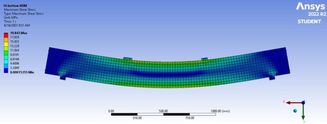
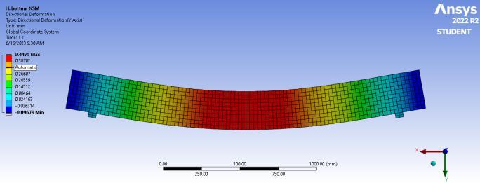
Theresultofnumericalstudyisillustratedinfig6-10which showstheforce-maximumdeflection,maximumshearstress, equivalentelasticstrain,StrainEnergyandEquivalentStress

Fromtheaboveloaddeflectionchart,itisnoticethat the SNSM-10techniqueresultedina27%reductionindeflection, whiletheNSM-10techniqueachievedan85%reduction.This indicatesthatbothmethodseffectivelyincreasethebending capacityoftheRCbeams.
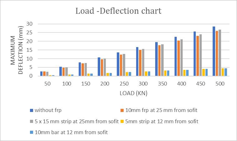
Thehigherresistancetomid-spandeflectionobservedin theNSMmethodisattributedtotheincreaseintheinternal leverarmofthetensilematerialinthereinforcedsection.The internalleverarmreferstothedistancebetweenthecentroid ofthetensilereinforcementandtheneutralaxisofthebeam. Byplacingthereinforcementclosertotheneutralaxis,the NSMtechniqueincreasestheleverarm,resultinginenhanced bendingcapacityandreduceddeflection.

Theimpactofthestrengtheningrebar'scross-sectionon the deflection criteria is noted to be insignificant. This is because the same amount of tensile reinforcement area is applied for strengthening regardless of the cross-sectional shapeoftherebar.Theprimaryfactorinfluencingdeflection reduction is the change in lever arm resulting from the locationofthestrengtheningreinforcement.

-2:ComparisonofMaximumShearStress
It is observed that the SNSM technique results in a significantincreaseinshearstress,witha20%increasefor SNSM-10anda25%increaseforSNSM-5x15.Ontheother hand,theNSMmethodshowsa reductionof67%inshear stressforbothNSM-10andNSM-5x15.
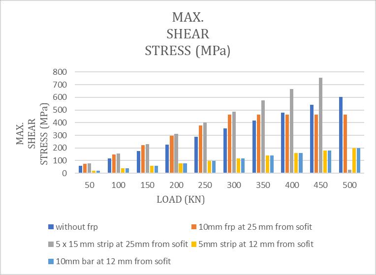
The cross-sectional shape of the strengthening reinforcementhasanotableimpactontheshearcapacityof the RC beam strengthened with the SNSM technique. The specific cross-sectional shape, such as the dimensions and configuration of the reinforcement, influences the shear resistanceofthestrengthenedbeam.
In the case of the SNSM technique, where the strengtheningreinforcementisplacedonthelateralsidesof thebeam,thegeometryanddistributionofthereinforcement play a significant role in enhancing the shear capacity. By increasing the cross-sectional area and optimizing the arrangementofthestrengtheningreinforcement,theSNSM technique effectively increases the shear resistance of the beam.
However, in the NSM method, where the strengthening reinforcementisplacedonthebottomsurfaceofthebeam, the reduction of 67% in shear stress indicates that this
method does not significantly contribute to the shear resistance capacity of the RC beam. The NSM technique primarily focuses on enhancing the flexural capacity and reducing deflection, but its impact on shear resistance is limited.
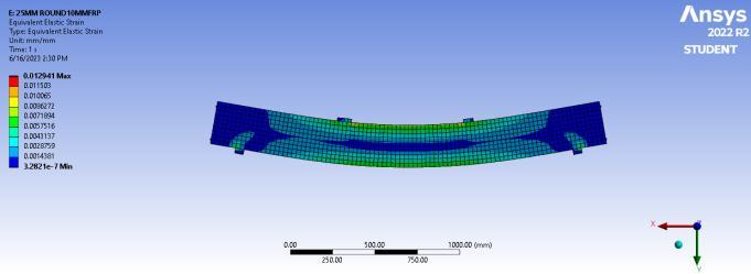
A significant decrease in equivalent strain in reinforced concrete (RC) beams through the use of strengthening techniques, particularly the side near surface mounted (SNSM)andnearsurfacemounted(NSM)methods.
Chart-3indicatesa20%decreaseinequivalentstrainfor SNSM-10andSNSM5X15comparedtothereference(REF) case.Additionally, there isan 86.5% decrease instrain for NSM-10andNSM-5x15.
IntheNSMmethod,thestrengtheningreinforcementis placed at the critical tensile location in the RC beam. This strategic placement significantly improves the tensile strengthinflexureofthebeamcomparedtotheSNSMand REFcases.Byintroducingadditionaltensilereinforcementin thecriticallocations,theNSMmethodeffectivelyreducesthe equivalentstrainandenhancesthestructuralperformanceof theRCbeamunderflexuralloads.
The decrease in equivalent strain reflects the improved resistance of the strengthened beams to deformation and indicates a more robust and stable structural response. Lowerstrainvaluessuggestreducedmaterialelongationand improvedloaddistribution,resultinginenhancedstructural integrityandperformance.

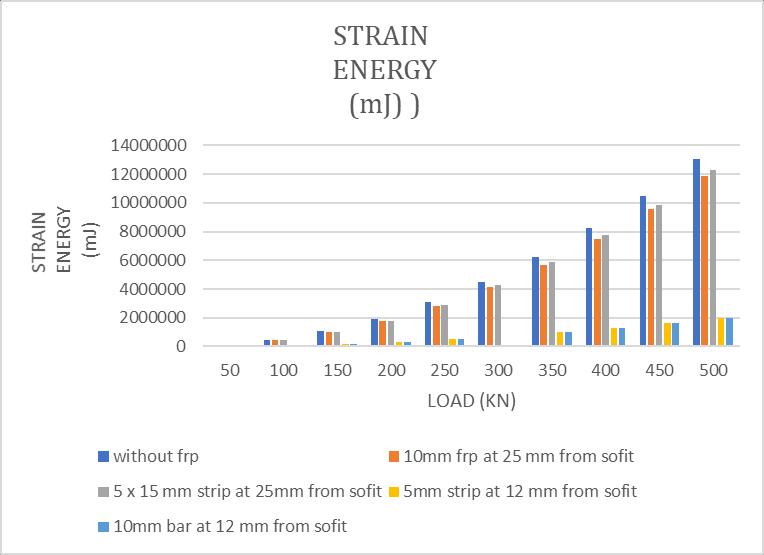
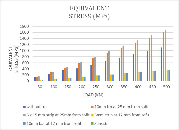
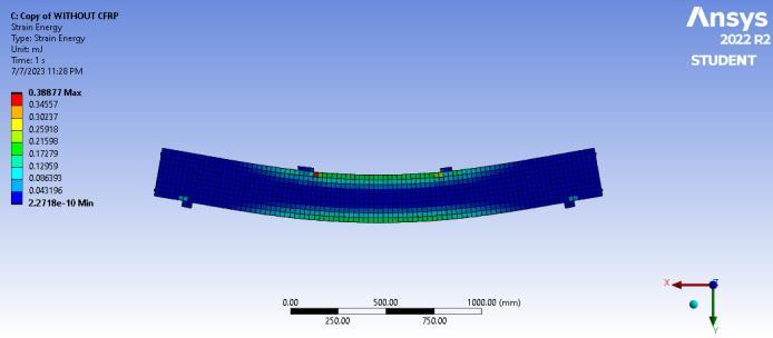
Chart-4indicatesanexponentialincreaseinstrainenergy.It showsadecreaseof7%to8%instrainenergyforSNSM-10 andSNSM-5x15cases,whileasignificantreductionof83%to 85%isobservedforNSM-10andNSM-5x15.
The decrease in strain energy in the SNSM-10 and SNSM5x15casescanbeattributedtothedecreaseinductilityofthe RC beam strengthened with CFRP reinforcement. The introductionofCFRPreinforcement increasesthestiffness andstrengthofthebeam,resultinginreducedductility.Asa result, less strain energy is absorbed by the beam during deformation.
Ontheotherhand,thesignificantreductioninstrainenergy observed in the NSM-10 and NSM-5x15 cases can be attributed to the decrease in internal shear force. The presenceofCFRPreinforcementintheNSMmethodreduces shear deformation in the beam, resulting in a decrease in strainenergy.
Itisimportanttonotethatstrainenergyisameasureofthe energyabsorbedbythestructureduringdeformation.The decreaseinstrainenergysuggeststhatthestrengthenedRC beamexhibitsamoreefficientandstifferresponse,withless energydissipatedandabsorbedbythestructure.

Theequivalentstressofthereinforcedconcrete(RC)beamis observed to increase by 43% for SNSM-10 and 52% for SNSM-5x15. This suggests a significant effect of the crosssectionalareaofCFRPstrengtheningontheequivalentstress.
TheincreaseinequivalentstressintheSNSM-10andSNSM5x15casescanbeattributedtotheadditionalreinforcement providedbytheCFRPstrengthening.ByincreasingthecrosssectionalareaoftheCFRPreinforcement,thebeam'scapacity to resist external loads is enhanced, resulting in higher equivalentstress.
In contrast, the NSM technique exhibits a highly reduced ductility, leading to a decrease in equivalent stress. The decreasedductilityintheNSMtechniquecausesareduction of67.3%comparedtothereference(REF)caseand77.4% comparedtotheSNSMcases.
Itisimportanttonotethattheeffectofthecross-sectional areaofCFRPreinforcementontheequivalentstressinthe NSMtechniqueisreportedtobeinsignificant.Thissuggests that, in the NSM technique, other factors such as the placementofthereinforcementincritical tensilelocations play a more dominant role in determining the equivalent stress.
The equivalent stress is a measure of the stress level experienced by the material and is an important consideration in assessing the structural behavior and performance. The changes in equivalent stress observed indicatetheimpactofstrengtheningtechniquesonthestress distributionandload-carryingcapacityoftheRCbeam.

3. CONCLUSIONS
Strengthening Effect: Both methods effectively enhancethestrengthandperformanceofreinforced concrete(RC)elements.TheNSMmethodfocuseson improvingflexuralstrengthandreducingdeflection, while the SNSM method emphasizes flexural and shearcapacityenhancements.
Flexural Strength: The NSM method demonstrates higher resistancetomid-spandeflection due to an increase in the internal lever arm of the tensile reinforcement. This leads to a significant improvementintheflexuralstrengthoftheRCbeam.
Shear Capacity: The SNSM method provides increased shear strength due to the strategic placementofthestrengtheningreinforcementonthe lateral sides of the beam. This reinforcement configuration improves shear resistance and contributestoenhancedstructuralperformance.
Ductility: The NSM method exhibits reduced ductility, which can result in a decrease in strain
energy and equivalent stress. This characteristic should be considered when evaluating the overall behavior and performance of the strengthened structure.
Cross-SectionalArea:Thecross-sectionalareaofthe CFRP (Carbon Fiber-Reinforced Polymer) reinforcementintheSNSMmethodhasasignificant impactontheshearcapacityandequivalentstressof the RC beam. Increasing the area can lead to improved performance and increased equivalent stress.
DesignConsiderations:ThechoicebetweentheNSM and SNSM methods depends on the specific structuralrequirements,loadconditions,anddesign considerations of the project. Factors such as materialproperties,structuralconfiguration,andthe presence of critical locations (e.g., shear zones) shouldbecarefullyevaluated.
ACKNOWLEDGEMENT
Firstandforemost,IamdeeplyindebtedtoProf.P.S.Lande for his inspiring guidance, constructive criticism, and unwaveringsupportthroughoutthisjourney.Hisexpertise and insightful suggestions have played a crucial role in shapingthedirectionandqualityofmywork.
IwouldalsoliketoextendmygratitudetotheHeadofthe Department, Prof. Dr. S. K. Hirde, for his valuable inputs, encouragement, and constant support. His leadership and mentorship have been instrumental in creating an environmentconducivetoacademicgrowth.
Iamimmenselygrateful to all thestaffmembers for their valuable suggestions, timely assistance, and unwavering support. Their dedication and willingness to share their knowledgeandexpertisehaveenrichedmyunderstandingof thesubjectmatterandhavesignificantlycontributedtothe successfulcompletionofmypaper.
IwouldalsoliketoexpressmysincerethankstoDr.A.M. Mahalle, Principal of Government College of Engineering, Amravati, for providing the necessary facilities and resources at the right time. His commitment to academic excellenceandcreatingaconducivelearningenvironment hasbeeninvaluable.
Lastly, I would like to extend my appreciation to my classmates, whose encouragement, support, and constant inspiration have played a pivotal role in keeping me motivatedandfocusedonmyresearch.Theircamaraderie and intellectual discussions have enhanced my learning experience.
Iamtrulyfortunatetohavehadtheguidanceandsupportof theseremarkableindividualswhohaveshapedmyacademic journey and contributed significantly to the successful completion of my paper. Their unwavering support and belief in my abilities have been a constant source of inspiration.
Onceagain,myheartfeltthankstoProf.P.S.Lande,Prof.Dr. S.K.Hirde,thestaffmembers,andDr.A.M.Mahallefortheir invaluablecontributions.
REFERENCES
[1] PeterSabola,*,SergejPriganca,“ShearStrengtheningof Concrete Members Using NSM Method”, Procedia Engineering65(2013)364–369
[2] J.A.O.Barros*,S.J.E.Dias,“NearsurfacemountedCFRP laminatesforshearstrengtheningofconcretebeams”, Cement&ConcreteComposites28(2006)276–292
[3] LauraDeLorenzis,“AnchorageLengthofNear-Surface MountedFiber-ReinforcedPolymerRodsforConcrete Strengthening AnalyticalModeling”,StructuralJournal vol.101-3,pg375-386.
[4] BoulebdAdel,FerhouneNoureddineetal[],“Modelingof CFRPstrengthenedRCbeamsusingtheSNSMtechnique, proposedasanalternativetoNSMandEBRtechniques” A.Boulebdetalii,Frattura edIntegritàStrutturale,54 (2020)21-35;DOI:10.3221/IGF-ESIS.54.02
[5] FirasAl-Mahmouda,*,ArnaudCastelb,RaoulFrançois b,ChristianTourneur,“StrengtheningofRCmembers with near-surface mounted CFRP rods” , Composite Structures91(2009)138–147.
[6] AntonioBilotta,FrancescaCeroni,EmidioNigro,Marisa Pecce,“EfficiencyofCFRPNSMstripsandEBRplatesfor flexuralstrengtheningofRCbeamsandloadingpattern influence”, Composite Structures (2014), doi: http://dx.doi.org/10.1016/j.compstruct.2014.12.046
[7] Sharaky, I.A., Torres, L., Comas, J., Barris, C. (2014). Flexural response of reinforced concrete (RC) beams strengthened with near surface mounted (NSM) fibre reinforcedpolymer(FRP)bars,Compos.
[8] Struct., 109, pp. 8-22, DOI: 10.1016/j.compstruct.2013.10.051

[9] Mohammad Abdallah et al “Experimental study on strengthening of RC beams with Side Near Surface Mountedtechnique-CFRPbars”,CompositeStructures (2019), doi: https://doi.org/10.1016/j.compstruct.2019.111716
[10] Md Akter Hosen, Mohd Zamin Jumaat , A.B.M. Saiful Islam.SideNearSurfaceMounted(SNSM)techniquefor flexuralenhancementofRCbeams.Materials&Design 2015;83:587–597
[11] Mohammad Al-Zu'bi et al.(2021) “The effect of length and inclination of carbon fiber reinforced polymer laminatesonshearcapacityofnear-
[12] Saja Waleed Fathuldeen1a , Musab Aied Qissab (2019)“BehaviorofRCBeamsStrengthenedwithNSM CFRPStripsunderFlexuralRepeatedLoading”Articlein StructuralEngineering&Mechanics
[13] Salam Al-Obaidi et al.[] “Flexural strengthening of reinforcedconcretebeamswithNSM-CFRPbarsusing mechanical interlocking”, Journal of Building Engineering31(2020)101422
[14] Nasih Habeeb Askandar and Mahmood , “Torsional Strengthening of RC Beams with Continuous Spiral Near-Surface Mounted Steel Wire Rope”, Int J Concr StructMater(2020)14:7
[15] MatteoBreveglieria,,AlessandraAprilea,JoaquimA.O. Barros, “Shear strengthening of reinforced concrete beams strengthened using embedded through section steelbars”,M.Breveglierietal./EngineeringStructures 81(2014)76–87.
[16] I.A. Sharakya,b, S.A.I. Selmyc , M.M. El-Attarc , H.E.M. Sallamb,“TheInfluenceofinteractionbetweenNSMand internal reinforcements on the structural behavior of upgrading RC Beams”, , Composite Structures (2019), doi:https://doi.org/10.1016/j.compstruct.2019.111751
[17] LI Xiaoran and Wang Yuanfeng , “Three-dimensional Nonlinear Finite Element Analysis of Reinforced Concrete Structures based on ANSYS Program”, 2010 2ndInternationalConferenceonComputerEngineering andTechnologyV6-43
[18] Jin-GuangYua,LiangChenga,ShuLiub,c,BingFud,e, Bo Li b,, “Inorganic adhesive based near-surfacemountedfibrereinforcedpolymerforstrengtheningof concretestructures:Anoverview”,Structures33(2021) 2099–2120.
[19] ACI440.2R-17.Guideforthedesignandconstructionof externally bonded FRP systems for strengthening concrete structures. Farmington Hills, MI, USA: AmericanConcreteInstitute,2017.
[20] R.M. Firouz, E.B. Pereira, J.A.O. Barros, Cementitious adhesives for NSM carbon laminate strengthening systemwithtreatedsurfaces,IABSESymposium,2019, Guimaraes surface mounted retrofitted reinforced concretebeams”,StructuralConcrete.2021;1–15.
[21] Macaulay,W. H.(1919),‘Note on the deflection of the beams’,MessengerofMathematics,48,pp.129-130.
[22] Gere, J.M and Goodno, B.J. (2008), Mechanics of Materials,7thEdn.,CengageEngineering
[23] Obaidat,Y.T.,Heyden,S.,Dahlblom,O.(2010).FEMstudy ontheeffectofCFRPstiffnessandwidthonretrofitted reinforced concrete beam behaviour, Structural RetrofittingofReinforcedConcreteBeamsUsingCarbon Fibre
[24] Obaidat,Y.T.,Heyden,S.,Dahlblom,O.(2010).Theeffect of CFRP and CFRP/concrete interface models when modelling retrofitted RC beams with FEM, Compos. Struct., 92(6), pp. 1283-1544, DOI:10.1016/j.compstruct.2009.11.008.
[25] Camanho, P., Davila, C.G. (2002). Mixed-Mode Decohesion Finite Elements in for the Simulation CompositeofDelaminationMaterials,Nasa.,37(16),pp. 1415-1438,DOI:10.1177/002199803034505.
[26] Said, H. (2010). Deflection prediction for FRPstrengthenedconcretebeams,J.Compos.Constr.,14(2), pp.244-248,
[27] ACI 440.2R-08. (2008). Guide for the design and construction of externally bonded FRP systems for strengtheningexistingstructures.
[28] Boukhezar, M., Samai, M.L., Mesbah, H.A., Houari, H. (2013).Flexural behaviourofreinforcedlow-strength concretebeamsstrengthenedwithCFRPplates,Struct. Eng. Mech., 47(6), pp. 819-838, DOI: 10.12989/sem.2013.47.6.819.
[29] Shukri, A.A., Hosen, M.A., Muhamad, R., Jumaat, M.Z. (2016). Behaviour of precracked RC beams strengthened using the side-NSM technique, Constr. Build. Mater., 123(1), pp. 617-626, DOI: 10.1016/j.conbuildmat.2016.07.066.
[30] Stoner, J.G. (2015). Finite Element Modelling of GFRP ReinforcedConcreteBeams,Master'sThesis,University ofwaterloo,Waterloo,Canada.

