Portable Small-Scale Vertical Axis Wind Turbine with Pitch Angle Control System (H-Type VAWT)
1Doctor, Department of Mechanical Engineering, Canadian International College (CIC), Cairo, Egypt
2,3,4,5,6Students, Department of Mechanical Engineering, Canadian International College (CIC), Cairo, Egypt ***
Abstract - This Research paper aims to document the process of designing & manufacturing a proof of concept of a portable vertical axis wind turbine with A novel control method is also demonstrated to offer exciting possibilities for improving existing VAWTs. The idea behind the portable design is for the user to be able to take the wind turbine to remote places that lack electrical energy for long periods of time like refugee camps & military barracks, the reason for using the pitch angle control system is that by varying the pitch angle of the blade this generates more lift force on it which corresponds to a higher level of energy absorption and output power
Key Words: Lift force, Portable, Vertical Axis, Wind turbine, Darrieus vertical axis wind turbine (H-type VAWT), Computational fluid dynamics (CFD), Variable pitch angle control, Control, pitch angle.
1. INTRODUCTION
Energy resources can be divided into two types nonrenewable(oil,coal,andnaturalgas)andrenewable(wind, solar,geothermal,andhydropower)[1].Asnon-renewable energyresourcesarebecomingscarceandexpectedtorun out shortly [2], therefore it is a fact that ways to obtain energy from renewable resources must be developed to satisfythecurrentandfutureneedsofpowerconsumption. Inthischapter;thetypesofnon-renewableandrenewable energy will be discussed to understand the importance of usingrenewableenergy
1.1 Non-Renewable Energy
Fossil fuels are generated from the preserved remains of plants and animals and are found underground, as their collectivenamesuggests.Fossilfuelsincludecoal,petroleum, naturalgas,oilshale,bitumens,tarsands,andheavyoils.All ofthemcontaincarbonandareformedduetothegeologic processthatactsontheremainsoforganicmatterandthis processtakes300to400millionyearstoformnaturally[3]
AllfossilfuelscanbeburnedintheairtoproduceThermal energy;thisenergycanthenbeuseddirectlylikeinhome furnaces or can be used to heat water which in turn produces steam which drives a turbine to generate electricity, this process is called geothermal power generation[4].
The applications mentioned are essential for a lot of industries.However,fossilfuelcombustiondoesmoreharm than good due to the large amounts of harmful emissions suchasCO2,Greenhousegases&particulateMatterwhich consequentlyaffectsnotonlytheenvironmentbutalsothe General well-being of the population [5]. According to the Intergovernmental Panel on Climate Change (IPCC)in2018,it wascalculatedthat89%ofglobalCO2Emissionscamefrom fossilfuelcombustionandthatfossilfuelusageistheroot causeofglobalwarming[6,7]
ClientEarthandIPCCwarnthatfossilfuelconsumptionmust behalvedinthenext11yearstoavoidexceedingaglobal temperature rise of 1.5°C, which would cause severe consequences such as increased sea levels, extinction to certainspeciesofanimalsandcrops,andextremeweather [6, 7]. However, a report published by the United Nations Climate Change revealsthatcurrenteffortsareinsufficientto preventtemperaturesfromrisingabove1.5°Cbytheendof 2030, and the world may be on track for around 2.5°C of warmingbytheendofthecentury.Luckilyinthe1980s,the familiarsustainableformsofenergywerepresented(solar& wind)[8]
Thisnewapproachtorenewableenergygenerationiscrucial foroursurvivalandasthe International Renewable Energy Agency (IRENA)Director-General Francesco La Camera said “Wearestaringintoaterrifyingabyssofirreversibleclimate consequencesifwefailtoact,”[9].

Moreover,Crudeoilreservesaredepletingatarateofmore than 4 billion tons a year and at this rate, our known oil reservescouldrunoutinjustover53years.Ifweincrease gasproductiontofilltheenergygapleftbyoil,ourknown gas reserves will also be used up within 52 years. And if people try to accommodate for the decrease in the productionofoilandnaturalgasbycoal,theknownreserves willbeemptyafternearly150years[2].
1.2 Renewable Energy
Renewableenergyresourcesarethesourcesthatnaturally renewthemselvesataratethatmakesthemseeminfinite. Therearemanytypesofrenewablesourcesofenergysuch as(solar,wind,hydro,tidal,geothermal,andbiomass)[10]
2.0 Mechanical Design

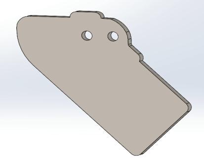
When determining the overall dimension of the project, variousfactorswerecarefullyconsideredtoensurethebest outcome. One of the most important considerations was portability,asitneededtobeeasilytransportedfromone locationtoanother.Additionally,theproductwasdesigned to cater to smaller-scale operations, making it more accessibletoawiderrangeofusers.User-friendlinesswas alsoakeyconsideration,asthegoalwastocreateaproduct that was easy to use and navigate, even for those with limitedtechnicalknowledge.Allthesefactorswerecarefully weighedandbalancedtocreateafinalproductthatwasboth functionalanduser-friendly.

The portable wind turbine can be divided into two main partsupper,andlowerlimps.Upperlimpsarethelinks,four bar mechanism, servos, and blades. Lower limps are the electronichousing,legs,andbasewhichconnectsthelower andupperparts.
2 1 Upper body of turbine
Thebladeshaveanairfoil NACA0018profilewitha chord length of 190mm. Blades change their bitch angle using a servomotorcontrolledbyamicrocontroller.Furthermore, thelinksthatholdtheblades,aredesignedtocontractand extend using a four-bar mechanism. Designing such mechanism needed to have a smooth transformation between the mentioned two states which encouraged the ideaofusingthefour-barmechanismwithgearsasshownin figure1.However,aComplexmechanismdictateshavinga partwithcomplexgeometryasacomplementary.Themost complexpiecegeometricallyistheservos’holders,working as an intermediate part between the servo and the blade showninfigure2
2.2 Lower body of turbine

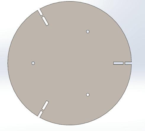
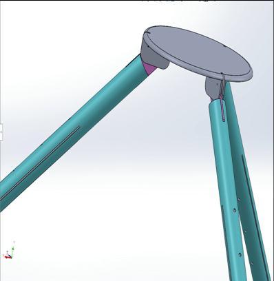
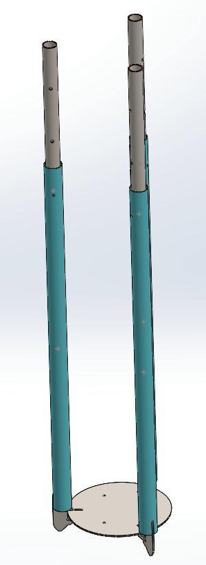
The tripod acts as the base of the portable wind turbine, providing the necessary support and stability. The main objectiveofthedesignwastocreateamechanicallyrobust structurethatcouldwithstandthedynamicforcesexertedby thewindturbine.Theplacementofthelegsata45-degree anglefromthebaseprovidedastableandstableplatform, reducingtheriskofslippageorexcessivevibrationduring workThisarrangementtheseconsiderationsarenecessary tomaintainthedesignintegrityofthewindturbineunder different wind conditions. First, the initial design of the tripodfeaturedthreelegspositionedata 45-degreeangle fromthebase,ensuringstabilityandrigidityagainstexternal forces. The tripod comprises three main parts: the base, fixation plate, and legs, as depicted in Figures 3, 4, and 5, respectively.
Thebaseistheintermediatepartbetweenrotatinglinksand thelegs.TheFixationplateisusedtoconnectbaseandlegs. Finally,thelegsareusedtostabilizethewindturbineusing frictionproducedbetweenlegsendsandground.Infigure4, thetripodisabletoshrinkinsizeviamovinglegstowards thecenter-closing-bypivotingaroundthefixationpointin the fixation plate. Furthermore, the legs are able to be extendedincaseofthegroundisnotflatorhadlowfriction coefficient.
3.0 Stress analysis

A stress analysis was conducted on the lower parts of the windturbineshowninthefigure8.Thestressanalysiswas doneusinga100kgusingSolidWorks2020.Resultsofthis simulationwasconclusivethatthegeometryandmaterial selectionofAluminumwasadequateandmorethanenough. Putting these findings as followed allows to draw a conclusionthattheTri-podissafeforcommercialuse.


Tipspeedratio(TSR) ,asignificantcharacteristicrelated toVAWTblades,iscalculatedwithusingthefollowingthe equation,

Theforcesactingoneachbladecanbeusedtopredictthe actualVAWTperformance.Figure28depictstheVectorsof velocity and force acting on Darrieus turbine blades. The tangentialvelocityvectoroftherotorisrepresentedbythe velocity . The relative velocity is represented by the resultant velocity vector . which is composed of the induced velocity (U) and blade velocity (V) vectors. The angleofattack istypicallydefinedastheangleformed bytherelativevelocitydirection,W,andthechordlineofthe
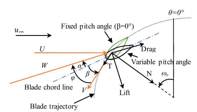
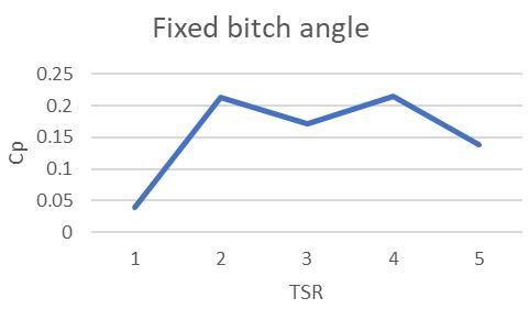
blade.ThepitchangleofthebladeisasspecifiedinRef.[13] where istheangleformedbythedirections and .The angleofattack andrelativewindspeed(W),whichisa function of the azimuth angle ( ), obviously continuously change during each cycle. As a result, the magnitude and orientation of both the lift and drag forces vary with the azimuthalpositionoftheblade.Themainforcesactingon VAWTbladesarealsodepictedinFigure28lift,drag,normal (N),andtangential(T).Thetangentialforce(T)[13]canbe usedtoestimaterotorperformance.Thepowercoefficient (Cp)istheratioofmechanicalpowergeneratedbythewind turbine(Pm)towindpoweravailable(PW)[14]
FEATURE
ROTOR RADIUS (R) [MM]
656
1000
BLADE PROFILE [-] NACA 0018
CHORD © [MM] 190
PITCH ANGLE (Β) [°] -6,-4,-0,4,6

AZIMUTH ANGLE (Θ) [°] 0 to 360
TIP SPEED RATIO (Λ OR TSR) [-] 1, 1.7, 2, 2.7, 3.3

5.3 Ansys Pre-process
where istheairdensity(1.225kg/m3),andAisthearea swept by the turbine (e.g., for the H-type Darrieus wind turbine,A=2RH,whereHisthebladelength).However,for VAWTs at low TSRs, a negative torque is often generated becauseofthelargedynamiccyclicvariationsintheangleof attack(α).
5.0 COMPUTATIONAL FLUID DYNAMICS (CFD)
5.1 Introduction
Studyingthecharacteristicsofwindturbineswasexpensive duetotheuseof windtunnels.Theriseofmorepowerful computers had given researchers a new tool to study the behaviorofalmostanysystemwhenincontactwithdynamic fluid loads. Inexpensive and comprehensive as it is, this methodwasfavorabletobeusedforagraduationproject. Thegoalofstudyingwindturbinebehavioristodetermine best way of increasing performance by using a control systemforpitchangleofeachblade.
5.2 The CFD model
Ansysfluentwasusedbecauseithasintuitiveinterfaceand freelicenseforstudents.Simulationwasa2-Dthree-bladed H-Darrieus VAWT with NACA 0018 airfoil at different tip speed ratios for both fixed and variable pitch angle configurations.Slidingmeshtechniquewasappropriateas thedesiredmeasuredoutputswerevariableintimewhich requiredtheuseofatransientsimulation.
CFD simulations with Ansys are not magically done. First uploadtherequiredgeometry.Secondapplyagoodmeshon top of it. Third tune the parameters of the simulation. All explainedinthefollowingsection.

A. Geometry:
Thegeometryisdividedintomultipledomainsasfollow:
1. Stationary domain: The dimensions need to large enough to prevent a solid blockage effect of the lateralboundariesTherefore,thedimensionsofthe domainare40rotordiametersupstream(L1),100 rotor diameters downstream (L2), and 60 rotor diameterswidth(W)[11].
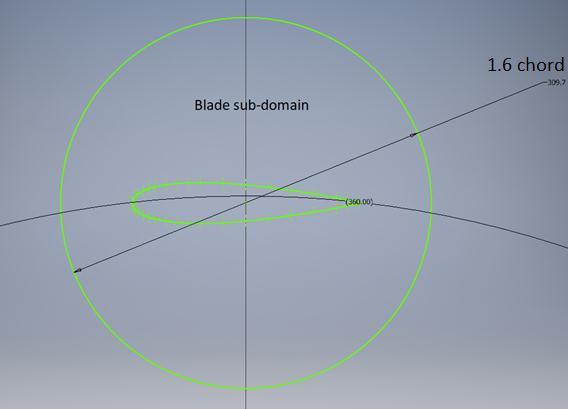
3. Bladesub-domain:Additionalcircularsubdomains areaddedtohaveafinermesharoundtheairfoils. Airfoils are hard to study because of its fast and highly changeable pressure around it with every step.Theradiusofthedomainwasapproximately 1.6thelengthofblades’chord.
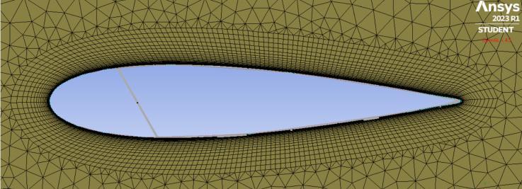
The solver is quite capable at capturing the pressure and sheerstressinelementswhenit’sintheviscoussublayeror fullyturbulentsublayer.concludingtohaveelementsclose to the wall to have Y+ close or under one [11] to ensure accurate results. The blade was set to have 525 nodes on edge and an inflation for 30 layers with first element thicknessof1e-5ensuringaY+under1.

Generating mesh is relatively hard process as it decides complexity degree of solving the simulation. Although a complex simulation to solve is desired for its accurate results,thedownsideistheneedofbettertechnologyand patience, which means more money, to solve these hard problems.Thecoreproblemisnowclear,whengenerating mesh,engineersshouldbalancebetweenaccuracyandcost.
According to the literature [11}, the biggest two factors affecting this kind of CFD is the value of Y+ and CourantFriedrichs-Lewynumber(cfl)withinadistanceof10mmfar from the blades and at the interface of rotating zone. The elementsizeontheinterfaceofrotatingzonehasbeensetto 39mm.

ANSYS-Fluent uses many turbulence models based on Reynolds-averaged Naiver–Stokes (RANS) equations to representtheturbulentpropertiesoftheflow.Thesemodels typicallyincludetwoadditionaltransportequationsthatare solved for the turbulence kinetic energy (k) and its dissipationrate(εorω).TheShear-StressTransport(SSTkw) model has been used when the literature was revised [11].

6.0 Control:
Infixedanglesliftiscreatedbyonly1or2bladesthatare meeting the wind flow at a better angle then slowed by a breakingturbulencegeneratedfromthe remainingblades meetingtheairataworseangle.So,thismakesotherblades suffer from mixed-up (vortex) air causing limited output fromavailablewindenergy.
Therefore,variablepitchsystemshowsliftfrommorethan twobladesandlessdragfromothers.Whichtranslatesintoa higher level of wind energy absorption and output in the formofpowerormechanicaldriveenergysolvingthemain issueofverticalwindturbinesmakingitself-starting.
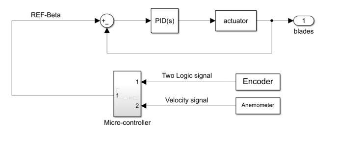
First,TheAnemometerthatisplacedbesideportablewind turbinemeasuresWindspeed(V_W)andpassvaluetothe micro-controller.Then,TheIncrementalEncodermounted ontherotorshaftsendslogicalsignalstomicro-controller for determining position and rotational velocity of rotor shaft.Themicro-controllerusespreviousmentionedvalues tocalculateTipspeedratio(TSR).Selectthebestpitchangel (��)accordingtothebestcoefficientofperformanceC_Pto thecurrentTSRattheendofthecycleeachservomotorattachedtoeachblade-willreceivethesuitablepitchangel in respect of the blade’s position –Azimuth angel (��). A simpleschematicfigure33representswhatwasmentioned up-closetofurtherclarification.
7.0 Cost Analysis
This analysis was carried out according to the Egyptian pricesinJune2023.
As startup company manufacturing 25 wind turbine per month:
one-time fixed cost ( ):
Machines cost=(2x3dprinter)+(1xlasermetalcutting machine) + (1 x laser wood cutting machine) + (1 x arc welding) = (2 x 20,000) + (1x15,000) + (1x120,000) + (1x5,000)=160,000EGP
Fixed cost per month ( ):
Employee’s cost: (2workersx3,000)+(1Maintenanceworkerx3,500)+(2 engineers x 8,000) + (10,000 renting cost) = 35,500 EGP/month.
Power consumption of the facility per month:
Electricity cost: (1000 Kwh/month) x (1.45 EGP/Kwh) = 1,450EGP/month
Total fixed cost per month ( ) = (35,500)+(1,450)= 36,950EGP
Variable cost:
Variable Cost per unit (v):
Materialusedforonewindturbine:
MDFwood(50)+BalsaWood(1,100)+beechwood(100)+ bearings (240) + bolts and nuts (200) + Abs filaments (5,000)+aluminumLinks3kg(1,500)+aluminumsheets
1kg(500)+aluminumpipes8kg(5,000)+aluminumshaft 2kg(1,000)=14,690EGP
ElectronicsComponents: servomotorsx3(1,500)+wires(100)+Alternator(17,000) +2batteries(1,500)+slipring(800)+ArduinoUNO(760)+ inverter(1,000)+Bluetoothmodulex2(400)+breadboards (50) + regulator (300) + anemometer (1,200) + encoder (750)=25360EGP
Variable Cost per unit (v) =14,690+25360=40,050EGP According to the revenue per unit (r) is 46,000 EGP therefore:
Profit per unit = revenue per unit – variable cost per unit= 46,000–40,050=5950EGP
8.0 CONCLUSION
In conclusion, the findings from the real-time Internet of Things (IoT) data and MATLAB analysis provide valuable insightsintotheimpactofbladepitchingontheperformance ofwind turbines.The resultsdemonstratethat employing positive pitch angles can significantly enhance the power coefficientatlowTip-SpeedRatio(TSR)of1,resultinginan approximate4%increaseinCp.
Bycomparingthepowercoefficientvalues,whichincreased from 0.03815712 to 0.041201, it is evident that the blade pitching approach has a positive effect on the turbine's performance. This improvement indicates that the wind turbine'sself-startingcapabilitiescanbeenhanced,allowing

ittoreachitsnominaloperatingspeedwithouttheneedfor additionalpower.
Thesefindingshaveimportantimplicationsforthefieldof windenergy,astheysuggestthatoptimizingbladepitching can contribute to more efficient and cost-effective wind turbineoperations.Byutilizingthebladepitchingapproach, windturbinesystemscanharnessahigherproportionofthe available wind energy, maximizing power generation potential.
REFERENCES:
1. Energy.gov. Energy Sources.2022;Availablefrom: https://www.energy.gov/energysources#:~:text=Primary%20energy%20sources% 20take%20many,%2C%20solar%2C%20geotherma l%20and%20hydropower.
2. Kalair, A., et al., Role of energy storage systems in energy transition from fossil fuels to renewables. EnergyStorage,2021. 3(1):p.e135.
3. kopp, O.C., Fossil Fuel. Encyclopedia Britannica, 2022,December16.
4. Curley,R., Fossil fuels.2011:BritannicaEducational Publishing.
5. Osman,A.I.,etal., Cost, environmental impact, and resilience of renewable energy under a changing climate: a review. EnvironmentalChemistryLetters, 2022.

6. Client Earth. Fossil fuels and climate change: the facts. 2022, February 18; Available from: https://www.clientearth.org/latest/latestupdates/stories/fossil-fuels-and-climate-changethefacts/#:~:text=When%20fossil%20fuels%20are%2 0burned,temperature%20has%20increased%20by %201C.
7. Masson-Delmotte,V.,etal., Global Warming of 1.5° C: IPCC Special Report on Impacts of Global Warming of 1.5° C above Pre-industrial Levels in Context of Strengthening Response to Climate Change, Sustainable Development, and Efforts to Eradicate Poverty.2022:CambridgeUniversityPress.
8. United Nations Climate Change. Climate Plans Remain Insufficient: More Ambitious Action Needed Now. 2022, October 26; Available from: https://unfccc.int/news/climate-plans-remaininsufficient-more-ambitious-action-needednow?utm_campaign=The%20Batch&utm_medium= email&_hsmi=232282177&_hsenc=p2ANqtz zkt5jX6GQ5lao_HMrt4K3FIwCpj2O1mPerybWR1cX
Z8zlRHc7ot8kVX8Q7EiJv17f6M4e7MnXetnDsyKYVjdJYBwA5RgbvI2TlbxRDY27NfIgQ&utm_content=232281151&utm_so urce=hs_email
9. InternationaRenewableEnergyAgency. We face an abyss of irreversible climate consequences, says IRENA DG. 2022, October 27; Available from: https://www.irena.org/News/pressreleases/2022/ Oct/We-face-abyss-of-irreversible-climateconsequences-says-IRENADG#:~:text=%E2%80%9CWe%20are%20staring% 20into%20a,Director%2DGeneral%20Francesco%2 0La%20Camera.
10. Johns Hopkins. Renewable Energy vs Sustainable Energy: What’s the Difference? 2021, July 2; Available from: https://energy.sais.jhu.edu/articles/renewableenergy-vs-sustainable-energy/
11. Kumar,R.,K.Raahemifar,andA.S.Fung,Acritical review of vertical axis wind turbines for urban applications. Renewable and Sustainable Energy Reviews,2018.89:p.281-291.
12. Abdalrahman, G., W. Melek, and F.-S. Lien, Pitch angle control for a small-scale Darrieus vertical axis wind turbine with straight blades (H-Type VAWT). Renewableenergy,2017. 114:p.1353-1362.
13. Dyachuk,E.,etal., Measurements of the aerodynamic normal forces on a 12-kW straight-bladed vertical axis wind turbine. Energies, 2015. 8(8): p. 84828496.
14. Gosselin,R.,G.Dumas,andM.Boudreau, Parametric study of H-Darrieus vertical-axis turbines using CFD simulations. JournalofRenewableandSustainable Energy,2016. 8(5):p.053301.
