SEISMIC ANALYSIS AND RETROFITTING USING STEEL BRACING IN A MULTI-STOREYED BUILDING
Ameena Muhammed A1, Ifthana M N2, Minnu Kurian3 ,Shilpa Sajil4 ,Merin Mathew51UG Student, Dept. of civil engineering, Mar Athanasius College of Engineering, Kothamangalam, Kerala-686666

2UG Student, Dept. of civil engineering, Mar Athanasius College of Engineering, Kothamangalam, Kerala-686666
3UG Student, Dept. of civil engineering, Mar Athanasius College of Engineering, Kothamangalam, Kerala-686666
4UG Student, Dept. of civil engineering, Mar Athanasius College of Engineering, Kothamangalam, Kerala-6866662
5 Assistant professor, Dept of civil engineering, Mar Athanasius College of Engineering, Kothamangalam, Kerala686666 ***
Abstract - In today’s scenario of rapid population increase and the unvarying land mass available, multistoreyed buildings have become inevitable. The structures are more vulnerable to earthquake loads and wind loads as the height of the building increases which will produce lateral displacements and thus accumulates deformations in various members of the building i.e., beams, columns, etc resulting in storey drift. These parameter values may exceed the permissible limits or can even lead to failure of the building. Seismic Retrofitting is the modification of an existing structure to make it more resistant to damages caused to the building due to various earthquake loads. India is divided into four seismic zones i.e., zones II, III, IV and V based on historical seismic activity by the Bureau of Indian Standards among which zone III and IV are considered. Steel Bracings are one of the efficient ways to help the building be seismic resistant. A G+12 storey building is to be analysed using E TABS 2019 software for seismic zones III and IV. The building is analysed against the seismic loads for models that are unbraced, with X bracing, V bracing, Inverted V bracing, K bracing and diagonal bracing at middle and corner configurations. The main parameters to be compared are lateral displacement, storey drift and base shear and the most suitable bracing at both middle and corner configuration among them for both zones III and IV are identified.
Key Words: Earthquake, Seismic Analysis, Steel Bracing, Multi-storey Building, ETabs software
1.INTRODUCTION
Seismic analysis comes under structural analysis, and it includes the calculation of the responses of a structure to earthquakes.In regionswhere earthquakesare prevalent, seismic analysis is a part of structural design. For the analysis ETABS 2018 software is used which is incorporated with all the major analysis used to analyse and design the buildings. Seismic retrofitting is a solution for seismic inadequacy. It makes a building safer and
protects from high winds and earthquakes. It is the moderation of an existing structure to make them more immunetoseismictremor.
A G+12 building is assumed to be in seismic zone III and zone IV, and it is analysed for seismic adequacy using ETABS 2018 software and any seismic inadequacy of the building is satisfied by providing steel bracings as the retrofittingsolution.
2. BUILDING SPECIFICATIONS
The building that has been selected for the analysis is a G+12 storey residential building with 2 3 BHK and 2 1 BHKapartments in each floor. The building isassumed to belocatedatMumbaiatawindspeedof44m/sinseismic zoneIIIandlocatedatMumbaiatawindspeedof47m/s in seismic zone IV founded on type II medium soil, The building selected is first drafted in AUTOCAD and then modelled on ETABS 2018 unbraced and after providing various bracing systems. The information used for modellingthebuildingisgiveninTable1.
P3. EQUIVALENT STATIC ANALYSIS OF THE BUILDING


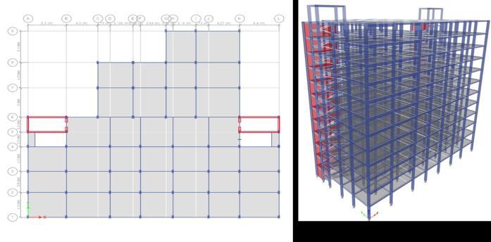
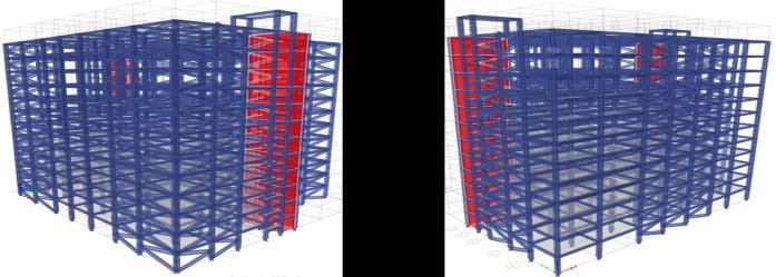
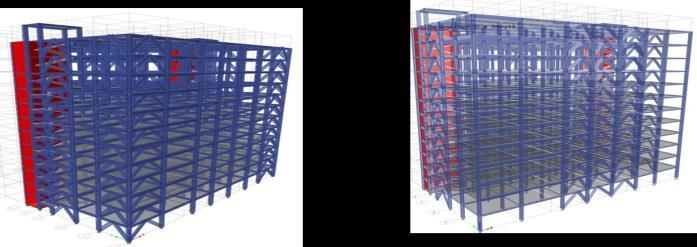
Theanalysisofthebuildingwascarriedoutconsideringall load combinations as specified in IS 456:2000 and IS 1893:2016 using equivalent static analysis for both unbraced as well as braced frames. X, K, V,inverted V and diagonal bracings were provided using the auto select option in ETABS 2018. ISMB 500 Was used for providing steel bracings. Unbraced original building and other five types of bracings in two different trial configurations i.e.., corner configuration and middle configuration were consideredandareshowninfiguresbelow.


4. OBSERVATIONS AND RESULTS

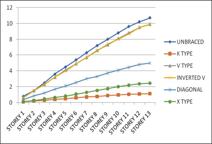
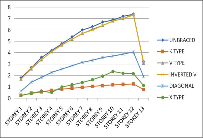

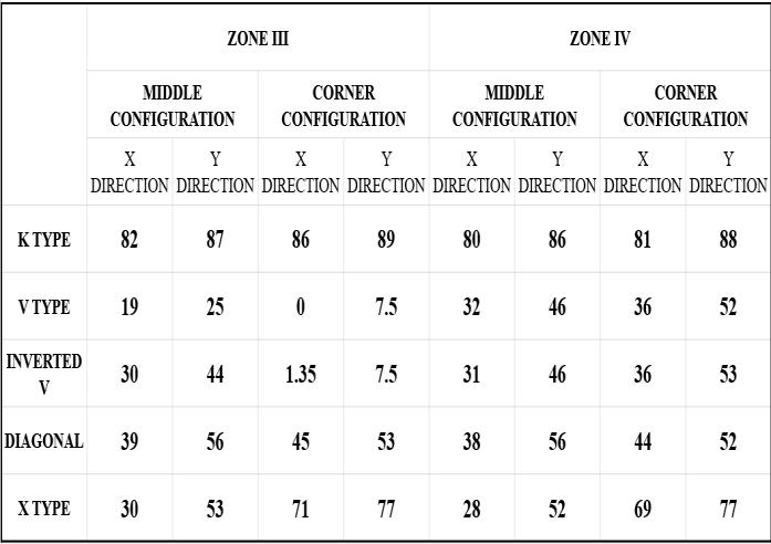
After analysing the unbraced and various braced structures in two different configurations i.e., middle and corner, lateral displacement and storey drift at both zone III and zone IV are compared to each other and the percentagereductionforeachbracingcomparedtothatof unbracedstructureisfound,fromwhichthemostsuitable bracingsystemforthegivenstructureisidentified.

4.1 Lateral Displacement
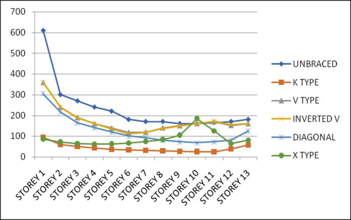
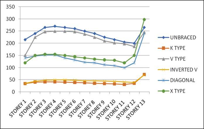
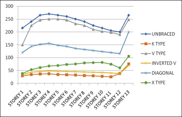
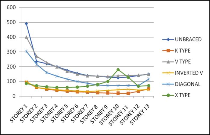
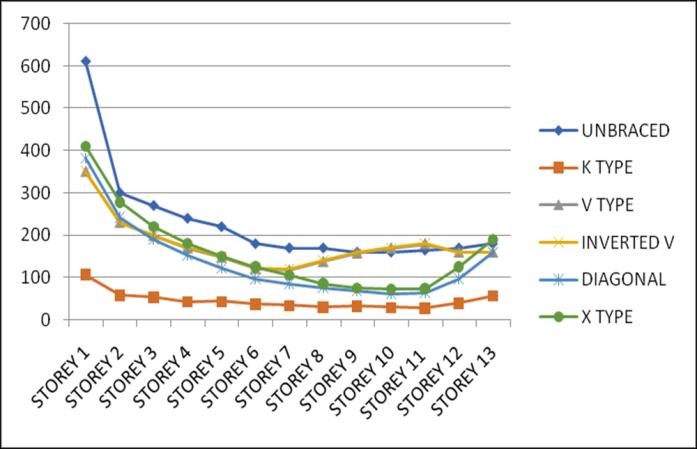
Lateral displacement is the deflection of a single storey relative to the base or ground level of the structure. The variation of Lateral displacement in X and Y direction for Zone III and IV for middle and corner configurations for unbraced structure with that with bracings provided are asgivenbelow.
4.2 Storey Drift
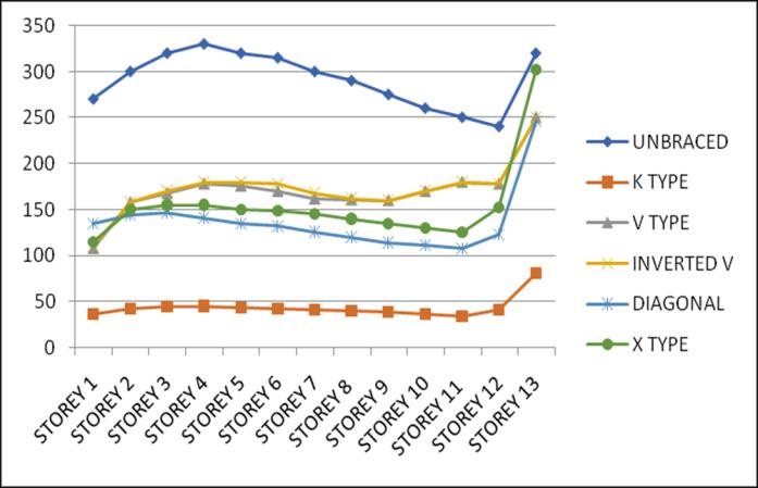
Storey Drift is the displacement of a single storey relative tothestoreyjustbelowit.ThevariationofstoreydriftinX and Y direction for Zone III and IV for middle and corner
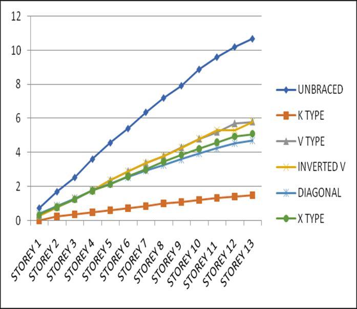
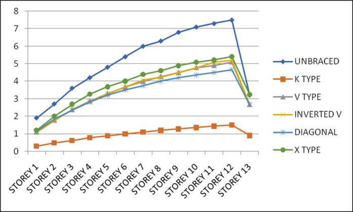
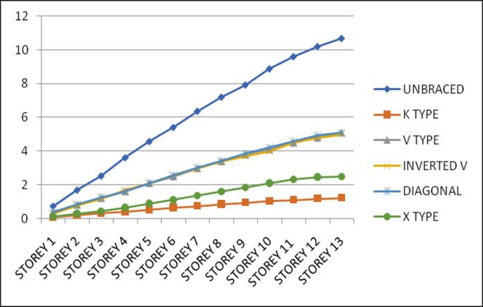
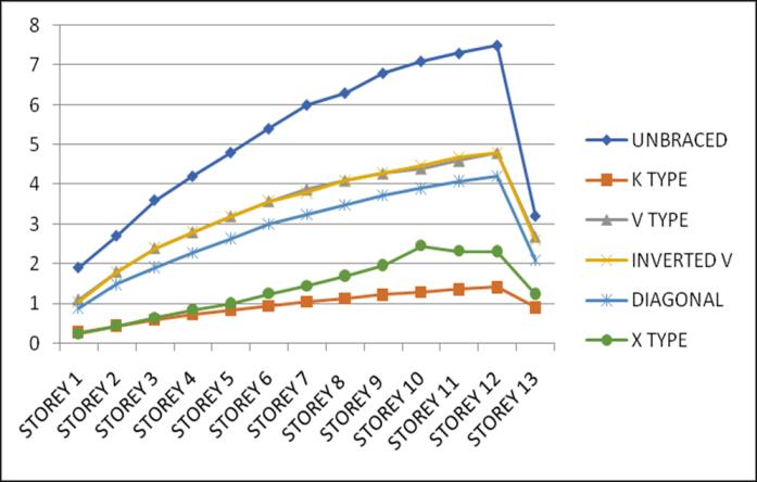
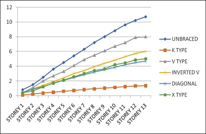

configurations for unbraced structure with that of bracingsprovidedareasgivenbelow.


Xdirection
direction

5. CONCLUSIONS
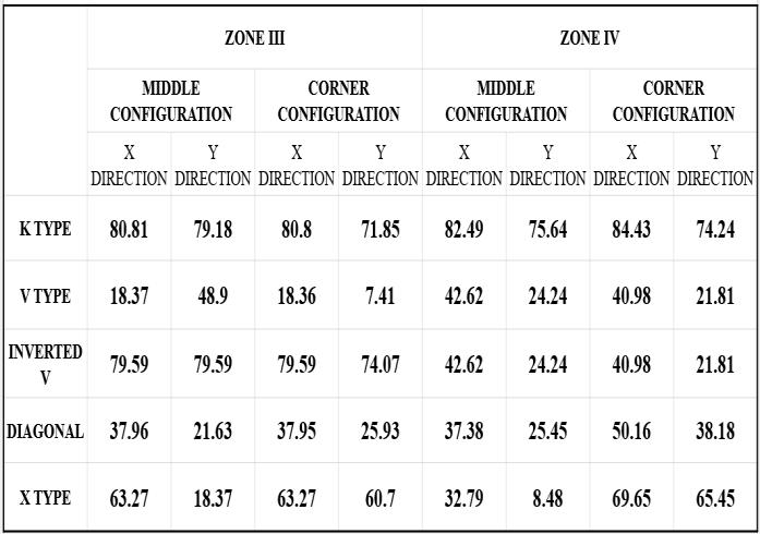
The structure was analysed and concluded that the application of different types of steel bracings in two configurationsdecreasesthedriftandthedisplacement of the structure. For this building K bracing system showed better performance than the other considered bracing systems. Lateral displacement have a percentage reduction of an average of 85% in X and Y direction in both zones III and IV when seismic load is applied in x direction, using K type bracing. Storey drift have a percentage reduction of an average of 79% in X and Y direction in both zones III and IV using K bracing. Identified K type bracing as the most suitable bracing system for resisting the seismic load efficiently for the givenstructure.
REFERENCES
[1] Hyderuddin, M., Imran, M., & Mohsin, S. (2016). Retrofitting of Reinforced Concrete Frames using Steel Bracing. IJSRD-International Journal for Scientific Research&Development,4,2321-0613

[2] Rakshith G M et.al “Analysis of G+20 RC Tall Building in Different Zones using ETABS”, International Journal of Innovative Research in Science, Engineering and Technologyvol8Issue5,May2019
[3] Laguardia, R., & Franchin, P. (2022). Risk-Based OptimizationofBracingSystemsforSeismicRetrofittingof RC Buildings. Journal of Structural Engineering, 148(6), 04022049.
[4] Sharma, M. A. K., & Kumar, m. A. Analysis of G + 30 highrise buildings by using ETABS for various frame sectionsinzoneIVandzoneV

