FORMULATION AND EXECUTION OF A DC TO DC BOOST CONVERTER WITH NON-CONVENTIONAL ENERGY RESOURCE
1Er.Anil, 2Dr. Neha Kapila
1 M.tech Scholar Deptt. Of Electrical Engineering, Sant Baba Bhag Singh University, Khiala Distt: Jalandhar, Punjab, INDIA
2Assistant. Professor Deptt. Of Electrical Engineering, Sant Baba Bhag Singh University, Khiala Distt: Jalandhar, Punjab, INDIA
Abstract - As we all know, due to the distance between the generating power plant station and the demand, there are considerable losses in transporting electrical power. To limit these losses, we use distributed generation. The DG system generates electricity from both conventional and nontraditional sources. With efficiency ranging from 40% to 60%, hydrogen fuel cells are one of the non-conventional energy sources. We also know that hydrogen does not exist in nature, thus it must be created in laboratory. There are various ways to accomplish this. One of this is hydrogen production via the water electrolysis method. We also require power to produce hydrogen, which we obtain from solar panels. A DC-DC Boost Converter is used to accomplish voltage control, allowing the system to provide consistent power.
Keyword: DistributedGeneration(DG),Non-Conventional Energy Resources (NCER), solar power, Dc-Dc Boost Converter,IGBT.

1. INTRODUCTION
In summary, distributed generation (DG) based Nonrenewable energy and renewable energy power production technology has achieved significant progress. However, most renewable energy power generating methods,suchaswindpowerandsolarpowergeneration, are unpredictable and intermittent [1]. If such electricity entersthegriddirectly,theutilitysystem'sstabilitywillbe severely impacted, limiting the usage of connected-grid renewable energy and future development. As a result, several solutions to increase the economics and reliability of various energy conventional sources and renewable energy connected-grid power generating technologies are urgently needed. As an essential distributed power, various energy sources and renewable energy distributed generation should be incorporated in the entire work [2] The expanding potential for DG to grid connections and decarburization of power systems throughout the world suggest that DGs, particularly renewable - based DGs like
windturbine,solarPVmodule,fuelcell,hydropowerplant etc might play a big role in power production's future. Policymakers, grid operators, power system developers, andconsumersarethestakeholderswhoseinterestsmust beaddressedthroughDGintegration.Despitethefactthat integrating DG into the power grid provides advantages such as reduced line loss, increased grid flexibility, costeffective energy generation, and a reduction in the inclination to invest in additional grid assets during capacity development [3]. Because of the diminishing supply of conventional energy resources, last 10 years have become more crucial for the per watt cost of solar energydevices.Itisundoubtedlyexpectedtobecomemore affordable in the future, as technology improves in terms of both cost and applicability. Every day, the planet receives sunlight from above (about 1366W). This is an infinite supply of energy that is free [4]. The primary advantage of solar energy over other traditional power producersisthatsunlightcanbetransformeddirectlyinto solarenergyusingthetiniestphotovoltaic(PV)solarcells. Themostsignificantbenefitofsolarenergyisthatitisfree to the general public and accessible in vast volumes of supplywhencomparedtothepricingofvariousfossilfuels and oils during the last ten years. Furthermore, solar energy requires less manpower than traditional energy productiontechnologies[5].
DC/DC converters are critical components found in renewable energy conversion units as power electronic operatingsystemsforpowerapplications.Mostrenewable energysources(RES),includingphotovoltaic(PV)systems and wind energy, have the lowest voltage output. They require booster circuits to give enough voltage at the output side. The size of the PV current ripple is a crucial aspect in determining the maximum power point (MPPT) [6].
A renewable energy system (RES) converts the energy contained in sunshine, wind, falling water, waves, geothermalheat,orbiomassintoaformthatmaybeused,
such as heat or electricity. Hydrogen-based renewable energy storage may solve the inherent weaknesses of battery-basedenergystoragetechnologiessuchasphysical size,insufficientlifeduration,andtheinitialcapitalcostof the battery bank, as well as transportation, maintenance, and battery disposal difficulties [7]. When renewable resourcesexceedloaddemand,hydrogenwouldbecreated anddepositedbywaterelectrolysis.Anelectrolyzer,which convertswaterintohydrogenandoxygen,isemployedasa fundamentalcomponentofRESforthispurpose.Whenthe loaddemand exceedstherenewable resourceinput,a fuel cell powered by stored hydrogen would provide the balanceofelectricity.Existingenergyfromvarioussources is connected to a low voltage dc bus to guarantee proper powertransmissionbetweensystemmodules [8].Adirect dcbus connection tothe electrolyzer isnotrecommended since it does not provide control of the power flow between the renewable input source and the electrolyzer. To connect the electrolyzer to the system bus, a power conditioning equipment, commonly a dc-dc converter, is required[9]
2. LITERATURE REVIEW

Neha bhagat et al. created a supply circuit for an electrolyzerprocessthatproduced hydrogenusinga dcto dc boost converter. To achieve the highest output voltage level, they employed ideal switches for quick switching responseandZVS(zerovoltageswitching)pulsetopology. Input supply voltage of 40 volts was used from the PV moduleandboosteditto60volts[9].
Atthematlabsimulationtool,PrasannaKumaretal.tooka step toward the modification of a typical dc to dc boost converter by substituting MOSFETs and diodes with four IGBTs and two inductors. They created a circuit that took 48 volts inputfrom a PV module and boosted it to 222.5 volts,achieving91%circuitefficiency.[10].
Antônio Alisson Alencar Freitas et al. created a highvoltage gain dc-dc converter that operated in dependent chip mode (DCM) and does not require electrolytic capacitorstoaccomplishMPPTinPVsystems.Aninductor, a capacitor, and a diode were used for the circuit. The presented topology had several significant advantages, including a low component count, decreased dimensions, and inherent simplicity. The converter efficiency was around 87.5%, with a passive regeneration that was employedtoreducetheswitchinglosses.Theinputvoltage is17volts,whereastheoutputvoltagewasobservedtobe 311volts.Atratedconditions,theaverageinputcurrentIin = 5.82 A, which was much more than the average output currentIout =322mA[11].
Chouetal.proposedtheworktoenhanceenergyefficiency and hydrogen flow rate in the electrolysis process, new evolving DC-DC converters and power management technologies were suggested for implementation. Finally, Pulse width modulation (PWM) change topologies to address power quality, current control, and dynamics response time challenges. Authors suggested that it must be confined to medium voltage application to ensure the maximumpowerefficiency[12].
3. MODELING OF PHOTOVOLTAIC (PV) ARRAY
Solar energy was instantly turned into electricity by the cells.Itismadeupofavarietyofsemiconductormaterials. Positive charge and negative charge are the two different kinds.Solarcellswithhighconversionefficiencyandcheap cost are created using this cell technology. When a solarpoweredcellabsorbsphotons,siliconatoms'electronsare broken loose and dragged away by a grid of metal conductors, which forces an electric current to flow.A PV moduleisthefundamental componentofa PVsystemand is made up of solar cell circuits sealed in an ecologically friendly laminate. To accommodate the energy demand, severalPVmodulesareoftenstackedinseriesandparallel. [13] Following are the specification of PV module used in circuit:-
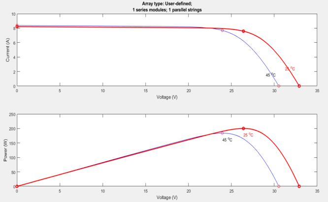
I-V and P-V characteristics of the PV array is helps to determine the MPPT or sometime just power point tracking(PPT)ofthepanel.

Weknowthatwaterisapure resistiveload, thus we employresistanceastheelectrolyzerload.
GraphicallyRepresentationofNoLoadDCandACVoltages
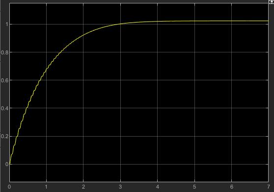
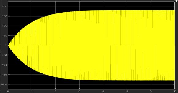
ThecircuitfortheMATLABsimulationofaDCtoDCboost converter is shown in the figure. Tracking the output voltageandcurrentwaveformsatfullloadconditionisthe circuit's goal. The circuit has a 32.69V input voltage and a 226.5V output voltage. The simulation model's source of input voltage is a solar panel with a 200.112 watt power rating,whichisarenewablesourceofelectricity.

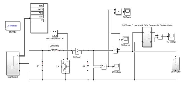
Figure 2 shows how the analysis for the minimal input voltageVin,min=32.69Vundernoloadconditionswithan outputvoltageVo =226.5Vpredictstheperformanceofthe RES model. In the experiment, boost inductor L = 0.02 H andresonantcapacitorsC1 =0.006FandC2 =0.006Fwere utilized as passive parts. Steps increase output voltage by displaying various waveforms captured at no load with a low input voltage 32.69 V. The output voltage decreased from226.5to180.8Vwhen a fullloadwassuppliedtothe circuit, while the solar panel voltage decreased from 32.69V to 26.29V. Because the solar panel is current source so the current in panel is constant and voltage is variable and it will be near about 20%.
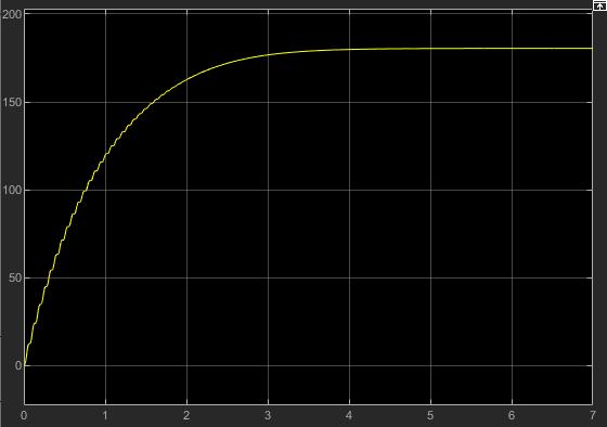
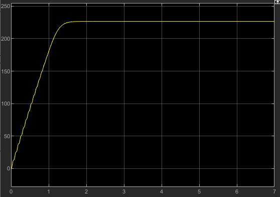
Aspersimulationresultthiscircuitgives92.3%maximum efficiency using signal IGBT with PWM technique and voltagedropupto20.18%.
4. CONCLUSION
This work is the first phase in the investigation of the electrolyzer supply circuit utilizing IGBT switching techniques. The electricity for the electrolyzer supply is supplied by renewable energy resources in the form of a PV array. The PV array produces 32.69V and has a power rating of 200.112 Watt. Using the IGBT-based boost converterintheMATLABSimulationTool,weincreasethe voltage level to 226.5V DC. The circuit consumes 13.85 watts ofpowerinnoloadcondition.Aftersteppingup the DC voltage, we convert it to AC voltage using an IGBTbased converter with PWM generator that consumes 1.029Watt at no load. These alternating current voltages are used for plant auxiliaries. Asweknow, theelctrolyzer worksonstep-updcvoltage,thereforewhenweapplyfull load to it, the output DC voltage drops to 180.8V. We measure a totalof20.18% voltageloss inthecircuit, withamaximumefficiencyof92.35%.
REFERENCES
1.VikasSinghBhadoria,NidhiSingh, Vivek Shrivastava “A Review on Distributed Generation Definitions and DG Impacts on Distribution System” November 2013 International Conference on Advanced Computing and CommunicationTechnologies,Panipat.

2. Zuo Sun, and Xun-you Zhang “Advances on Distributed Generation Technology” Department of Mechanical and Electrical Engineering , Chizhou College, Chizhou city, China.
3. T. Ackermann, V. Knyazkin, “Interaction between Distributed Generation and the Distribution Network: Operation Aspects,” Proceedings of IEEE/PES Transmission and Distribution Conference and Exhibition 2002: Asia Pacific, Yokohama Japan, vol.2, pp.1357-1363, 2002.
4 Mohd Rizwan Sirajuddin Shaikh , Santosh B. Waghmare, Suvarna Shankar Labade , Pooja Vittal Fuke, AnilTekale‘AReviewPaperonElectricityGenerationfrom SolarEnergy‘InternationalJournalforResearchinApplied Science & Engineering Technology (IJRASET) ISSN: 23219653; IC Value: 45.98; SJ Impact Factor:6.887 Volume 5 IssueIX,September2017.
5. Chu Donatus Iweh, Samuel Gyamfi, Emmanuel Tanyi, Eric Effah-Donyina “Distributed Generation and RenewableEnergyIntegrationintotheGrid:Prerequisites, Push Factors, Practical Options, Issues and Merits” School of Engineering, University of Energy and Natural Resources, Sunyani, Ghana.Faculty of Engineering and Technology, University of Buea, Cameroon Published: 29 August2021.
6 Karrar S, Faraj a, Jasim F, Husseinb ‘Analysis and ComparisonofDC-DCBoostConverterandInterleavedDCDC Boost Converter ‘Engineering and Technology Journal Vol.38,PartA(2020),No.05,Pages622-635.
7. Deepak S. Gautam, Ashoka K. S. Bhat, “A Comparison of Soft-Switched DC-to-DC Converters for Electrolyzer Application”, Proceedings of international the IEEE on powerElectronics,vol.28,no.1,pp:54-63,January2013.
8. Burin Yodwong , Damien Guilbert , Matheepot Phattanasak , Wattana Kaewmanee , Melika Hinaje and Gianpaolo Vitale ‘AC-DC Converters for Electrolyzer Applications: State of the Art and Future Challenges’ Institute for High Performance Computing and Networking, Italian National Research Council of Italy, 90146Palermo,Italy.
9. Neha Bhagat, Mr. Gagandeep Sharma “development and implementation of full bridge converter with photovoltaic moduleas an input source” International Journal for TechnologicalResearchinEngineering.
10 Prasanna Kumar C and Anand Raghavendra Rao, “DevelopmentofenergyefficientIBCwithIGBTModulefor Photovoltaic Applications”Power Electronics and Drives, OtisElevatorCompany,PESUniversity,June2020.
11.AntônioAlissonAlencarFreitas,FernandoLessaTofoli, Edilson Mineiro Sá Júnior, Sergio Daher, Fernando Luiz MarceloAntunes‘High-voltagegaindc–dcboostconverter with coupled inductors for photovoltaic systems’issn 1755-4535Receivedon4thJuly2014Revisedon8thApril 2015Acceptedon10thApril2015.
12 Jyh-Horng Chou, C-H Hsieh “Analysis and optimal control of pulse width modulation feedback systems”
Proceedings of the Institution of Mechanical Engineers Part I Journal of Systems and Control Engineering, , National Kaohsiung University of Science and Technology (NKUST),July2004.
13. Shruti Sharma, Kamlesh Kumar Jain, Ashutosh Sharma “Solar Cells: In Research and Applications A Review” Materials Sciences and Applications06(12):1145-1155, January2015.

