PERFORMANCE EVALUATION OF SEMI CIRCULAR SHAPED PATCH ANTENNA USING PROBE FEED TECHNIQUE BY VARYING SUBSTRATE THICKNESS
Parimal Tiwari1, K K Verma2 and Chandan3
1Research Scholar, Department of Physics and Electronics, Dr. Rammanohar Lohia Avadh University, Ayodhya, U.P., India.
2Professor, Department of Physics and Electronics, Dr. Rammanohar Lohia Avadh University, Ayodhya, U.P., India.
3Assistant Professor, Department of ECE, IET, Dr. Rammanohar Lohia Avadh University, Ayodhya, U.P., India. ***

Abstract- In this research article, a semi-circular patch antenna’s performance has been evaluated with respect to S11 parameter and VSWR in which probe feeding technique has been incorporated and also its position is varied along with the substrate thickness. The substrate thicknesses taken are 1.6mm, 2.4mm, 3.2mm and 4.0mm. The antenna dimension is having patch radius of 30mm and the ground size of 50mm X 70mm. The proposed antenna is simulated on IE3D simulator and the S11, VSWR, gain and bandwidth of the antenna at different values of thickness of substrate are presented.
Keywords: Semi-circular,VSWR,S11,gain,IE3Dsimulator.
1. INTRODUCTION:
Intoday'sera ofminiaturization,thereisagrowingneedforantennasthatareconformalandplanarinstructure.Microstrip antennas(MSAs)havegainedsignificantpopularityinpracticalapplicationsdueto theirnumerousadvantages(references1 to 4). In personal communication applications, the demand for compact MSAs is high since the available area for accommodatingtheantennaislimited.
In[5],asemi-circularpatchantennaispresentedinwhichthreebandsareachievedwithwaveportfeedingtechniquetoexcite theantennaandthicknessofsubstrateis1.6mm. somemorecircularandsemicircularantennahavealsobeensimulatedfor deepcharacterization.Thesystematicstudyhighlightsthebehaviorintermsofresonantmodesofshortedpatch[6]. In[7],a new and innovative design is presented for a compact suspended semicircular patch antenna with a half U-slot, allowing for dual-frequencyoperation.Inordertothoroughlyinvestigatethisnovelconfiguration,aparametricstudyisconducted,where the length and width of the slot, as well as the radius and position of the coaxial feed probe, are systematically varied. By incorporatingahalfU-shapedslotintoasemicirculardisk[8],adual-frequencyresonanceantennaisachieved.Theresearch revealsthattheresonancefrequencyoftheantennaisinverselyproportionaltothelengthandfeedpointoftheslot,whereas itincreaseswiththewideningoftheslotwidthandtheradiusofthecoaxialprobefeed. In[9],widebandT-probeproximityfed regular circular and compact semicircular patch antennas are introduced. The research includes experimental measurementsandcomputedresultsobtainedusingthefinite-differencetime-domain(FDTD)method.
Inthisresearcharticle,theinvestigationisperformedontheperformanceofthesemicircularpatchmountedonthesubstrate havingthedielectricconstant4.2byvaryingthethicknessofsubstratefrom1.6mmto4.0mmwiththestepsizeof0.8mm. theVSWRandtheS11parameterhasbeencomparedatallthefourvaluesandthecorrespondingimpedancebandwidthand gainarealsocompared.
2. ANTENNA DESIGN:
The antenna proposed here in this article is designed using the semicircular patch of the radius of 30 mm on the substrate havingthegrounddimensionsof50mmX70mm.the probefeedingtechniquehasbeenincorporatedto excite theantenna. ThesimulationparametersarelisteddownintheTable1mentionedbelow.
ThegeometricaldesignofthesemicircularpatchantennaisdemonstratedinFigure1.

3. RESULT AND DISCUSSION:
3.1 Simulation Results of Semi Circle Shape Patch Antenna with variation in Substrate Thickness

3.1.1 Return Loss vs. Frequency curve:
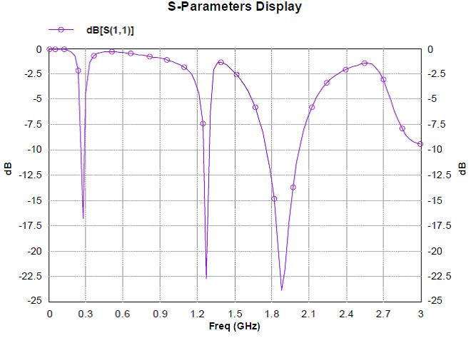
Thereturnlossvsfrequencygraphwithprobelocationx=9.675mm,y=5mm,h=1.6mmisshowninFigure2.Thebandwidth of antenna is calculated on -10 dB. The antenna works in dual frequency mode while the bandwidth of higher mode of frequencyiscalculatedbecauseofhighbandwidthinthisregion.
Fig-2: ReturnlossVsFrequencyCurveofSemiCircularantennaofSubstratethickness1.6mm
Bandwidth Calculation:
fH =2.02203GHz
fL=1.75771GHz
fC= fH+fL /2=1.88987GHz
FractionalBandwidth=13.98%
The fractional bandwidth of antenna is found to be 13.98% at central frequency 1.88987 GHz and at resonant frequency of 1.88326GHz.

3.1.2
VSWR
vs Frequency Curve:
The VSWR vs Frequency Curve is shown in Figure 3. It can be observed from the figure that the VSWR is below two in the operatingfrequencyrange.ThevalueofVSWRatresonatingfrequencyis1.01.
International Research Journal of Engineering and Technology (IRJET) e-ISSN:2395-0056 Volume: 10 Issue: 07 |

3.2 Simulation Results of Semi Circle Shape Patch Antenna with Substrate Thickness of 2.4mm:
3.2.1 Return Loss Vs Frequency curve:
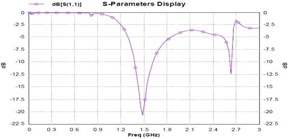
The return loss vs frequency graph with probe location x= 20.65 mm, y=5 mm, h= 2.4 mm is shown in Figure 4. The bandwidthofantennaiscalculatedon-10dB.

Bandwidth Calculation:
fH =1.61894GHz
fL=1.38106GHz
fC= fH+fL /2=1.5GHz
FractionalBandwidth=15.859%
The fractional bandwidth of antenna is found to be 15.859% at central frequency 1.5 GHz and at resonant frequency of 1.48678GHz.

3.2.2 VSWR vs Frequency Curve:
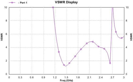
The VSWR vs Frequency Curve is shown in Figure 5. It can be observed from the figure that the VSWR is below 2.0 in the operatingfrequencyrange.ThevalueofVSWRatresonatingfrequencyis1.30
Fig-5: VSWRVsFrequencyCurveofSemiCircularantennaofSubstratethickness2.4mm
3.3Simulation Results of Semi Circle Shape Patch Antenna with Substrate Thickness of 3.2mm:
3.3.1 Return Loss Vs Frequency curve:
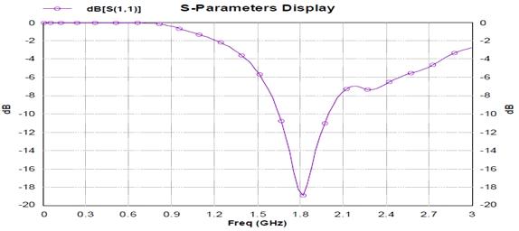
Thereturnlossvsfrequencygraphwithprobelocationx=11.25mm,y=5mm,h=3.2mmisshowninFigure6.Thebandwidth ofantennaiscalculatedon-10dB.
Fig-6: ReturnlossVsFrequencyCurveofSemiCircularantennaofSubstratethickness3.2mm
Bandwidth Calculation:
fH =1.9982GHz
fL=1.6535GHz
fC= fH+fL /2=1.82585GHz
FractionalBandwidth=18.87%
The fractional bandwidth of antenna is found to be 18.87% at central frequency 1.82585 GHz and at resonant frequency of 1.81508GHz.

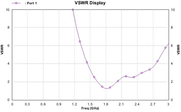
3.3.2 VSWR vs Frequency Curve:
The VSWR vs Frequency Curve is shown in Figure 7. It can be observed from the figure that the VSWR is below two in the operatingfrequencyrange.ThevalueofVSWRatresonatingfrequencyis1.25
International Research Journal of Engineering and Technology (IRJET) e-ISSN:2395-0056

Volume: 10 Issue: 07 | Jul 2023 www.irjet.net
2395-0072
Fig-: VSWRVsFrequencyCurveofSemiCircularantennaof
3.4 Simulation Results of Semi Circle Shape Patch Antenna with Substrate Thickness of 4.0 mm:
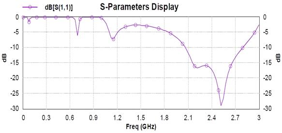
3.4.1 Return Loss Vs Frequency curve:
Thereturnlossvsfrequencygraphwithprobelocationx=11.25mm,y=5mm,z=3.2mmisshowninFigure8.Thebandwidth ofantennaiscalculatedon-10dB.
Fig-8: ReturnlossVsFrequencyCurveofSemiCircularantennaofSubstratethickness4mm
Bandwidth Calculation:
fH =2.7981GHz
fL=2.06167GHz
fC= fH+fL /2=2.42511GHz
FractionalBandwidth=30.249%
The fractional bandwidthof antenna isfound to be30.249%atcentral frequency2.42511GHz andat resonant frequency of 2.51927GHz.

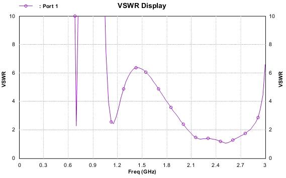
3.4.2 VSWR Vs Frequency Curve:
The VSWR Vs Frequency Curve is shown in Figure 9. It can be observed from the figure that the VSWR is below two in the operatingfrequencyrange.ThevalueofVSWRatresonatingfrequencyis1.06.
International Research Journal of Engineering and Technology (IRJET) e-ISSN:2395-0056

Volume: 10 Issue: 07 | Jul 2023
2395-0072
4. CONCLUSION:
The semicircular patch antenna has been presented in this research article with probe feeding technique. The investigation hasbeenperformedbyvaryingboththeprobefeedingpositionandthesubstratethickness.Itisevidentfromtheresultsthat thebandwidthandthegainareincreasingastheincreaseinthesubstratethicknessishappening.Theoverallsimulationand investigationsareperformedonIE3Dsimulationsoftware.

REFERENCES
[1] I.J.BahlandPrakashBhartia,MicrostripAntennas,ArtechHouse,1980.
[2] G.KumarandK.Ray,BroadbandMicrostripAntennas,Boston:ArtechHouse,2003.
[3] R.Garg,P.Bhartia,I.BahlandA.Ittipiboon,MicrostripAntennaDesignHandbook,ArtechHouse,USA,2001.
[4] C.A.Balanis,AntennaTheory:AnalysisandDesign,2ndedition,JohnWiley&SonsLtd.
[5] S. Ghosh, C. C. Ravindranath and A. V. Pratapkumar, "Semi-circular Microstrip Patch Antenna for Multi-frequency Application," 2014 Fourth International Conference on Communication Systems and Network Technologies, Bhopal, India,2014,pp.6-10,doi:10.1109/CSNT.2014.10.
[6] A. A. Deshmukh, A. P. C. Venkata, A. G. Ambekar and M. Gala, "Design of Compact Semi-circular Microstrip Antenna Loaded with Shorting Post," 2019 9th International Conference on Advances in Computing and Communication (ICACC),Kochi,India,2019,pp.316-321,doi:10.1109/ICACC48162.2019.8986169.
[7] Ray,KamlaPrasanandDeeptiDasKrishna.“Compactdualbandsuspendedsemicircularmicrostripantennawithhalf U‐slot,”MicrowaveandOpticalTechnologyLetters48(2006).
[8] Ansari, Jamshed Aslam, Anurag Mishra and Babau R. Vishvakarma. “Half U-Slot Loaded Semicircular Disk Patch Antenna for GSM Mobile Phone and Optical Communications,” Progress in Electromagnetics Research C 18 : 31-45, 2011.

[9] Guo,Yongming&Luk,K.M.&Lee,Kai-Fong.(2001).“Regularcircularandcompactsemicircularpatchantennawitha T-probefeeding,”MicrowaveandOpticalTechnologyLetters.31.68-71.Doi:10.1002/mop.1360.
BIOGRAPHIES
Mr Parimal Tiwari is a research Scholor in the Department of Physics & Electronics, Dr. RammanoharLohiaAvadhUniversity,Ayodhya,UttarPradesh,India.

Prof. K. K. Verma is Professor in the Department of Physics & Electronics, Dr. Rammanohar Lohia Avadh University, Ayodhya, Uttar Pradesh, India. He did his Ph D from Banaras Hindu University, U.P.Hehaspublishedmorethan80papersindifferentreputedjournalsandconferences.
Dr. Chandan is working as an Assistant Professor in the Department of Electronics and CommunicationEngineering,InstituteofEngineering&Technology,Dr.RamManoharLohiaAvadh University, Ayodhya, Uttar Pradesh, India. He holds a Ph.D in Electronics and Communication Engineering,MadanMohanMalaviyaUniversityofTechnology,Gorakhpur,UttarPradesh,Indiaand hisresearchareasisMicrowaveEngineering(PatchAntenna).Hehaspublishedmorethan40papers inreputedjournal.
