DESIGN ANDDEVELOPMENT OF AUTOMATIC PNEUMATIC BUMPER
Mr.Nitin S. Adwani1, Dr.B.M.Shinde2
1Scholar, Dept of Mechanical Engg, Dhole Patil College of Engineering, Pune, Maharashtra, India
2Professor, Dept of Mechanical Engg, Dhole Patil College of Engineering, Pune, Maharashtra, India ***
Abstract -
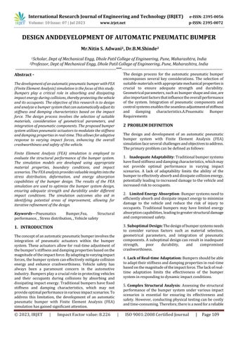
ThedevelopmentofanautomaticpneumaticbumperwithFEA (Finite Element Analysis) simulation is the focus of this study. Bumpers play a critical role in absorbing and dissipating impactenergy duringcollisions, therebyprotectingthevehicle and its occupants. The objective of this research is to design andanalyzeabumpersystemthatcanautomaticallyadjustits stiffness and damping characteristics based on the impact force. The design process involves the selection of suitable materials, consideration of geometrical parameters, and integration of pneumatic components. The proposed bumper system utilizes pneumatic actuators to modulate the stiffness and damping properties in real-time. Thisallowsfor adaptive response to varying impact forces, enhancing the overall crashworthiness and safety of the vehicle.
Finite Element Analysis (FEA) simulation is employed to evaluate the structural performance of the bumper system. The simulation models are developed using appropriate material properties, boundary conditions, and impact scenarios. TheFEAanalysisprovidesvaluableinsightsintothe stress distribution, deformation, and energy absorption capabilities of the bumper design. The results of the FEA simulation are used to optimize the bumper system design, ensuring adequate strength and durability under different impact conditions. The simulation outcomes also aid in identifying potential areas of improvement, allowing for iterative refinement of the design.
Keywords Pneumatics Bumper,Fea, Structural performance,,Stressdistribution,,Vehiclesafety
1. INTRODUCTION
Theconceptofanautomaticpneumaticbumperinvolvesthe integration of pneumatic actuators within the bumper system. These actuators allow for real-time adjustment of thebumper'sstiffnessanddampingpropertiesbasedonthe magnitudeoftheimpactforce.Byadaptingtovaryingimpact forces,thebumpersystemcaneffectivelymitigatecollision energy and enhance crashworthiness. Vehicle safety has always been a paramount concern in the automotive industry.Bumpersplayacrucialroleinprotectingvehicles and their occupants during collisions by absorbing and dissipatingimpactenergy.Traditionalbumpershavefixed stiffness and damping characteristics, which may not provideoptimalperformanceinvariousimpactscenarios.To address this limitation, the development of an automatic pneumatic bumper with Finite Element Analysis (FEA) simulationhasgainedsignificantattention.
The design process for the automatic pneumatic bumper encompasses several key considerations. The selection of suitablematerialswithappropriatemechanicalpropertiesis crucial to ensure adequate strength and durability. Geometricalparameters,suchasbumpershapeandsize,are alsoimportantfactorsthatinfluencetheoverallperformance of the system. Integration of pneumatic components and controlsystemsenablestheseamlessadjustmentofstiffness and damping characteristics.A.Pnuematic Bumper Requirements
2 PROBLEM DEFINITION
The design and development of an automatic pneumatic bumper system with Finite Element Analysis (FEA) simulationfaceseveralchallengesandobjectivestoaddress. Theprimaryproblemcanbedefinedasfollows:
1. Inadequate Adaptability:Traditionalbumpersystems havefixedstiffnessanddampingcharacteristics,whichmay not provide optimal performance in varying impact scenarios. A lack of adaptability limits the ability of the bumpertoeffectivelyabsorbanddissipatecollisionenergy, potentiallyleadingtoincreaseddamagetothevehicleand increasedrisktooccupants.
2. Limited Energy Absorption:Bumpersystemsneedto efficientlyabsorbanddissipateimpactenergytominimize damage to the vehicle and reduce the risk of injury to occupants. Traditional bumpers may have limited energy absorptioncapabilities,leadingtogreaterstructuraldamage andcompromisedsafety.
3. Suboptimal Design: Thedesignofbumpersystemsneeds to consider various factors such as material selection, geometrical parameters, and integration of pneumatic components.Asuboptimaldesigncanresultininadequate strength, poor durability, and compromised crashworthiness.
4. Lack of Real-time Adaptation: Bumpersshouldbeable toadapttheirstiffnessanddampingpropertiesinreal-time basedonthemagnitudeoftheimpactforce.Thelackofrealtime adaptation limits the effectiveness of the bumper systeminrespondingtodynamicimpactconditions.
5. Complex Structural Analysis: Assessing the structural performance of the bumper system under various impact scenarios is essential for ensuring its effectiveness and safety.However,conducting physical testingcanbecostly andtime-consuming.Therefore,thereisaneedforareliable
andefficientmethodtoevaluatethestructuralperformance throughsimulation.
2.1 Objectives:
To improve the adaptability of the bumper system, ensuring optimal energy absorption and dissipation duringcollisions.
Design a bumper system with enhanced energy absorptioncapabilitiestominimizevehicledamageand reducetheriskofinjurytooccupants
To achieve a balanced design that ensures sufficient strength,durability,andcrashworthiness.
Toevaluatethestructuralbehavior,stressdistribution, deformation patterns, and energy absorption capabilitiesofthebumperdesign.
Validatetheperformanceoftheautomaticpneumatic bumper system through experimental testing and comparisonwithsimulationresults.
Theultimateobjectiveistoenhancevehiclesafetyby developing an automatic pneumatic bumper system that effectively absorbs impact energy, minimizes damage, and protects vehicle occupants during collisions.
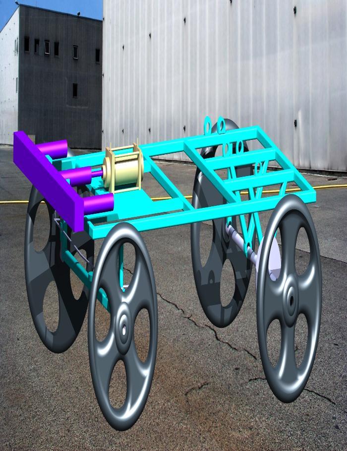
2.2 Methodology:
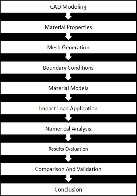
3. FINITE ELEMENT ANALYSIS
The Finite Element Method is a numerical technique employedbyengineerstoaccuratelyaddressthemechanics ofsolidmaterials.Itisa mathematicalmodelingapproach that involves dividing a continuous domain into smaller elements, known as finite elements. These elements are interconnected at nodes to simulate the behavior of the systemunderbothtwo-dimensionalandthree-dimensional movements.
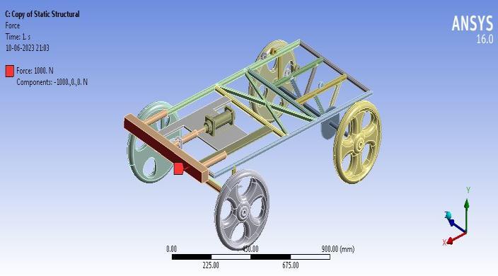
3.1 Boundary Conditions Force
ImpactForcecalculatedis151N
Wewilltake1000N.
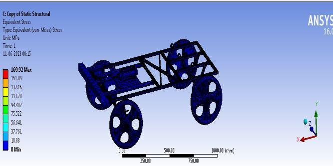
3.2. Post-processing of Structural Analysis
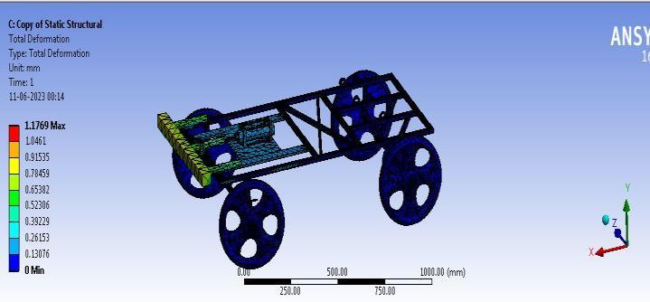
The total deformation contour plot is as shown in below Figure.
TheVon-Misesstressobservedinthemodelis169MPa.
TheanalysisrevealsthattheAutomaticPneumaticBumper experiencesmaximumstressesthatalignpreciselywiththe failurearea.Theevaluationincludesdeterminingtheoverall deformationandequivalentstressvaluesforboththeinitial baseline design and subsequent modified designs of the Pneumatic Bumper. The following table illustrates a comparisonofdifferentdesignsofthePneumaticBumperin FiniteElementAnalysis(FEA)..
The maximum deformation shown by the Automatic PnuematicBumpermodelis1.17mm.
4. CONCLUSION
Acomparativestudywasconductedondifferentdesignsof theElectricVehicleAutomaticPneumaticBumper,leadingto thefollowingconclusions:
ThemodifiedFiniteElementAnalysis(FEA)designof the Pneumatic Bumper exhibits a minimum deformationof1.17mm,whichisincloseagreement withtheexperimentalvalueof1.21mm.
The Von-Mises stress in the modified design of the Pneumatic Bumper is also minimized at 169 MPa, comparedtotheexperimentalvalueof173MPa.
Therefore, based on design and manufacturing considerations, the modified design of the Automatic Pneumatic Bumper is deemed the most suitable and feasiblechoiceforthecurrentapplication.
REFERENCES
1. Pradeep Kumar Uddandapu, "Impact Analysis on Car BumperbyvaryingspeedsusingMaterialsABSPlastic and Poly Ether Imide by Finite Element Analysis softwareSolidworks,"InternationalJournalofModern EngineeringResearch,Vol.3,Issue.1,Jan-Feb.2013,pp391-395.
2. Alen John, Nidhi M.B, "Modelling and Analysis of AutomotiveBumperUsedforaLowPassengerVehicle," International Journal of Engineering Trends and Technology,Volume15,Number7,Sep2014.
3. Yu Zhu et al., "Frontal structure improvement on car based on rear impact test," International Journal of SecurityandItsApplications,Vol.7,No.6,2013,pp.147154.
4. QihuiLi,JikuangYang,"Studyofvehiclefrontstructure crash worthiness on pole impact with different position,"FifthConference onMeasuring Technology andMechatronicsAutomation,2013.
5. Wenhao Mu, Jikuang Yang, "Optimization design of frontal bumper system for Pedestrian lower leg protectionandlowspeedimpactrequirement."
6. Q.H.Maetal.,"ResearchontheCrashSafetyoftheCar Bumper based on different standards," International Journal of Security and Its Applications, Vol.7, No.6, 2013,pp.147-154.
7. JeyanthiandJJanciRani,"HighvelocityImpactanalysis of the thermoplastic bumper in automobiles," InternationalJournalofSecurityandItsApplications, Vol.7,No.6,2013,pp.147-154.
8. Emil Evina, Miroslav, "Comparison of deformation properties of steel sheets for car body parts," ELSEVIER,ProcediaEngineering48,2012,pp.115–122.
9. S.Popprath et al., "Experimental modal analysis of a scaled car body for metro vehicle," International CongressonSoundandVibration,2006.
10. MissPriyaDongare,Prof.Dr.SuhasDeshmukh,"Static and Modal Analysis of composite Drive shaft," International Journal of Engineering Research & Technology,Vol.1Issue10,December-2012.
11. Pawankumar.s, "Modal and staticanalysisofrearcar guard for SUV," International Journal of Engineering Research&Technology,Vol.3Issue7,July2014.
12. Mr.NithinS.Motgi,"Impactanalysisoffrontbumper," International Journal of Engineering Trends and Technology,Volume6Number5,Dec2013.