ANALYSIS OF ANTENNA ARRAYS FOR MILLIMETER WAVE COMMUNICATION
Arpit Yadav1, Mr. Nadeem Ahmad21M.Tech, Electronic and Communication Engineering, GITM, Lucknow, India

2Assistant Professor Electronic and Communication Engineering, GITM, Lucknow, India ***
Abstract - This research combines a front-end RFIC with arrays of antennas operating at 60 and 28 GHz to steer the beam inside a 50-degree arc. Antenna arrays operating at 28 GHz enable 5G's high-speed, broadband data services. In order to send such a large amount of data to the core network through a fixed wireless access (FWA) link, a broadband, highgain, steerable narrow-beam array is required. Antenna arrays at 60 GHz are presented in this thesis for use in FWA and backhaul applications. At 60 GHz (57-66 GHz), the proposed arrays consist of stacked patches and connected slots that are fed by a high gain lens antenna. Over 20 dBi of gain is available from the 216 stacked patches antenna array. The array and RFIC front end combine to provide a module with an EIRP of more than 40 dBm. The other array of 60 GHz antennas has sixteen parallel slots. A high-gain dielectric lens is fed by this source. This antenna has a maximum gain of 25.4 dBi. When the lens is used to deflect the beam away from the broadside, it actually increases in brightness. At 24.25–29.50 GHz, two tiny arrays of antennas transmit and receive. LP and CP arrays may be found in fan-out embedded wafer level ballgrid array (eWLB) packaging. Because the feed lines are shorter and there is no geometrical discontinuity, the antenna in package (AiP) approach saves money compared to PCB arrays and reduces integration losses. The LP array is made up of dipole antennas that are fed into a novel horn-shaped heatsink. The RF module's beam-steering range is 35°, and its peak EIRP is 34 dBm. The CP antenna array is made up of crossed dipoles, and the RF module can steer the antenna's beam by up to 50 degrees.
Key Words: Antenna arrays, Millimeter wave communication,Beamforming,Gain,Channelmodeling,Link budgetanalysis,5Gwirelessnetworks.
1. INTRODUCTION
Millimeter-wavefrequencybandstypicallyrefertotherange of electromagnetic frequencies between 30 GHz and 300 GHz.Thisrangeoffrequenciesishigherthanthosetypically usedfortraditionalwirelesscommunicationsystems,which typicallyoperateinmicrowavefrequencybands(lessthan 30GHz).Themillimeter-wavefrequencybandsofferseveral advantages for communication, including the ability to transmitlargeamountsofdataathighspeeds,aswellasthe ability to support a large number of simultaneous connections. However, these higher frequency bands also present several challenges, including higher atmospheric
absorption, limited range, and sensitivity to blockage by obstacles. Despite these challenges, millimeter-wave communication is becoming increasingly important in applications such as 5G wireless networks, autonomous vehicles,andvirtualrealitysystems,andresearchcontinues toexplorewaystooptimizemillimeter-wavecommunication systemsforreliableandefficientoperation.
The principle of millimeter-wave frequency bands is that theyoperateinthehigh-frequencyrangebetween30GHz and 300 GHz. Millimeter waves have a short wavelength, typicallyrangingfrom1mmto10mm,whichiswhythey arecalledmillimeterwaves.
The use of millimeter waves for communication purposes offersseveraladvantagesoverlowerfrequencybands.For example,millimeterwaveshavealargeavailablebandwidth, whichmeansthattheycantransmitlargeamountsofdataat high speeds. Additionally, millimeter waves have a short range,whichmakesthemidealforuseindenselypopulated areaswhereinterferencecanbeaproblem.
However, millimeter waves have a limited ability to penetrateobstaclessuchasbuildingsandfoliage.Thismeans thattheyarenotsuitableforlong-rangecommunication,and are typically used for short-range, line-of-sight communication applications such as wireless local area networks(WLANs)andpoint-to-pointcommunicationlinks.
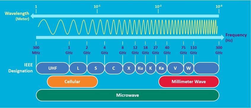
In summary, the principle of millimeter-wave frequency bands is based ontheir highfrequency, short wavelength, largeavailablebandwidth,andshort-rangecommunication capabilities.
The purpose of millimeter-wave frequency bands is to provide high-speed data communication and other applications that require high data rates and low latency. These frequency bands are used for a wide range of applications,including:
1. 5G Wireless Communication: Millimeter-wave frequency bands are a key component of 5G wireless communication networks, which offer fasterdataspeedsandlowerlatencythanprevious generationsofwirelessnetworks.
2. Wireless Backhaul: Millimeter-wave frequency bandsareusedforwirelessbackhaulapplications, whichinvolvetheuseofwirelesslinkstoconnect networkcomponents,suchascelltowersanddata centers.
3. Point-to-Point Communication: Millimeter-wave frequency bands are used for point-to-point communication links, which enable high-speed communication between two points without the needforphysicalcables.
4. Imaging and Sensing: Millimeter-wave frequency bands are also used for imaging and sensing applications, such as airport security scanners, automotive radar systems, and medical imaging devices.
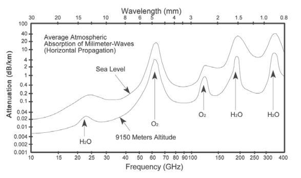
1.1. Moisture Vapourand Oxygen Absorption Cause Mm-Wave Attenuation.
There is a possibility that moisture vapour, which is a component of the Earth's atmosphere, might absorb millimetrewaveswithfrequenciesrangingfrom22GHzto 183GHz.Becausethewatermoleculesintheatmosphereare resonantatthesefrequencies,theyareabletoabsorband scatterthe millimetre wavesthataretransmittedthrough the atmosphere. This resonance is the reason of this absorptionthattakesplace.Thedegreeofattenuationthat takes place may be influenced by the amount of moisture thatispresentintheair,whichmayvarydependingonthe circumstances that are present in the atmosphere at the time.
On the other hand, oxygen absorption takes place at frequencies greater than 60 gigahertz. This is the point at which oxygen molecules in the atmosphere are able to absorbmillimetrewavesandcausethemtoscatteracross thesurroundingspace.Theabsorptionthatoccursatthese frequencies is caused by the spinning resonance of the oxygen molecules. Attenuation may be affected by the amountofoxygenthatispresentintheairinthesameway thatitcanbeaffectedbytheamountofwatervapourthatis presentintheair.
Severaltechniques,suchasoperatingathigherfrequencies, making use of directional antennas, and employing technologies that facilitate beamforming, are utilised in ordertolessentheadverseeffectsthatarebroughtonbythe millimeter-wave signals' capacity to absorb oxygen and water vapour. Additionally, researchers are working to developnewmaterialsandtechnologies,suchasfrequencyselectivesurfacesandmetamaterials,thathavethepotential to lessen the impact of the attenuation that is caused by thesefactors.Thisworkiscurrentlyongoing.
Figure-2: Moisture vapor and oxygen absorption cause mm-wave attenuation
2. ARRAY ANTENNA
An array antenna is a type of antenna that uses multiple individualantennasarrangedinaspecificpatterntocreatea combinedsignalwithincreasedsignalstrength,directivity, andotherdesirablecharacteristics.
In an array antenna, each antenna element is usually connectedtoasingleradiofrequency(RF)chain,suchasa transmitter or receiver. By combining the signals from multipleantenna elements, thearrayantenna canachieve variousantennacharacteristics,suchasbeamforming,beam steering,andspatialfiltering.
Therearevarioustypesofarrayantennas,includinglinear arrays,planararrays,andconformal arrays.Lineararrays aretypicallyusedfordirectionalapplicationsandconsistof aseriesofcloselyspaced,parallelantennaelements.Planar arrays,alsoknownasplanarphasedarrays,arearrangedin a two-dimensional plane and can achieve both directional and two-dimensional scanning. Conformal arrays are designed to conform to the shape of a specific object or surface,suchasthefuselageofanaircraft.
Arrayantennasarecommonlyusedinvariousapplications, includingwirelesscommunication,radarsystems,satellite communication, and radio astronomy. They offer several

advantages over traditional single-element antennas, including improved signal strength, reduced interference, and increased flexibility and control over the antenna radiationpattern.
3. SMALL STRIP PATCH ANTENNA
Asmallstrippatchantennaisatypeofmicrostripantenna that is characterized by a rectangular or square patch of metal that is printed on one side of a dielectric substrate, with a ground plane printed on the opposite side. A small strip patch antenna typically has a length that is much greater than its width, and a feed line or probe is used to connectthepatchtothetransmissionlineorotherelectronic circuitry.
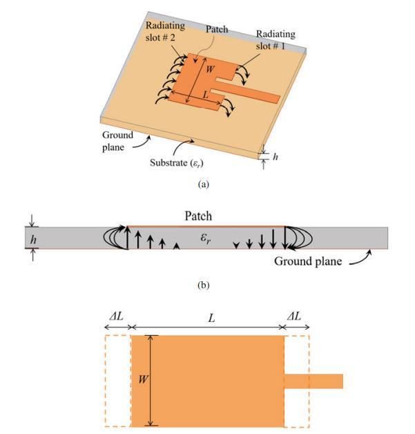
The small strip patch antenna is commonly used for applications that require a low-profile, lightweight, and compactantenna.Theseantennasaretypicallylessthanonetenthofawavelengthinsizeandareoftenusedforwireless communication applications, such as in mobile phones, laptops,andotherportabledevices.
Theperformanceofasmallstrippatchantennaisinfluenced byseveralfactors,includingthesizeandshapeofthepatch, the type and thickness of the dielectric substrate, and the feedpointlocation.Theresonantfrequencyoftheantennais determinedbythedimensionsofthepatchandtheeffective dielectricconstantofthesubstratematerial.
Small strip patch antennas have several advantages over other types of antennas, including low cost, ease of fabrication,andtheabilitytointegratewithotherelectronic components.However,theyalsohavesomelimitations,such as low efficiency and narrow bandwidth, which can limit theirperformanceinsomeapplications.
4. PROBLEM STATEMENT
The rapid advancement in wireless communication technologies,particularlyinthemillimeterwavefrequency range,hascreatedademandforhighlyefficientandreliable antenna systems. Antenna arrays have emerged as a promisingsolutionforachievinghighdatarates,increased systemcapacity,andimprovedcoverageinmillimeterwave communicationsystems.However,thedesign,analysis,and optimization of antenna arrays for millimeter wave communicationpresentseveralchallengesthatneedtobe addressedtofullyexploittheirpotential.

Theproblemathandisthelackofacomprehensiveanalysis and evaluation of antenna arrays specifically tailored for millimeterwavecommunication.Existingresearchprimarily focusesonindividualantennaelementsorsimplisticarray configurations, without considering the intricate characteristics and challenges associated with millimeter wavefrequencies.Thelimitedunderstandingoftheimpact ofarraygeometry,antennaelementspacing,beamforming
techniques,andothercriticalfactorsontheperformanceof millimeterwaveantennaarrayshampersthedevelopment ofoptimalandefficientsystems.
RESULT AND ANALYSIS
Internetconnectivity,mobileconsumersandservices,IoT, HD video streaming, and video chatting increase cellular datacommunicationsdemand.Millimeter-wavebandwidth replacesmicrowavebands.Thisthesis'front-endRFICand 60 GHz and 28 GHz antenna arrays guide the beam ±50° azimuth.28GHz5Gantennaarraysboostbandwidth.FWA transmits high-volume data to the core network from broadband,high-gain,steerablenarrow-beamarrays.This thesisaddressesFWAandbackhaul60GHzantennaarrays. Stacksandslotsfeedahigh-gainlensantennaintwo60GHz (57-66GHz)arrays.20+dBi2×16stackedpatchesantenna array.Arrayandfront-endRFICmoduleEIRPsurpasses40 dBm.Another60GHzantennaarrayfeaturessixteenevenly spacedlinearslots.High-gaindielectriclens.25.4dBipeak gain. Lens scans away from broadside. 24.25–29.50 GHz antenna arrays operate. eWLBs feature LP/CP arrays. ShorterfeedlinesandnogeometricaldiscontinuitymakeAiP technology cheaper than PCB arrays and eliminate
integrationlosses.LParraydipoleantennaspowerahornshapedheatsink.peakEIRPRFmodulebeam-steers±35°.RF module beam-steering is ±50° with 31 dBm peak EIRP. crossed dipoles. LHC accelerators and experiments need faster data rate front-end readout devices. This research explores 60 GHz wireless network CERN data readout. Differentepisodesattack60GHzwirelessdeviceswith17 MeVprotons(7.4Mrad(RX)&4.2Mrad(TX))and200MeV electrons(270&314Mrad).Irradiatedchipsworked.Good resultspromotecomplexwirelesscommunicationsresearch.
6. STACKED PATCHES OF ANTENNA
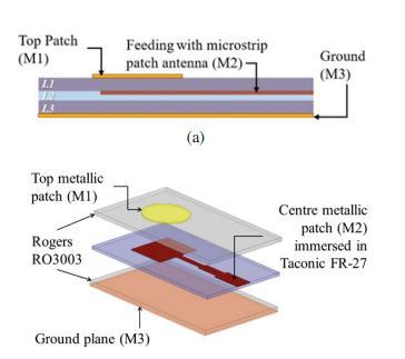
Astackedpatchesantennaisakindofmicrostripantenna that is made up of two or more patch elements that are eitherrectangularorsquareinshape.Thesepatchelements areplacedoneontopoftheother,withadielectricsubstrate in between each layer, to create an antenna that has a stackedappearance.Toconnecteachpatchelementtothe feed line, either a through connection or another kind of electricalconnectionofsomesortisused.
Theperformanceofastackedpatchantennaisdependenton avarietyofcharacteristics,someofwhichincludethesize andshapeofthe patchcomponents,thedistancebetween them,andthedielectricconstantofthesubstratematerial. Otherparametersincludetheshapeofthepatchcomponents and the distance between them. Because multiple patch componentsarepiledatoponeanotherinastackedpatches antenna, it is possible for this kind of antenna to attain superiorgain,awiderbandwidth,andincreasedradiation characteristicswhencomparedtoasinglepatchantenna.
It is possible to construct stackable patch antennas in a numberofdifferentconfigurations,someofwhichinclude theco-planarconfiguration,theparallelconfiguration,and the series configuration, amongst others. In the co-planar configuration,thepatchelementsareplacedsothattheyare allonthesamesideofthesubstrate,whereasintheparallel configuration,thepatchelementsarearrangedsothatthey are all on separate sides of the substrate. The co-planar configurationisthemorecommonofthetwoconfigurations. Intheseriesdesign,thepatchcomponentsareplacedoneon topoftheotherinastackedpattern,withadielectriclayer providing electrical isolation in between each layer. This designisreferredtoasa"stacked"design.
Stackingpatchantennasisacommontechniquethatisused in a broad range of applications, such as radar systems, satellite communication, and wireless communication, amongstothers.Whencomparedtoothertypesofantennas, theyofferanumberofadvantages,includingaloweroverall cost,an easier manufacturingprocess,and thecapacity to providegreatersignalstrengthandawiderbandwidththan single-patchantennas.One illustrationof these benefits is the capability of receiving frequencies from a wider spectrum.Ontheotherhand,theydohaveafewdownsides, such as a greater level of complexity and a lower level of
efficiencyatparticularfrequencies.Thesenegativesarethe resultofahigherdegreeofcomplexity.

7. BEAM-BOOK GENERATION
Utilisingamotorisedturntabletospintheantennainaplane thatisperpendiculartotheaxisoftheantennaisoneofthe more typical approaches that is used when monitoring beam-steering.Inordertoconstructaradiationpattern,the antennaisfirstlinkedtoasignalsourceandthentoapower metre. Next, the signal power is measured at a number of different angles. The direction of the main lobe, the beamwidth, and the levels of the sidelobes are all crucial factorsforthefunctioningofthebeam-steeringsystem,and they can all be determined by looking at the radiation pattern.
Utilisingaphasedarrayantennaisyetanotherwaythatmay beusedtomeasurebeam-steering.Anantennaknownasa phasedarrayisonethatismadeupofanumberofradiating components,eachofwhichiscapableofbeingindependently controlled to produce a beam that may be aimed in a particulardirection.Adjustingthephaseandamplitude of thesignalsthataredeliveredtoeachradiatingelementofa phased array allows one to steer the beam in a particular direction, which may be used to test the beam-steering performanceofaphasedarray.Afterthis,thesignalpoweris measured at the target angle in order to assess the performanceofthebeam-steeringsystem.
In the next portion of the paper, we will go through the findingsofourinvestigationintotheuseofbeam-steeringon stackedpatchantennaarrays.DuetothefactthattheRFIC splitsthepathsfortransmittingandreceivingsignals,fullduplexcommunicationmaybeaccomplishedwithjusttwo arrays,eachofwhichhassixteenantennas.Inaddition,when the scan angle is raised, the beam widths at -3 dB expand fromroughly6degreesatthebroadsidetonearly11degrees attheextremesofthebeam.
Figure-7: Radiation pattern at various frequencies between 56 GHz and 70 GHz, as measured in the elevation plane (E-plan).
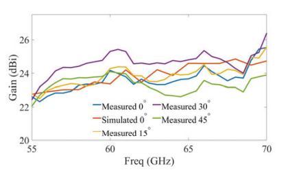
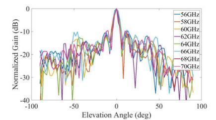
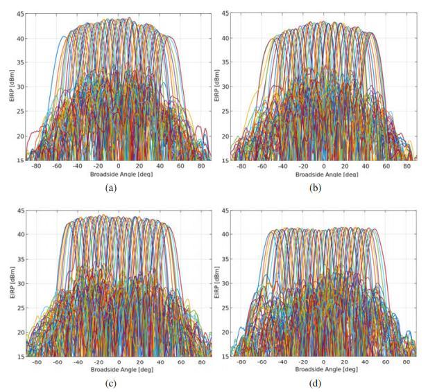
Figure-6: Antenna module supports four WiGig channels and 64 beam emission patterns. At 58.32, 60.48, 62.64, and 64.80 GHz, phase shifters have maximum gain and the signal chain is saturated.

Figure-8: Gain was measured at a variety of beam angles, and simulated gain was also provided for the zero-degree beam.
9. CONCLUSION
Wirelessdatademandisrising,requiringmillimeter-wave frequencyranges.Wirelessdatausehasskyrocketed.Dueto their greater bandwidths, 28 GHz and 60 GHz may meet thesedataneeds,althoughpropagationlosswouldincrease. Lossesneedhigh-gainaerialarrays.Concentratingthebeam requires beam-directing apparatus. This thesis examined 28–60 GHz aerial arrays. Front-end RFIC arrays guide the beamfrom-50degreesto+50degrees.5Gaerialarraysat28 GHzwillprovidehigh-speedinternetservices.Aerialarrays use this frequency. Aerial arrays should give this. Fixed wireless access (FWA) homes and businesses in densely populatedregionswillgettheseservices.Broadband,highgain, steerable narrow-beam arrays require FWA connections. FWA connections move data faster. The primarynetworkgetsthemassivedata.Thisthesisdescribes 60GHzaerialarraysmeetingthesecriteria.They'resuitable forfront-andback-haulcommunications.

Input to a slot linked linearly at sixteen evenly spaced locationscreatesthe60GHzsecondaerialarray.Thisslot feeds an efficient dielectric lens, finishing the process. Weighted 16-degree feeds may azimuth-direct the main beam.Thisrequiresclockwisefeeding.Fourpowersplitters testthedesign'sbeamdirectionat0,15,30,and45degrees. Power splitters direct beams. 0, 15, and 30 degrees. This aerialtested25.4dBi.It'spotential.Thelenseliminatesscan losswhenthebeamisdirectednon-parallel,increasinggain. Something happens when the beam points away from the broadside.
REFERENCE
[1]Cisco.CiscoannualInternetreport(2018–2023)white paper, March 9, 2020. https://www.cisco.com/c/en/us/solutions/ collateral/executive-perspectives/annual-internet-report/ white-paper-c11-741490.html.
[2] GSMA. Mobile internet connectivity 2019 global factsheet, 2019, Accessed on 2020-10-26. https://www.gsma. com/mobile for development/wpcontent/uploads/2019/07/ Mobile-Internet-ConnectivityGlobal-Factsheet.pdf.
[3] Statista. Global mobile data traffic from 2017 to 2022, 2020, Accessed on 2020-10-26. https://www.statista.com/statistics/271405/ globalmobile-data-traffic-forecast/#statisticContainer.
[4] O. Semiari, W. Saad, M. Bennis, and M. Debbah. Performance Analysis of Integrated Sub-6 GHz-Millimeter WaveWirelessLocalAreaNetworks.InGLOBECOM20172017IEEEGlobalCommunicationsConference,pages1–7, 2017.
[5] Rohde Schwarz. 802.11ad - WLAN at 60 GHz A TechnologyIntroduction,WhitePaper.,2017,Accessedon 2021-01-26. https: //scdn.rohdeschwarz.com/ur/pws/dl_downloads/dl_application/applicat ion_notes/1ma220/1MA220_3e_WLAN_11ad_WP.pdf.
[6]GSMA.TheWRCSeries–26GHzand28GHz,Oct2019. Accessed on 2020- 10-27. https://www.gsma.com/spectrum/wpcontent/uploads/2019/10/26-and-28-GHz-for-5G.pdf.
[7]S.Dittmeier,N.Berger,A.Schöning,H.K.Soltveit,andD. Wiedner.60GHzwirelessdatatransferfortrackerreadout systems - First studies and results. Journal of Instrumentation,9(11),2014.
[8]RBrennerandSCheng.Multigigabitwirelesstransferof triggerdatathroughmillimetrewavetechnology.Journalof Instrumentation,5(07):c07002–c07002,jul2010.

[9] H K Soltveit, R Brenner, A Schöning, and D Wiedner. Multi-gigabit wireless data transfer at 60 GHz. Journal of Instrumentation,7(12):C12016–C12016,Dec2012.
[10] R. Brenner, S. Ceuterickx, C. Dehos, P. De Lurgio, Z. Djurcic,G.Drake,J.L.GonzalezGimenez,L.Gustafsson,D.W. Kim, E. Locci, D. Roehrich, A. Schoening, A. Siligaris, H. K. Soltveit, K. Ullaland, P. Vincent, D. Wiednert, and S. Yang. Development of Wireless Techniques in Data and Power Transmission - Application for Particle Physics Detectors. pages1–20,2015.
[11]KarolosPotamianos.TheupgradedPixeldetectorand the commissioning of the Inner Detector tracking of the ATLASexperimentforRun-2attheLargeHadronCollider.In TheEuropeanPhysicalSocietyConferenceonHighEnergy Physics,2016.
[12] S. Dittmeier, R. Brenner, D. Dancila, C. Dehos, P. De Lurgio, Z. Djurcic, G. Drake, J.L. Gonzalez Gimenez, L. Gustafsson, D.-W. Kim, E. Locci, U. Pfeiffer, D. Röhrich, A. Rydberg,A.Schöning,A.Siligaris,H.K.Soltveit,K.Ullaland,P. Vincent, P. Rodriguez Vazquez, D. Wiedner, and S. Yang. Wireless data transmission for high energy physics applications.EPJWebofConferences,150:1–8,2017.
[13] K. C. Huang and D. J Edwards. Millimetre Wave AntennasforGigabitWirelessCommunications,chapter1, pages1–36.JohnWiley&Sons,Ltd,2008.
[14]ZhouyuePiandF.Khan.Anintroductiontomillimeterwave mobile broadband systems. IEEE Communications Magazine,49,2011.
[15] H. T. Friis. A note on a simple transmission formula. ProceedingsoftheIRE,34(5):254–256,1946.
[16]DavidJ.Lockwood.RayleighandMieScattering,pages 1097–1107.SpringerNewYork,2016.
[17] everything RF. 60 GHz long range communication, Accessed on 2020-10-07. https://www.everythingrf.com/community/why-is-the-60ghz-band-not-good-for-long-range-communications.
