
The lattice structure design enables topology optimization of a robotic arm
Abhishek Gupta 1 , Purushottam Sahu 2 , Ghanshyam Dhanera 31Research scholar, BM College of Technology, Indore, MP

2Professor and Head Department of mechanical engineering, College of Technology, Indore, MP
3Professor, Department of mechanical engineering, College of Technology, Indore, MP ***
Abstract -In the fast-paced consumer market, there has been an increasing demand for affordable and personalized products that cater to various needs. These products can be easily manufactured using additive manufacturing, also known as 3D printing, and optimized using the Creo design package and ANSYS software. To reduce weight, the robotic arm has been optimized using topologyoptimizationstrategiesandlatticeconstructions. The ANSYS software is then used to conduct static structuralanalysisonthetopologicallyoptimizeddesign,a genericdesign,andthelatticestructure.Theresultsofthe finite element analysis (FEA) include equivalent stress, deformation, and safety factor. This analysis helps evaluate the impact of reduced mass density on the strength-to-weightratiooftheroboticarm.Acomparative study is then conducted between the generic design and the topologically optimized design based on these parameters.ContourplotsobtainedfromtheFEAanalysis areusedtoidentifycriticalregionswithhighstressesand deformation. The percentage reduction in mass density is compared,andtheeffectofthisreductiononthestrengthto-weightratioisevaluated..
Key Words - FEA, Hydraulic cylinder, Safety factor
1. INTRODUCTION:
ANSYS: ANSYS is a widely used software suite for engineering simulation, including finite element analysis (FEA), computational fluid dynamics (CFD), and other multiphysics simulations. It provides tools for simulating and analyzing the behavior of structures, fluids, and electromagneticsystems.
FEA(FiniteElementAnalysis):FEAisanumericalmethod used to analyze the behavior of complex structures and systemsundervariousloadsandconditions.Itdividesthe structure into smaller, finite elements to approximate the continuous behavior and solve the equations governing the system. FEA is commonly used to predict the stress, deformation,andperformanceofcomponentsorsystems.
Structural Analysis: Structural analysis is a field of engineering that focuses on understanding the behavior and response of structures under different loads and
conditions. It involves analyzing and predicting the stresses, strains, deformations, and stability of structures toensuretheirsafety,performance,anddurability.
Additive Manufacturing: Additive Manufacturing, also known as 3D printing, is a manufacturing process that buildsobjectslayerbylayerusingdigitalmodels.Itallows for the creation of complex geometries and customized products by adding material rather than subtracting it. Additive manufacturing has revolutionized various industries by enabling rapid prototyping, cost-effective production,anddesignfreedom.
Topological Optimization: Topological optimization is a computational design approach used to optimize the material distribution within a given design space. It aims toachievethebeststructuralperformancewhilereducing weight or material usage. Topological optimization analyzes the material layout and removes unnecessary materialorredistributesittoimprovetheperformanceof the structure, such as enhancing stiffness, reducing stress concentrations,orminimizingweight.
Theseconceptsandtechniquesareoftenusedtogether to optimize and analyze the behavior of structures, such as roboticarms,components,orproducts.ByutilizingANSYS software and conducting FEA, engineers can simulate and evaluate the performance of structures, including those manufactured through additive manufacturing methods, while also exploring the benefits of topological optimizationtoimprovetheirdesign.
Topological optimization is a computational design method used to determine the optimal material distribution within a given design space. It aims to maximizetheperformanceofastructurewhileminimizing its weight or material usage. By analyzing and optimizing thetopology(i.e.,thearrangementofmaterial)withinthe designspace,engineerscanachievedesignsthataremore efficient, lighter, and exhibit improved mechanical properties.
The process of topological optimization typically involves thefollowingsteps:
1. Design Space Definition: The design space is the volume or region within which the optimized structure will be contained. It is typically defined based on the desired constraints and boundaries of thedesignproblem.
2. MaterialPropertyandLoadConditions:Thematerial properties of the structure, such as stiffness and density,aredefined,alongwiththeanticipatedloads and boundary conditions that the structure will experienceduringitsoperation.
3. Density Mapping: The design space is discretized into a finite element mesh, and an initial density or material distribution is assigned to each element within the mesh. Commonly, a binary density mapping is used, where elements are assigned a valueof0(void)or1(solid).
4. Optimization Algorithm: An optimization algorithm is employed to iteratively modify the density distribution within the design space. The algorithm adjusts the material density of elements based on specific criteria, such as minimizing compliance (maximizing stiffness) or maximizing structural performancesubjecttocertainconstraints.
5. Sensitivity Analysis: Sensitivity analysis is performedto evaluate theresponse ofthe structure to changes in the density distribution. It calculates the sensitivity of the objective function (e.g., structuralperformance)withrespecttovariationsin thedensitydistribution.
6. Iterative Process: The optimization algorithm iterates between steps 4 and 5, gradually refining the density distribution to converge towards an optimaldesign.
7. Post-Processing: Once the optimization process is complete, the resulting density distribution is convertedintoageometricshapethatrepresentsthe final optimized design. This shape can then be used as a basis for further detailed design and manufacturing.
Topological optimization has numerous applications across various industries, including aerospace, automotive, architecture, and consumer products. It allows engineers to explore innovative and efficient designs by optimizing material distribution and weight whilemaintainingorimprovingstructuralperformance.
Latticestructuredesignreferstothecreationofstructures with a repeating pattern of interconnected struts or
beams, resulting in a porous or cellular structure. These structures often exhibit a high strength-to-weight ratio and have unique mechanical properties that make them suitable for various applications, such as lightweight components, load-bearing structures, and energy absorptionsystems.
The lattice structure design process typically involves the followingsteps:
1. DesignConsiderations:Thefirststepistodefinethe design requirements and constraints. This includes considering factors such as load requirements, desired mechanical properties, material selection, manufacturing constraints, and geometric constraints.
2. Unit Cell Selection: A unit cell is a basic repeating pattern that defines the geometry of the lattice structure. Various unit cell designs are available, suchascubic,diamond,gyroid,andoctettruss,each with different mechanical characteristics. The selection of the unit cell depends on the specific applicationanddesiredproperties.
3. Topology Optimization: Topological optimization techniques, as mentioned earlier, can be employed to optimize the lattice structure design. This involves determining the optimal material distribution within the design space, ensuring that the lattice structure meets the desired performance criteriawhileminimizingweightormaterialusage.
4. StructuralAnalysis:Oncethelatticestructuredesign is optimized, it is important to perform structural analysis using methods like finite element analysis (FEA). This analysis evaluates the mechanical behaviorofthelatticestructureundervariousloads and conditions, ensuring that it meets the required strength,stiffness,andstabilityrequirements.
5. Manufacturing Considerations: Lattice structures can be manufactured using additive manufacturing techniques, such as 3D printing. Manufacturing considerations include selecting appropriate printing parameters, material choices, and optimization of the manufacturing process to achieve the desired lattice structure design accurately.
6. Post-Processing and Finishing: After manufacturing, post-processing steps may be necessary to remove supportstructures,refinethesurfacefinish,orapply additional treatments to enhance the mechanical propertiesoraestheticsofthelatticestructure.
Lattice structures offer several advantages, including lightweight design, improved mechanical performance,
and efficient material usage. They find applications in industries like aerospace, automotive, biomedical, and architecture, where weight reduction, structural integrity, andcustomizeddesignarecrucialconsiderations.
Robotics is a multidisciplinary field that involves the design, construction, programming, and operation of robots. Robots are machines or mechanical systems that are capable of carrying out tasks autonomously or under humancontrol.Theyaredesignedtoperformawiderange of functions, from simple repetitive tasks to complex operations that require high levels of precision and intelligence.
Keycomponentsandaspectsofroboticsinclude:
1. Robot Hardware: This encompasses the physical structure, mechanical systems, and electronic components that make up a robot. It includes components like sensors (e.g., cameras, proximity sensors), actuators (e.g., motors, pneumatic systems), and the overall mechanical design, which can vary widely depending on the robot's intended function.
2. Robot Software: Software plays a critical role in robotics as it provides the instructions and algorithms that control the robot's behavior. Robot software can range from low-level firmware and drivers to higher-level programming languages and frameworks that enable functions such as perception,decision-making,andcontrol.
3. Sensing and Perception: Robots rely on sensors to gather information about their environment. These sensors can include cameras, lidar, radar, infrared sensors, force sensors, and more. Perception algorithms process the sensor data to understand the robot's surroundings, detect objects, navigate obstacles,andinteractwiththeenvironment.
4. Control and Actuation: Control systems enable robots to execute desired actions based on the information gathered from sensors and processed by perception algorithms. Control algorithms determine how the robot moves and interacts with its environment, ensuring precise and accurate execution of tasks. Actuators, such as motors and robotic arms, are responsible for converting control signalsintophysicalmovements.
5. Robot Programming: Programming robots involves developing software and algorithms to enable various functionalities, such as motion planning, path following, object manipulation, and decisionmaking. Programming languages and frameworks
specific to robotics, as well as general-purpose languages,areusedforthispurpose.
6. ApplicationsofRobotics:Roboticsfindsapplications in numerous industries and domains, including manufacturing, healthcare, agriculture, logistics, space exploration, defense, and entertainment. Industrial robots automate production processes, while surgical robots assist in performing delicate surgeries.Autonomousdrones,self-drivingcars,and exploration rovers are examples of robots used in transportationandexploration.
7. Human-Robot Interaction: Human-robot interaction focuses on enabling seamless and intuitive communication between humans and robots. This includes interfaces, such as touch screens, voice commands,andgestures,aswellassafetymeasures and collaborative robotics, where humans and robotsworktogetherinsharedworkspaces.
Robotics continues to advance rapidly, with ongoing research and development in areas like artificial intelligence, machine learning, computer vision, and autonomousnavigation.Thefieldholdsgreatpotentialfor enhancing efficiency, safety, and convenience across a wide range of industries and improving the quality of life forhumans.
2 Literature Review
The current chapter examines the research conducted by various authors in the field of robotics and its practical applications.Goldenbergetal.[1]developedanexplosives disposal robot designed specifically for hazardous environments.Thisrobotfeaturesawheeledplatformand a winder mechanism that keeps the remote control cable andattachmentsclear.Therobotincorporatesa bulkhead for quick and easy attachment of various end effectors. These end effectors are mounted on a turret mechanism, allowing unlimited rotation, and are coaxial with the windermechanism. The manipulatorarmsection consists of a first arm pivoting approximately 110° and a second arm pivoting approximately 120°. The end effectors includeconnectionsofdifferentlengths,extensionlinks,a wrist and gripper mechanism, an aiming and disruptor mechanism,andamobilesurveillancecamera.Therobot's precision and strength are enhanced by robust, zerobacklash joints, enabling delicate or less delicate actions. The wrist and gripper mechanism, along with the extension links, allow even novice operators to perform dexteroustaskseasily.Thecompact,highlymaneuverable, and cost-effective design of this robot meets the specific requirements of law enforcement, military, and environmentalagencies.
Lee et al. [2] possess expertise in the design and construction of mobile welding robots. Their robot consisted of servo and stepper motors, an ECU, and a microcontroller. With six degrees of freedom, the robot underwentanoptimizationprocesscomprisingcoarseand fine searching steps. The coarse searching process established a feasible parameter region (FPR) that satisfied the geometric design requirements without considering the objective functions. The fine searching stageemployedtheoptimizationstrategyoftheconjugate gradient method to locate the design parameters within the overall FPRs. This proposed technique for calculating task-oriented workspace and achieving optimal design is anticipatedtofindapplicationsintypicalindustrialrobots.

Volpe et al. [3] developed a robot named Rocky 7, equippedwithall-wheeldrivecapabilitiesakintotheMars Rover Prototype. Their research delves into various aspects such as methods, electrical design layout, algorithms, and data science. It provides an overview of the recently created Rocky Mars rover prototype, encompassing its mechanical, electrical, software, algorithmic, scientific instrument, and preliminary testing components. This approach showcases advancements over previous iterations and offers a viable pathway forward
RedZone Robotics Inc. developed the Pioneer robot [4] specifically designed for operating in radiation-exposed environments. This robot's primary purpose is to handle radiation leaks within reactors while retrieving data from the reactor zone. The Pioneer robot is a unique, tethered, bulldozer-like robot that enables remote research. It is equipped with stereo vision for real-time 3D mapping, a core-drilling and sample device, and a range of radiation and other sensor equipment. The team has set November 1998astheanticipatedarrivaldateofthePioneerrobotat Chernobyl.
Xu et al. [5] focused on designing and constructing a movable detachable manipulator for lunar stations. The robot comprises a wheeled mobile base and a detachable manipulatorarmwithgrippersoneachend.Therobotcan transform into a mobile splitter and perform exploratory tasks such as gathering soil samples, studying the lunar surface, and transporting equipment and supplies. When thearmlinkstothemobilebasebygrabbingahandlewith one of its grippers, the manipulator arm can detach from the base and move hand-over-hand along a lunar center structure,enablingtaskssuchasstructureinspection,part delivery,andsimpleassemblytasks.Thepapercoversthe concept, benefits, system development, and software architectureofthisrobot.
Ben-Tzvi et al. [6] present an example of a mechanical hybrid portable robot with an innovative design
perspective that combines parallel and sequential connections. This hybrid mechanism comprises a mobile robot platform for movement and a manipulator arm for manipulation, utilizing both parallel and serially connected linkages. The improved capability of the robot is complemented by an adjustable track tension and suspension mechanism integrated into part of the mobile robot connections, which creates the robot's locomotion subsystem. The mechanical design was evaluated using a virtual prototype created with MSC ADAMS software, assessing the robot's enhanced mobility features through animationsofvariouspotentialactivitiesrequiringdiverse locomotion and manipulation abilities. The design was optimizedbyselectingappropriateoperationalfactorsand components, including weight optimization and defining motortorqueneedsfordifferentrobotconfigurations.The performance of the mobile robot was determined by visualizingitonsimulatedterrainssuchaslevelhighways, barriers, stairs, ditches, and ramps, aiding in the final creation of requirements for producing a full-scale prototype.
3. Research Methodology
4. Result: Robotic arm modelling using CADUsing the designsoftwareCreo,amodeloftheroboticarmassembly is created. The robotic arm assembly's dimensions were obtainedfrompublishedworks[4].


Generic Robotic Arm Design Results
The robotic arm assembly is subjected to FEA analysis, and structural output parameters are established. The robotic arm 1 is where the largest equivalent stress is found according to the FEA analysis. According to figure 6.1,thehighestequivalentstressobtainedis9.594MPa.
The robotic arm 1's dimensions are listed below."Part length(L)=0.45metres"

Partthickness(t)equals0.08metres
Thepart'swidth(b)is0.153metres.
GenericRoboticArmDesignResults
The robotic arm assembly is subjected to FEA analysis, and structural output parameters are established. The robotic arm 1 is where the largest equivalent stress is found according to the FEA analysis. According to figure 6.1,thehighestequivalentstressobtainedis9.594MPa.
Deformation graph for a basic robotic arm programme, Figure6.2
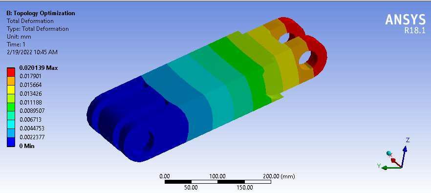
ResultsoftheBeamLatticeRoboticArm
Figure6.5 belowanalysestheroboticarm1usinga beam lattice structure design. At the surface of the load application, a maximum deformation of.027mm is seen. Robotic arm 1's cylindrical support region has low distortion.

Comparative Research
Based on the output parameters, equivalent stress, deformation, and mass, comparison analysis is done for variousroboticarmdesigns.
Table6.1:Comparisonoftheoutcomesforvariousdesigns

5. Thehexagonallatticestructuredesignoftherobotic arm demonstrates a mass reduction of 18.305% when compared to the generic design of the robotic arm.
6. The topologically optimized design of the robotic armachievesasignificantmassreductionof41.48% when compared to the generic design of the robotic arm.
These findings highlight the effectiveness of utilizing lattice structures and topological optimization techniques in achieving weight reduction in the robotic arm design, leadingtoimprovedefficiencyandperformance.
References
[1]. A.Goldenberg, N.Kircanski, S.K.Dickie, G.D.Scott and L.Gryniewski,“Explosive Disposal Robot”, United States Patent number: 6113343, dateofpatent:Sep.5,2000.
[2]. D.Lee, T.W.Seo and J.Kim, “Optimum design and workspace analysis of a mobile welding robot with 3P3R serial manipulator”, Robotics and Autonomous systems, Vol.59,pp.813-826,2011.
[3].R.Volpe,J.Balaram,T.OhmandR.Ivlev,“TheRocky7 Mars Rover Prototype”, Proceedings of IEEE/RSJ International Conference on Intelligent Robots and Systems,OsakaJapan,November1996.
Throughtheutilizationoflatticestructureandtopological optimization techniques, significant weight reduction of theroboticarmcomponentscanbeachieved.Thedetailed findingsareasfollows:

5. Conclusion
1. The topology optimized design and lattice structure design of the robotic arm result in an increase in equivalent stress and deformation compared to the genericdesign.
2. Amongtheoptimizeddesignsoftheroboticarm,the hexagonal lattice design exhibits the highest equivalent stress, while the topologically optimized designdemonstratesthelowestequivalentstress.
3. Amongtheoptimizeddesignsoftheroboticarm,the beam-type lattice design exhibits the highest deformation, whereas the topologically optimized designshowsthelowestequivalentstress.
4. Thebeamlatticestructuredesignoftheroboticarm achieves a mass reduction of 20.11% when comparedtothestandarddesignoftheroboticarm.
[4]. J. Abouaf, “Trial by Fire: Tele-operated Robot Targets Chernobyl”, IEEE Computer Graphics and Applications, pp.10-14,July/August1998.
[5]. Y. Xu, C. Lee and H. B. Brown. Jr, “A Separable Combination of Wheeled Rover And Arm Mechanism”, Proceedings of the IEEE International Conference on RoboticsandAutomation,Minneapolis,USA,April1996.
[6].P.Ben-Tzvi,A.A.GoldenbergandJ.W.Zu, “Designand Analysis of a Hybrid Mobile Robot Mechanism with Compounded Locomotion and Manipulation Capability”, ASME,JournalofMechanicalDesign,Vol.130,July2008.
[7]. S. A. A. Moosavian, A. A. Nazari and A. Hasani, “Kinematics and Workspace Analysis of a Novel 3-DOF SpatialParallelRobot”,IEEE,2009.
[8]. T. Liu, X. Zeng and Z. Ke, “Design and Prototyping a Harvester for Litchi Picking”, IEEE Fourth International Conference on Intelligent Computation Technology and Automation,2011.
[9]. T.C. Manjunath, “Design and Development of a Mobile Rover- OCTAGON”, International Journal of Computer Applications,Volume13–No.3,January2011.
[10].Y.D.SongandJ.Hou,"AGGIEROVER:MobileRobotDesignandTest”,IEEE,pp.39-43,April2000.
[11]. “Pioneer 3-AT”, Adept MobileRobot, Massachusetts, USA.
[12]. S.Tanni and H.Sasaki, “Robot Hand Driving Mechanism”, United States Patent number: 4492510, date ofpatent:Jan.8,1985.