Ansys-CFX analysis to design the diffuser of a multistage pump
Ajay Chouhan1, Purushottam Sahu 2, Ghanshyam Dhanera 31Research scholar, BM College of Technology, Indore, MP

2Professor and Head Department of mechanical engineering, College of Technology, Indore, MP
3Professor, Department of mechanical engineering, College of Technology, Indore, MP ***
Abstract -Multistage pumps, consisting of a series of impellers connected on a single shaft, play a significant role in global power usage. These pumps are commonly employed for transferring fluids with high head requirements and find applications in various industries, hydro storage energy plants, mine dewatering, and boiler feeding. To ensure economic viability and energy conservation, it is crucial to assess the performance and head loss of multistage pumps. One critical component of these pumps is the diffuser, which increases the fluid pressure as it exits the impeller at high velocity. This study focuses on evaluating the impact of the number of vanes in the diffuser on pump performance and head loss under different operating conditions. Computational fluid dynamics (CFD) is employed for the analysis, utilizing 3D modelscreatedusingCreoParametricsoftwarefordifferent fluid domains of a two-stage pump. The components are individually meshed using ICEM-CFD, and simulation setup is performed using CFX-Pre software. The Ansys CFX solver is used to solve the flow equations, and CFD-Post is employed to acquire pump fluid flow details, calculate variousheads,headlosses,andotherparameters.
Key Words: CFX-Pre software, Computational fluid dynamic,Diffuser,Multistagepump,Impellers.
1.INTRODUCTION
In the current era of rapid industrialization and a fastpaced world, the efficient supply of fluid with high head requirements is essential for numerous applications. Multistage pumps have emerged as a popular choice for such tasks, given their ability to handle high-head fluid transfer. Conducting performance analysis and studying head losses in these pumps not only brings economic benefits but also contributes to energy conservation, considering the significant share (approximately 22 percent) [2] of global energy consumption attributed to multistagepumps.Therefore,thisstudyaimstoassessthe behavior of head losses in different components of a multistage pump, particularly focusing on the impact of the number of vanes in the diffuser, across various operating conditions. The investigation involves a numerical simulation analysis of a two-stage centrifugal pump, followed by a comprehensive study of head losses andperformanceparameters.
Apumpisamechanicaldeviceusedtotransportfluids fromoneplacetoanother.Itworksbycreatingapressure difference that propels the fluid through a system. Pumps are widely used in various industries, including water supply, oil and gas, chemical processing, and wastewater treatment.
Therearedifferenttypesofpumps,suchascentrifugal pumps, positive displacement pumps, and axial flow pumps.Centrifugalpumpsarethemostcommonandwork byusinganimpellertogeneratecentrifugalforce,pushing the fluid outward. Positive displacement pumps, on the otherhand,useamechanismtotrapandtransportfluidin discrete volumes. Axial flow pumps operate by propelling fluidparalleltothepumpshaft.
Pumps play a critical role in many applications, including waterdistribution,irrigation,heatingandcoolingsystems, fueltransportation,andindustrialprocesses.Theycomein varioussizesandcapacitiestomeetspecificrequirements. Efficient pump design, maintenance, and operation are essential to ensure optimal performance and energy efficiency.
Pumpscanbeclassifiedintodifferentcategoriesbasedon various factors such as their principle of operation, fluid handling capabilities, and design characteristics. Here are somecommonclassificationsofpumps:
1. BasedonPrincipleofOperation:
Centrifugal Pumps: These pumps use centrifugal force generated by a rotating impeller to move fluid. They are widely used for low to medium viscosity fluids and high flowrates.
Positive Displacement Pumps: These pumps trap and transport fluid in discrete volumes, creating a pulsating flow. They are suitable for high viscosity fluids and applicationsrequiringpreciseflowcontrol.
AxialFlowPumps:Thesepumpsmovefluidparalleltothe pump shaft, using propeller-like blades. They are suitable forhighflowratesandlowtomediumheadapplications.
BasedonFluidHandling:
Water Pumps: These pumps are specifically designed for handling water,includingclean waterpumps,wastewater pumps,submersiblepumps,andboosterpumps.
Chemical Pumps: These pumps are designed to handle corrosive or abrasive fluids, including acids, solvents, and chemicals. They are typically made of materials resistant tochemicalattack.
SlurryPumps:Thesepumpsareusedforpumpingslurries, which are mixtures of solid particles and liquid. They are designedtohandlehighconcentrationsofsolids.
2. BasedonDesignCharacteristics:
Single-stage vs. Multistage Pumps: Single-stage pumps have only one impeller, while multistage pumps have multiple impellers arranged in series. Multistage pumps arecapableofgeneratinghigherpressures.
Vertical vs. Horizontal Pumps: Vertical pumps have a vertically oriented shaft, while horizontal pumps have a horizontally oriented shaft. The choice depends on space availabilityandinstallationrequirements.
Eachtypeofpumphasitsownadvantagesandlimitations, andtheselectionoftheappropriatepumpdependsonthe specific application requirements, fluid properties, flow rate,andpressureconsiderations.
Analyze the impact of the number of diffuser vanesonthepump'sperformanceandheadloss.
3. Analysis


Theprimaryfocusofthisworkistoassessthedesignand performance of the multistage pump by investigating the effects of varying diffuser vanes and discharges. Through numerical simulations and analysis, valuable insights will be gained regarding the head loss characteristics and overallperformanceofthepump.

2. Objective of the Current Work:

Evaluate and optimize the design of a multistage pump.
Perform numerical simulations of a two-stage multistage pump with varying numbers of diffuservanesatdifferentdischargeconditions.
StreamlinePatternsAnalysisfora2-StagePump:
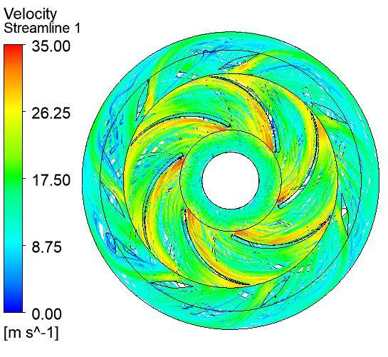
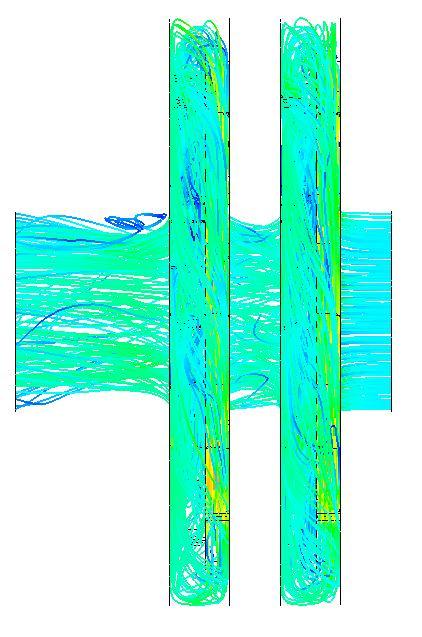
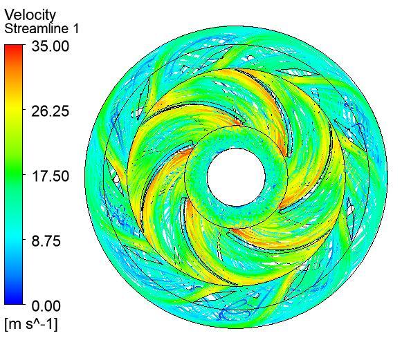
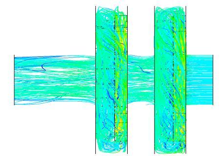
The streamline patterns were examined at the optimal efficiency point for each configuration of diffuser vanes. These patterns provide insights into the flow behavior within the pump. It is observed that the pump's inlet generates suction, resulting in fluid being drawn in at a high velocity. Consequently, the fluid particles exhibit higher velocities at the pump's intake compared to the outlet. Additionally, the influence of impeller rotation on

expellingfluidfromthedomainleadstoincreasedvelocity attheimpellerexit.

3.2 Streamline Patterns for 7 Diffuser Vanes: Figure 3.2 (a)and(b)depictthevelocitystreamlinesintheradialand axialplanes,respectively,fortheconfigurationwithseven diffuser vanes. The kinetic energy from the rotating impeller contributes to higher fluid velocities within the impeller. In the diffuser section, the velocity decreases by 4.42 m/s, resulting in a smooth flow in the pump flow channels.
3.2StreamlinePatternsfor8DiffuserVanes:Figure3.2(a) and (b) illustrate the velocity streamlines for the configuration with eight diffuser vanes in the radial and axial planes, respectively. Similar to the previous configuration, the impeller's kinetic energy elevates the fluidvelocitywithintheimpeller.Thevelocityreductionin the diffuser is measured at 4.39 m/s, achieving a smooth flowinthepumpflowchannels.
5.7.3StreamlinePatternsfor9DiffuserVanes:Figure5.23 (a) and (b) display the velocity streamlines in the radial and axial planes, respectively, for the configuration with nine diffuser vanes. The impeller's kinetic energy contributes to higher fluid velocities within the impeller, while the diffuser reduces the velocity by 4.52 m/s, resultinginasmoothflowinthepumpflowchannels.
5.7.4 Streamline Patterns for 10 Diffuser Vanes: Figure 5.24 (a) and (b) showcase the velocity streamlines in the radial and axial planes, respectively, for the configuration with ten diffuser vanes. The impeller's kinetic energy promoteshigherfluidvelocitieswithintheimpeller, while the diffuser reduces the velocity by 4.51 m/s, ensuring a smoothflowinthepumpflowchannels.


5.7.5 Streamline Patterns for 11 Diffuser Vanes: Figure 5.25 (a) and (b) demonstrate the velocity streamlines in the radial and axial planes, respectively, for the configuration with eleven diffuser vanes. Similar to the previous configurations, the impeller's kinetic energy leads to increased fluid velocity within the impeller. The diffuser section reduces the velocity by 4.60 m/s, achievingasmoothflowinthepumpflowchannels.
These streamline pattern analyses provide valuable insights into the flow characteristics and efficiency of the 2-stage pump for different configurations of diffuser vanes.


4. Conclusion:
Based on the comprehensive simulation process and analysis of the above-discussed parameters, the following conclusionscanbedrawn:
I. At 1900 rpm and for 6 different discharges, the evaluation of 5 different numbers of diffuser vanes revealed that the best efficiency was achieved with 7 diffuservanesataflowrateof630m3/h,whilethelowest efficiencywasalsoobservedwith7diffuservanes.
II. The diffuser's performance seems to be influenced by the odd number of vanes, which performs better comparedtoanevennumberofvanesintheimpeller.This couldbeattributedtotherelativeangularpositionsofthe diffuserandimpellervanes.
III. The head values for discharges of 580, 630, and 700 m3/h are almost similar across all vanes. Hence, it can be concluded that the impact of the diffuser's number of vanesontheheadisminimalathigherflowrates.
IV. The size reduction of the diffuser channel significantly affectstheperformanceofthemultistagepump.
V. Considering all the aforementioned criteria, the multistage pump with nine vanes in the diffuser demonstrates a slight advantage over pumps with fewer vanes.
VI. The relative positioning of the impeller and diffuser vanes has a significant influence on the results obtained fromthenumericalmodelingofthemultistagepump.
These conclusions provide valuable insights into the design and optimization of multistage pumps, specifically regarding the number of diffuser vanes and their impact onthepump'sperformanceandefficiency.
Scope of the Work:
Gather necessary design information such as pumpsizingandboundaryconditions.
Developa3Dmodelofthemultistagepumpusing Creo parametric software and generate meshes forallitscomponentsusingICEM-CFD.
Conductpreliminaryprocessingandsimulationof the two-stage pump with different combinations ofdiffuservanesanddischargerates.
Evaluate and analyze the results of head loss and performancemetricsofthemultistagepump.
REFERENCES
1. Elikalfa, A, &Karaismail, E, (2019). “Design and optimization of a centrifugal pump impeller with ansys–optislang”. ARGEDergisi
2. European Commission (2001). “Study on improvingtheenergyefficiencyofpumps”.
3. Gülich, J. F. (2008). “Centrifugal pumps”, Berlin: Springer, 02.
4. Hernandez-Solis, A., &Carlsson, F. (2010). “Diagnosis of submersible centrifugal pumps: a
motor current and power signature approaches”. Epejournal,20(1),58-64.

5. http://equipmentschemical.blogspot.com/2014/ 01/centrifugal-pumps-basic-concepts-of.html
6. https://smartturner.ca/pumps/multi-stageheavy-duty-pumps
7. https://www.pipeflow.com/software-technicalsupport/pipe-flow-expert-positive-displacementpumps
https://www.pumpsandsystems.com/what-differencebetween-centrifugal-rotodynamic-pumps
