PERFORMANCE EVALUATION AND ANALYSIS OF FREQUENCY RECONFIGURABLE DIELECTRIC RESONATOR ANTENNA
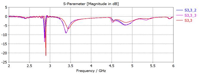
KM NEHA VERMA1, Dr. RISHI ASTHANA2Abstract - In this line of investigation, the initial step is to develop a basic dielectric resonator antenna that has microstrip strips attached to two of the edges of the dielectric resonator. The value of rr = 10 is used to represent the dielectric constant of the DR, which has dimensions of 13 mm 13 mm 10 mm. The DR is positioned on a ground plane with dimensions of 100 millimetres by 150 millimetres and a substrate with a rr value of 3.38. There are six distinct working conditions that may be accomplished by placing shorting tabs along one edge of the DRA. Second, a frequency reconfigurable DRA in the form of a H that uses coplanar waveguide (CPW) feed is given here. This antenna is made up of two different types of dielectric resonators, each of which has a dielectric constant of 15. On a substrate with a dielectric constant of 3.2, the DRs are positioned. In order to activate the DRA, the CPW feeding approach is used. On the line that connects the dielectric resonators, there are two PIN diodes installed for usage. By using these PIN diodes, it is possible to acquire three different working modes, such as off on, off on, and on on. In the OFF ON state, two bands are obtained, one with a centre frequency of 2.7 GHz for the WLAN application and the other with a centre frequency of 4.8 GHz for the INSAT (Indian national satellite system) use. When the switch is in the ONOFF position, a single narrow band with a centre frequency of 3.7 GHz is produced for use in wireless local area network (WLAN) and international mobile telecommunications (IMT) applications. In a manner analogous, when the ON ON state is selected, a dual band consisting of the frequencies 2.6917 and 5.2589 is produced for use in WLAN applications.
Key Words: reconfigurabledielectricresonatorantennas, frequency analysis, dielectric constant, Finite Element Method,substratematerial,resonancefrequency,microstrip patch antenna, rectangular dielectric resonator antenna, returnloss,radiationpattern.
1. INTRODUCTION
Reconfigurabledielectricresonatorantennas(RDRAs)area typeofantennathatcanbetunedtodifferentfrequenciesby adjustingtheirphysicalproperties.RDRAsarecomposedofa dielectricresonator,whichisapieceofmaterialwithahigh dielectric constant, and a conducting element, such as a microstrip patch, that is used to excite the resonator. By changing the dielectric constant of the resonator, the resonantfrequencyoftheantennacanbeadjusted.RDRAs havebeenshowntohavesuperiorperformancecomparedto
other types of antennas, particularly in terms of their radiationpatternandreturnloss.Theyareusedinavariety of applications, including wireless communication, radar systems,andsatellitecommunicationsystems.
Theprincipleofreconfigurabledielectricresonatorantennas (RDRAs) is based on the ability of dielectric materials to affecttheresonantfrequencyoftheantenna.Whenahigh dielectric constant material is placed near a conductive structure, it creates a resonant structure with a specific resonantfrequency.Bychangingthedielectricconstantof thematerial,theresonantfrequencyofthestructurecanbe adjusted.
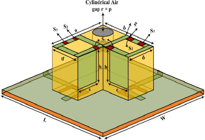
RDRAs consist of a dielectric resonator and a conducting element,suchasamicrostrippatchoraslot.Thedielectric resonatorisapieceofhighdielectricconstantmaterialthat is excited by the conducting element. By changing the dielectricconstantoftheresonator,theresonantfrequency oftheantennacanbetuned.
There are several methods for changing the dielectric constant of the resonator in RDRAs, including the use of varactordiodesormicro-electromechanicalsystems(MEMS)

switches.Varactordiodesareusedtochangethecapacitance of the resonator, which in turn changes the resonant frequency.MEMSswitchesareusedtochangetheshapeof theresonator,whichalsoaffectstheresonantfrequency.
Overall, the principle of RDRAs is to create a resonant structure that can be tuned to different frequencies by adjustingthedielectricconstantofthematerial.Thisallows forahighlyversatileandadaptableantennathatcanbeused inawiderangeofapplications.
Thepurposeofreconfigurabledielectricresonatorantennas (RDRAs)istoprovideaflexibleandadaptablesolutionfor wireless communication systems, radar systems, and satellitecommunicationsystems.

RDRAs offer several advantages over traditional fixedfrequencyantennas,includingtheabilitytotunetomultiple frequencies without the need for physically changing the antennastructure.Thisflexibilityallowsforasingleantenna tobeusedformultipleapplications,reducingtheneedfor multipleantennasandsimplifyingthedesignandinstallation process.
1.1. Factor Affecting Reconfigurable Dielectric Resonator Antennas
Thereareseveralfactorsthatcanaffecttheperformanceof reconfigurable dielectric resonator antennas (RDRAs), including:
1. Dielectric Constant: The dielectric constant of the materialusedintheresonatoraffectsthefrequency at which it resonates. By changing the dielectric constantofthematerial,theresonantfrequencyof theantennacanbetuned.
2. Resonator Geometry: The size and shape of the resonatorcanalsoaffecttheresonantfrequencyof the antenna. Changing the geometry of the resonatorcanchangetheresonantfrequencyofthe antenna.
3. SubstrateThickness:Thethicknessofthesubstrate usedintheantennacanaffectitsradiationpattern andimpedancebandwidth.
4. FeedingTechnique:Thewayinwhichtheantennais fedcanalsoaffectitsperformance.Differentfeeding techniques can be used to achieve different radiationpatternsandimpedancebandwidths.
5. ReconfigurationMechanism:Themechanismused to reconfigure the antenna can also affect its performance.Forexample,someRDRAsuseMEMS switchestoreconfigure the antenna, while others usevaractorsorothertypesoftunablecomponents.
6. Operating Environment: The operating environment,includingfactorssuchastemperature, humidity, and electromagnetic interference, can alsoaffecttheperformanceofRDRAs.
1.2. Limitation of DRAs
One limitation of DRAs is their narrow bandwidth. The resonantfrequencyoftheDRAishighlydependentonthe dielectricconstantofthematerialusedintheresonator.This canleadtoanarrowbandwidththatmaynotbesufficient forsomeapplications.Varioustechniques,suchasmultiple resonatorstructuresand theuse ofmetamaterials,can be usedtobroadenthebandwidthoftheDRA.
Anotherlimitationisthedifficultyinachievingpolarization diversity.DRAsaretypicallydesignedtoradiateinasingle polarization,whichlimitstheirabilitytoreceiveortransmit signalswithdifferentpolarizations.Varioustechniques,such as stacked DRAs and multiport feeding, can be used to achieve polarization diversity, but these techniques can increasethecomplexityandcostoftheantenna.
A further limitation is their sensitivity to surrounding objects.Theradiationpatternandresonantfrequencyofthe DRAcanbeaffectedbynearbyobjects,suchasconductive surfacesandotherantennas.Thiscanleadtoareductionin the antenna's performance and may require careful placementandshielding.
Finally,theuseofhigh-permittivitydielectricmaterialscan limittheoperatingtemperaturerangeoftheDRA.Athigh temperatures,thedielectricmaterialcanexperiencethermal degradation, which can lead to a change in the resonant frequencyandareductionintheantenna'sperformance.
Overall,whileDRAshavemanyadvantages,theirlimitations must be carefully considered in the design and implementationofpracticalantennasystems.
2. PROBLEM STATEMENT
Theproblemathandisthelackofcomprehensiveanalysis and understanding of the design, performance, and optimization of frequency reconfigurable dielectric resonatorantennas.Existingresearchinthisfieldprimarily focuses on individual aspects of FR-DRAs, such as reconfigurable materials, tuning mechanisms, or specific frequencybands.However,asystematicinvestigationthat encompassestheoveralldesignconsiderations,operational characteristics, performance limitations, and optimization techniquesforFR-DRAsislacking.
Moreover, the design of FR-DRAs is inherently complex, involving a multitude of parameters and trade-offs. The selectionofsuitablereconfigurablematerials,theintegration of tuning mechanisms, and the determination of optimal controlstrategiesrequirein-depthanalysisandevaluation.
Theimpactofthesedesignchoicesonantennaperformance metrics, such as radiation pattern, gain, bandwidth, and efficiency, needs to be thoroughly investigated to develop practicalguidelinesanddesignmethodologiesforFR-DRAs.

3. RESULT AND ANALYSIS
First, microstrip strips are affixed to the perimeter of a simple dielectric resonator antenna. The DR measures 13mmx13mmx10mmandhasarr=10dielectricconstant. TheDRismountedona100mmx150mmsubstratewithrr =3.38.ToswitchbetweentheDRA'ssixmodes,justshort the tabs along one edge. The second kind is a DRA that is suppliedbyacoplanarwaveguide(CPW)andhasavariable operatingfrequency.Thisantennaconsistsoftwodielectric resonators,eachhavingadielectricconstantof15.TheDRs aresupportedbyasubstratewithadielectricconstantof3.2. TheCPWfeedingmethodhelpstoraisetheDRA.Toconnect thedielectricresonators,twoPINdiodesareusedinawire. ThesePINdiodeshavethreepossibleoperatingstates:offon,on-off,andon-on.WhentheswitchisintheONposition, itacquiresa2.7GHzbandforwirelesslocalarea network (WLAN) usage and a 4.8 GHz band for use with INSAT (India'snationalsatellitesystem).Asingle,narrowbandat 3.7 GHz, usable for WLAN and IMT, is created by toggling betweena"ON"and"OFF"setting.Similarly,intheONON state,adualbandwithfrequenciesof2.6917and5.2589is formedforWLANapplications.
4. FIRST DESIGNOF FREQUENCY RECONFIGURABLE DIELECTRIC RESONATOR ANTENNA
First design employs edge-grounded dielectric resonator antenna.Figure5showsedge-grondedDRA.Oneedgerests. Thisshortingwallalignselectricandmagneticfieldsnormal and tangential to the conductor, as shown. Walls shorten resonance frequency. Shorting the wall decreases the resonance frequency from 5 GHz to 3.5 GHz in the recommendedconfiguration.
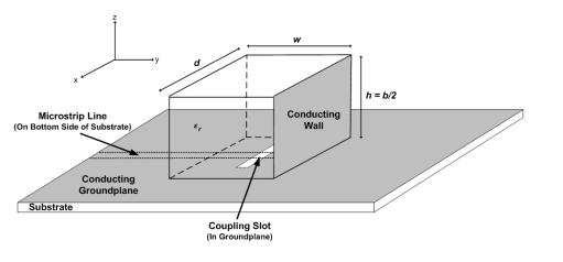
4.1. Simulation Result of First Proposed Antenna
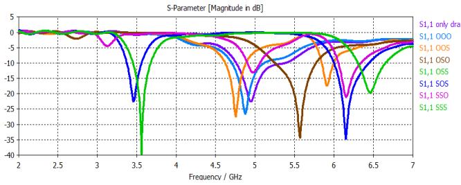
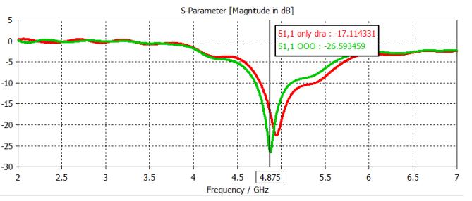
TheonlycomponentthatisthrilledtostartwithistheDRA because, when employing the configuration that was just explained,whichresultsinafrequencyof4.945GHzanda return loss value of -22.59 dB, the DRA is the only componentthatisexcited.Thefinalresultisequivalentand hasareturnlossof-26.59whentwomicrostripstripsare added to each side of the DRA. The incorporation of the microstrips brings about this result. Doing this step is essential in order to bring the circuit to a successful conclusion.
5. SECOND DESIGN OF COPLANAR WAVEGUIDE-FED H-SHAPED FREQUENCY RECONFIGURABLE DRA

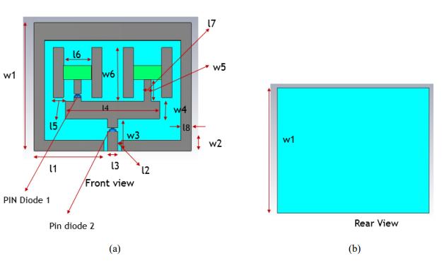
5.1. The Proposed Antenna's Geometry
Dielectricresonatorsflankbothsidesoftheaerial.TheDRA isincreasedwiththehelpoftheCPWfeedingapproach.The DRA is protected on both sides by microstrip holes. A Taconic substrate, with a dielectric constant of 3.2 and a thicknessof1.6,ispositionedunderneaththefeedline.
INSAT. Both of these bands may be used to communicate usingradiowaves(theIndiannationalsatellitesystem).

6. THIRD DESIGN
6.1. Geometry for Suggested Antenna.
Thisdesignemploystwodielectricresonatorswithdifferent diametersbutthesamedielectricconstant(10).Dielectric resonatorsover0.05-mmgroundplanes.Aperturecoupling feedingexcitesDRAs.Groundplaneapertureslotsbelowthe DRA activate two dielectric resonators. Feed-from-below. Power divider concept excites DRAs simultaneously. Feed networks link DRAs to inputs. 50 quarter wavelength convertersateachfeednetworkendrecreatea50-ohmline divided into 100. Dielectric resonators receive power equally.
Switchlessaerialtesting.2.9GHzWLAN.ThefirstDRAis20 mmx20.3mmx6.7mmandthesecondis14mmx8mmx 8.10.
5.2.
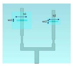
Thesnapshotthatwassuppliedtoyouhadtheonlypurpose of illustrating the difference between the OFF and ON positions in order to make the procedure more understandableforyou.Thisresultsintheacquisitionoftwo bands,eachofwhichhasadistinctcentrefrequency:2.7GHz for use with WLAN, and 4.8 GHz accordingly, for use with
WLANapplicationsutilise2.9GHz.4%antennaimpedance bandwidthand-22dBreturnloss.
7. CONCLUSION
Here,weintroduceandinvestigatethreenovelfrequencyconfigurable dielectric resonator antennas for use in wireless communications. Wireless local area networks (WLANs)operatingat2.7-3.1GHzand5.1-6GHz,wireless metropolitanareanetworks(WIMAXs)operatingat3.3-3.7 GHz,theInternationalMobileTelecommunicationsSystem (IMTS),theIndianNationalSatelliteSystem(INSAT)at4.54.8GHz,andsooncouldallmakeuseoftheseantennas.The basicantennaconsistsofaDRAedgeshortedtotheground plane. You may quickly switch between the six available optionsbyusingoneofthreetabs.Here,theshortingtabs serveadmirablyasswitches.WithCSTstudiosuite2012,all ofthesettingshavebeenfine-tuned.Thesimulationresults indicateseveralmethodsofdeployingtheaerial.Thesecond andthirdantennasarere-configurableduetotheuseofPIN diodesandhavedualdielectricresonators.PINdiodeshave severaldesirableproperties,thustheirpotentialapplications arebeingresearched.Theyhaveseveraladvantages,suchas beingcheap,quicktoswitch,andeasilyaccessible.TheCPW feeding method requires the ground plane for the second antennatobemountedverticallyabovethesubstrate.The completed schematic shows the antenna in its natural, unmodifiedstate,beforethePINdiodesareadded,andthen shows how the diodes are used to probe three distinct modesofoperation.
REFERENCE
[1]Danesh,S.;Rahim,S.K.A.;Abedian,M.;Khalily,M.;Hamid, M.R., "FrequencyReconfigurable Rectangular Dielectric Resonator Antenna," Antennas and Wireless Propagation Letters,IEEE,vol.12,no.,pp.1331,1334,2013.
[2] Hao, C.X.; Li, B.; Leung, K.W.; Sheng, X.Q., "FrequencyTunableDifferentiallyFedRectangularDielectricResonator Antennas,"AntennasandWirelessPropagationLetters,IEEE, vol.10,no.,pp.884,887,2011
[3]Chair,R.;Kishk,A.A.;KaiFongLee,"ComparativeStudy on Different Feeding Techniques for Dual Polarized DielectricResonatorAntennas,"AntennasandPropagation Society International Symposium 2006, IEEE, vol., no., pp.2495,2498,9-14July2006
[4] Danesh, S.; Rahim, S.K.A.; Abedian, M.; Hamid, M.R., "A Compact FrequencyReconfigurable Dielectric Resonator AntennaforLTE/WWANandWLANApplications,"Antennas and Wireless Propagation Letters, IEEE, vol.14, no., pp.486,489,2015
[5] So, K.K.; Leung, K.W., "Bandwidth enhancement and frequencytuningofthedielectricresonatorantennausinga parasitic slot in the ground plane," Antennas and
Propagation, IEEE Transactions on, vol.53, no.12, pp.4169,4172,Dec.2005

[6]HoiKuenNg;KwokWaLeung,"Frequencytuningofthe linearly and circularly polarized dielectric resonator antennas using multiple parasitic strips," Antennas and Propagation,IEEETransactionson,vol.54,no.1,pp.225,230, Jan.2006
[7]Apperley,T.;Okoniewski,M.,"Afrequencyreconfigurable dielectric resonator antenna using controllable air gaps," Antennas and Propagation (EuCAP), 2014 8th European Conferenceon,vol.,no.,pp.2923,2926,6-11April2014
[8] Chitra, R.J.; Nagarajan, V., "Frequency reconfigurable antenna using PIN diodes," Communications (NCC), 2014 TwentiethNationalConferenceon,vol.,no.,pp.1,4,Feb.28 2014-March22014
[9] J.T. Bernhard, Reconfigurable Antennas. Chicago, IL: Morgan&ClaypoolPublishers,2007.
[10]P.Deo,A.Mehta,D.Mirshekar-Syahkal,P.J.Massey,H. Nakano,"Beamsteerablesquareloopantennaoverhybrid highimpedancesurface,"ElectronicsLetters,vol.45,no.19, pp.962-964,Sept.2009.
[11] J. Sarrazin, Y. Mahe, S. Avrillon, S. Toutain, "Pattern reconfigurable cubic antenna," IEEE Transactions on Antennas and Propagation, vol.57, no.2, pp.310-317, Feb. 2009.
[12]Yan-YingBai,ShaoqiuXiao,ChangrongLiu,XiangShuai, and Bing-Zhong Wang, “Design of Pattern Reconfigurable AntennasBasedonaTwo ElementDipoleArrayModel”
