Experimental Investigation of Disc Brake of The Mounting Bicycle By Using Grey Cast Iron
Balasaheb Pruthviraj Rajput 1 , Amol N. Patil2 , Kharad B.N.3
1Sholar,Dept of Mechanical Engg, Vishwabharti Academy’s College of Engineering, Ahmednagar, Maharashtra, India
2Asst. Prof. Dept of Mechanical Engg, Dr. D.Y.Patil School of Engineering, Pune, Maharashtra, India

3Asst. Prof. Dept of Mechanical Engg, Vishwabharti Academy’s College of Engineering, Ahmednagar, Maharashtra, India
ABSTRACT
Brakinginvolvesconvertingthekineticenergyofa vehicleintomechanicalenergy,whichisthendissipatedas heat.Whenbraking,thefrictionbetweenthediscpadscan generate high temperatures. The tangential stress and sliding speeds at the contact point are crucial factors contributingtothisphenomenon.Thisstudyaimstoanalyze the thermal conductivity of a mountain bicycle brake disc usingtheANSYSsoftwaretool.
The temperature distribution modeling of the disc brake allows for the identification of various factors and parametersinvolvedinthebrakingprocess.Theseinclude thebrakingtype,discgeometry,andmaterialusedfor the disc. The simulation results obtained in this study are consistentwiththosereportedintherelevantliterature.
Keywords: Disc brake, FEA Analysis, Deflection, Stresses
1.INTRODUCTION
Brake is a system by way of capability of which synthetic frictionalresistanceisutilizedtoshiftinglaptopmember,in order to quit the action of a machine. In the system of performing this function, the brakes soak up both kinetic electricity of the transferring member or the conceivable electricitygivenupthroughobjectsbeingdecreasedbyway of hoists, elevators etc. The power absorbed by way of brakes is dissipated in the structure of warmness to the surrounding.
1.1 Braking Requirements:
1. The brakes should be sturdy ample to cease the automobile with in a minimal distance in case of an emergency.
2.Thedriverhavetohaveacceptablemanipulateoverthe automobile at some stage in braking and the automobile needtonownotskid.
3.Thebrakesoughttohavecorrectanti-fadetraitsi.e.their effectiveness need to now not limit with steady extended application.
4.Thebrakesneedtohavenicelyantiputonproperties.
1.2 Disc Brake:
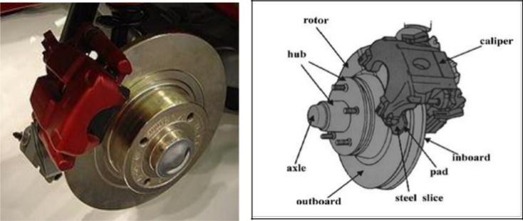
Discbrakeconsistsofasolidirondiscboltedtothewheel hub and a stationary housing referred to as caliper. The caliperislinkedtostationarysectionofthevehicle,usually axlecasingorthestubaxleandismanufacturedwithcasting intwo parts, and with everyphasecontaining a piston. In between every piston and the disc, there is a friction pad held in role with the aid of keeping pins or spring plates. Passagesaredrilledinthecaliperforthefluidtoenterorgo awaythehousingwhichisadditionallyrelatedtosomeother one for bleeding. Each cylinder consists of rubber-sealing ringbetweenthecylinderandpiston.Aschematicsketchof discbrakeisasprovenunderindetermine1.2.1
DiscbrakesaremostfamousinMountainbicycle.Thedisc
brakeperformsveryvitalpositioninbraking.Thenon-stop structural and thermal hundreds from brake pads due to brakingmotionleadtofailureinthepresentformatofdisc.
Discbrakeisthemostimperativegadgetinanyvehicle.
Brakingleadstothefailureofdisc.
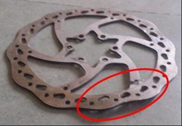
The failure takes place broadly speaking due to the fact crackingandwarpingofthediscclosetoimperativeregions.
2.1 Objectives
disc
Thefailureofthedisccanbepreventedbyusingalteringthe diagramofthediscbrake.Thealternatelayoutchoiceoffers thepowerandstiffnesstothediscbrake.Thegreaterthing ofprotectionischosentolimittheprobabilitiesoffailurein thediscbrake.
•Aimistographandboostthediscbrakeforbicyclewhich sustains the structural load appearing on brake disc all throughmotionofbraking.
• Compare the energy of two exceptional designs of disc brakewithcurrentdiscbrake.
•Thediscbrakewithgreaterpowerofdiagramischosenfor thediscbrakeapplication.
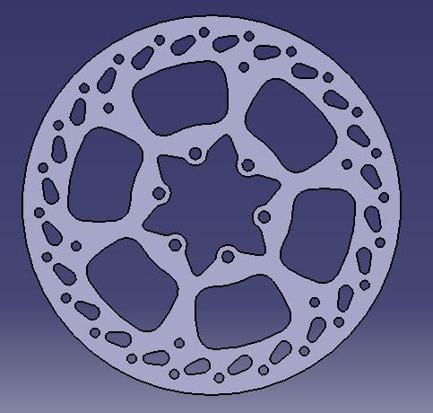
•ExistingsketchofdiscbrakeismodeledinCATIA.
•ThestructuralevaluationiscarriedoutinANSYS.
2.2 Conclusion Drawn From Literature Review
Theresearcheshavebeencarriedouttodiagramtheviable andfeehighqualitydiscbrakestructuresfortheexceptional applications.Someresearchershaveresearchtheimpactof alternate of fabric from forged iron to stainless steel, aluminiumandalloys.Recentlookuphasbeencarriedouton composite fabric to distribute warmth to surrounding environment.Thecompositesubstancesareappropriatefor thermal and structural performances. The Vibration evaluationisadditionallycarriedouttodecidethevibration traits of disc brake system. As per research, the plan enchancment can be the viable choice for the disc brake system.
3.MATERIAL PROPERTIES AND ANALYTICAL CALCULATIONS
3.1 Material Properties
Material property is an intensive, regularly a quantitative property,withaunitthatisusedasmeasureofthecostto
examine the benefits of one cloth versus every other to resourcesubstancesselection.
Materialpropertymayadditionallybeasteadyorafeature of one or extra unbiased variables, such as temperature. Theyregularlyrangetosomedegree,inaccordancetothe pathintheclothinwhichtheyaremeasured;acircumstance referredtoasanisotropy.
3.2 Grey Cast Iron
Silicon is integral to make gray forged iron as hostile to white solid iron. The carbide of iron turns into unstable whensiliconisalloyedwithferriteandcarbonatround2%. Siliconreasonsthecarbonunexpectedlytocomeoutofthe answerasgraphite,leavingamatrixofenormouslypure,and tender iron. There will be excessive activation power for increase when vulnerable bonding between planes of graphite lead presents, which end result in skinny and spherical flakes. This shape has quite a few beneficial properties.
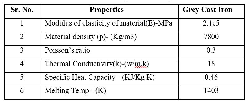
Table 3.1.1.1: Properties of Grey Cast Iron
3.3 Analytical Calculations
3.3.1 Disc Brake Standards
Rotordiscdimension=160mm=0.16m
Rotordiscmaterial=GreyCastIron
Padbrakearea=500mm2(500×10-6 m)
Padbrakematerial=Asbestos
Coefficientoffriction(Wet)=0.08

Coefficientoffriction(Dry)=0.2
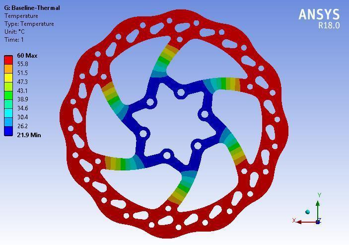
Maximumtemperature=60ºC
Maximumpressure=1MPa(106 Pa)
4. FINITE ELEMENT ANALYSIS
Finite Element Method is a numerical process for fixing continuum mechanics of hassle with accuracy proper to engineers. Finite Element Method is a mathematical modelling device involving discretization of a non-stop
domain?Usingbuilding-blockentitiesknownasfinitefactors relatedtoeverydifferentbymeansofnodesforassoonas and second transfer. This technique consists of Finite ElementModelingandFiniteElementAnalysis
4.1 Temperature distribution in baseline disc-1
distribution in baseline disc-1
The Temperature distribution inside the baseline disc is showninFigure4.2.6.1.Theoutputfromthermalanalysisis provided as input to structural analysis to determine the strengthofthedisc.
4.2 Post-processing of Structural Analysis

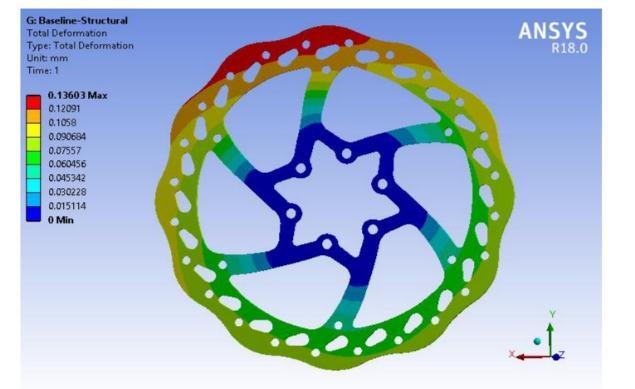
ThedisplacementcontourplotisasshowninbelowFigure 4.3.6.1.
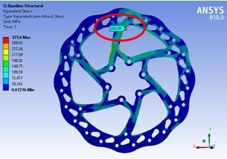
The maximum equivalent stress observed in the baseline disc-1is200MPa.
Theyieldstrengthofthematerialis220MPa.Accordingto theresults,thevon-Misesstress200MPaislessbutnearer totheyieldstrengthofthematerial.Thesuddenorimpact brakingactioncancausethefailureofthediscatweakest crosssectionalareaofthedisc.TheFieldfailureofthediscis causedduetosuddenanddynamicloadactingonthedisc. Thesamelocationofthefailureisdetectedinfiniteelement analysis study which is shown in the Figure 4.3.6.2. The safetyfactor1.1forthebaselinemodelisnearertothevalue 1.
4.3 Alternate Design Proposals
Afterinvestigationoffailureinthebaselinedisc,twodesign proposalspreparedasshownbelowintheFigure4.4.1and 4.4.2thenperformedthethermalandstressanalysis.
Themaximumdisplacementshownbythebaseline(disc-1) designis0.136mm.
4.3.1 Thermal Analysis of Proposed Design
4.3.2
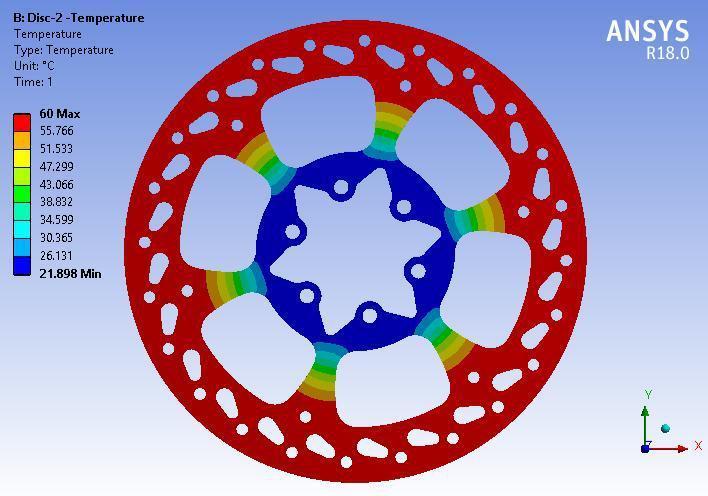
The maximum temperature observed in the proposeddisc-2designis60°C.
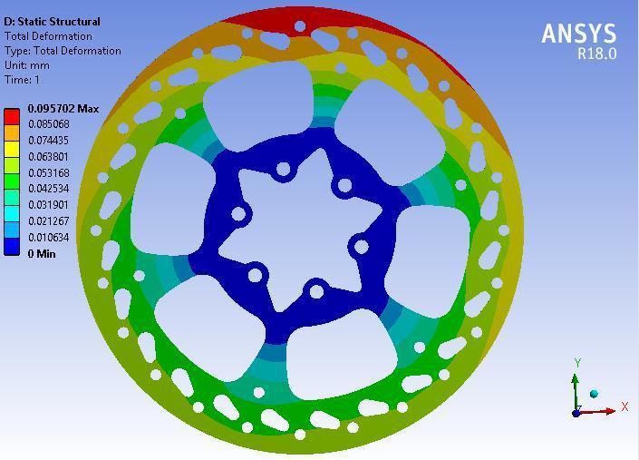
Thetotaldeformationandstressplotsareshownin belowFigures4.4.2.1to4.4.2.4fortheproposeddisc designs.
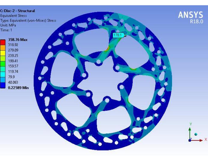
Thevon-misesstressofproposeddisc-2
is178 MPa.
Themaximumequivalentstressobservedintheproposed disc2is178MPa.Theyieldstrengthofthematerialis220 MPa.Accordingtoresults,thevon-Misesstress178MPais less than yield strength of the material. The safety factor observed is 1.24 for the disc 2 which is higher than the baselinemodel.

4.4
Itisfoundfromtheoutcomesthat,Maximumstressesare developedinthebaselinediscandexactlyfitswiththearea failure.Aevaluationofmostwholedeformationandequal stressvaluesforbaselinesketchandsubsequentmodified designsofthediscarecalculated.Followingdeskindicates assessmentbetweenexceptionaldesignsofdiscthruFEA.
The maximum displacement shown by the disc brake for disc-2is0.0957mm.
Astressesintheproposeddisc-2isminimumascompared tothestressesinbaselinedisc
5. EXPERIMENTAL VALIDATION
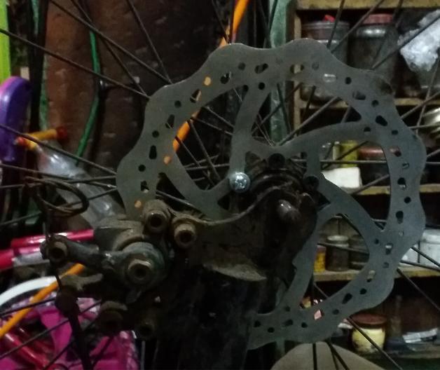
A test rig is developed at a Laboratory for the disc brake experimentation. The test rig is used to take a look at the electricityofthemanufacturedbaselinediscandmodified disctwographinthedynamicloadingcondition.

5.1 Experimental Equipments
Load frame: Twostrongsupportsforthemachine
Load cell:Forcetransducerusedformeasuringtheloads
Output device: Machine have computer interface to for resultinterpretationandanalysis.Oldermachineshavedial anddigitaldisplays.
Conditioning:Thetestrigisplacedinnormaltemperature of230C

Test Fixtures:Testrigisinsertedintothe20mmx20mm holepreparedinthegroundfloor.
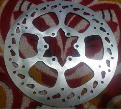
Strain Gauge: To measure the strain values of the test specimenforappliedload.
The stress vs. stress values are recorded via stress gauge meter.
The2ndspecimeni.e.disctwoistakenfortheexperiment. Theidenticalbrakingloadhasbeenutilizedonthedisctwo The stress and stress values are recorded. The load vs. deflectioncurveisadditionallyrecorded.
Observed the disasters in the specimen if any, and the evaluationbetweenbaselineandmodifiedmodelhavebeen recordedinthedeskbelow.
5.2 Experimental Procedure
A take a look at specimen with baseline and optimized fashionsaretakenfortheExperiment.
Baseline specimen positioned internal the fixtures and extensometer.
Appliedthestressgaugestoreportthestressandstressin thespecimen.
Rotated the wheel with 20 Km/hr velocity comparable to mostpaceofmountainBicycle.
Appliedthesurprisingbrakesbywayoftransferringlevers tocharacterizethedynamicconditions.
The exchange in size of the specimen is recorded via the extensometer.
The braking load vs. deflection curve is additionally recorded.
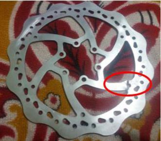
Failureisobservedduringexperimentaltestofbaselinedisc atthesamelocationwherethefieldfailurehastakenplace whichishighlightedintheabovefigure5.2.1
Thereisnofailureobservedintheproposeddisc-2design duringexperimentaltest
5.3 Experimental Results Table 5.3.1: Experimental results
6. RESULTS AND DISCUSSION
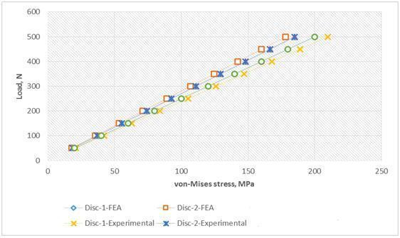
Itisobservedfromtheresultsthat,maximumstressesare developed at inner rib of the disc brake. The maximum deformation in baseline disc is observed up to 0.136 mm. Thevon-Misesstressinthediscforthemaximumloadis200 MPa. The total weight of the baseline disc is 0.1433 kg. Therefore,thevon-misesstressinthebaselinedisc1isless thanyieldstrengthofthematerial.But,thevalueisobserved neartheyieldstrengthlimitofmaterial(Yieldstrengthlimit =220MPa).Therefore,therearechancesoffailureofdisc1 becauseofimpactload/Suddenbrakingaction.
Themaximumdeformationindisc2isobservedupto0.095 mm.Thevon-Misesstressinthediscforthemaximumload of500Nis178MPa.ThetotalweightoftheDisc2is0.1658 kg. Therefore, the von-mises stress in the disc 2 is below theiryieldstrengthofthematerialandthevalueisobserved below the yield limit of material (Yield limit = 220MPa). Therefore,thedesignofdiscissafe.
Graph 6.2: Load Vs Stress (FEA and Experimental comparison)
7. CONCLUSION
Thecomparativefindoutaboutiscarriedoutwiththethree oneofakinddesignsofthediscbrakeandhasreachedatthe followingconclusion:
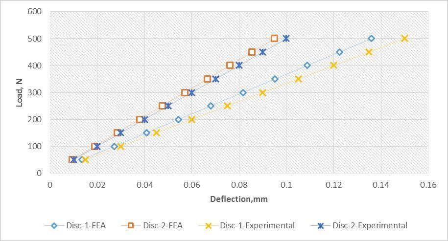
Thedeflectioninmodifiedformatofdisc-2isminimalthan thatofbaselinedesign.
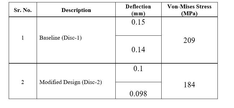

Thevon-Misesstressinthediscbrakelayouttwoisminimal asincontrasttobaselinedesign.
Themassofthediscsketchtwois10%greaterthanbaseline layoutduetoexpandinthestiffness.
Thus,modifiedsketchwithdisc-2ismostappropriateand possible for the contemporary utility from plan and manufacturingperspective.
REFERENCES
[1] Anderson A. E. And Knapp R. A., Hot Spotting in Automotive Friction System Wear, vol. 135, page 319-337,(1990).
[2] Barber J. R., Contact Problems Involving a Cooled Punch, J. Elasticity, vol. 8, page 409-423, (1978).
[3] Brilla J., Laplace Transform and New Mathematical Theory of Visco elasticity, vol. 32, page187-195,(1997).
Graph 6.1: Load Vs Deflection (FEA and Experimental comparison)
The deflection values against applied load for FEA and Experimentalmethodsshowthecorrelationbetweenboth methods, since there is less than 10% variation observed betweenFEAandExperimentalmethods.
[4] Burton R. A., Thermal Deformation in FrictionallyHeatedContact,Wear,vol.59,page120,(1980).
[5] Flouet A. And Dubourg M.C., Non axis symmetric effect three dimensional Analyses of a Brake, ASME J. Tribology, vol. 116, page 401-407. (1994).
[6] KennedyF.E.,et.al.,ImprovedTechniques for Finite Element Analysis of Sliding Surface Temperatures. Westbury House page 138-150, (1984).
[7] ManjunathT.V.AndDr.SureshP.M.,(2013 Dec),StructuralandThermalAnalysisofRotorDisc of Disc Brake,[Online].Available: https://www.ijirset.com/upload/2013/december/ 51A_Structural.pdf
[8] PigozziG.AndCerettoE.,CombinedThermal and Mechanical Analysis of Truck Brakes, Conference Innovation and Reliability in Automotive Design and Testing, Vol. 2, page 921933,(1992).
[9] Sowjanya K. And Suresh S., (2013 Jul), Structural Analysis of Disc Brake Rotor,[Online].http://ijcttjournal.org/Volume4/issu e-7/IJCTT-V4I7P159.pdf

[10] Tsinopoulos S. V., et. al., An Advanced Boundary Element/Fast Fourier Transform Axis symmetricFormulationforAcousticRadiationand Wave Scattering Problems, vol. 105, page 15171526,(1999).
[11] Venkatraman R, et. al. (2015 Mar), Design andAnalysisofDiscBrakeRotor.[Online].Available: https://www.researchgate.net/publication/295980 262_Design_and_Analysis_of_Disc_Brake_Rotor.pdf
[12] WangH.C.AndBanerjeeP.K.,Generalized Axis symmetric elastodynamic Analysis by BoundaryElementMethod,vol.30,page115-131, (1990).
[13] https://en.wikipedia.org/wiki/Disc_brake
