Role of 3D Printer in Additive Manufacturing
Dept of Mechanical Engineering.
1Lecturer. Dept of Mechanical Engineering.
2,3,4Final Year Diploma Student of Mechanical Engineering.
5Final Year Graduate Student of Mechanical Engineering.
6Third Year Graduate Student of Mechanical Engineering.
1,2,3,4A.G. Patil Polytechnic Institute Solapur, Maharashtra, India
5Nutan College of Engineering and Research, Pune, Maharashtra, India.
6Bharat Ratna Indira Gandhi college of engineering, Solapur, Maharashtra, India. ***
Abstract - - Additive Manufacturing is the process in which the material is added layer by layer to make the final prototype/product. Additive manufacturing (AM) is the latest technology that could improve the manufacturing process by building up thin layers of materials from digitized threedimensional (3D) designs virtually constructed using advanced CAD software. This technique offers the creation of new types of objects with unique material properties. A massive media and public interest in the technology has led to the latest state of the art of exploring the technology for applications beyond the scope of the traditional engineering industry.
Key Words: Additivemanufacturingprocesses,prototype, 3D printing, rapid manufacturing, Material extrusion, STL file,slicing.
1.INTRODUCTION ADDITIVE MANUFACTURING

Inadditivemanufacturing,anobjectismadebybuildingit layer by layer, which is different from subtractive manufacturing,whichinvolvescuttingawayasolidblockof materialtocreateafinishedproduct.Althoughtechnically, thisprocesscanbeusedtocreatevarioustypesofproducts, suchasmolds,itismainlyreferredtoas3-Dprinting.During the 1980s, additive manufacturing was used to develop prototypeproducts,whichwereusuallynotfunctional.This processwasreferredtoasrapidprototyping,asitallowed individualstocreateascaleversionoftheirfinishedproduct injustacoupleofhours.Theriseofadditivemanufacturing ledtothedevelopmentofrapidtooling,whichenablesthe creation of molds for final products. By the 2000s, it had becomewidelyusedtocreatefunctionalgoods.Someofthe companiesthathavestartedusingthistechnologyinclude GeneralElectricandBoeing.
1.1 Types of Additive Manufacturing Processes
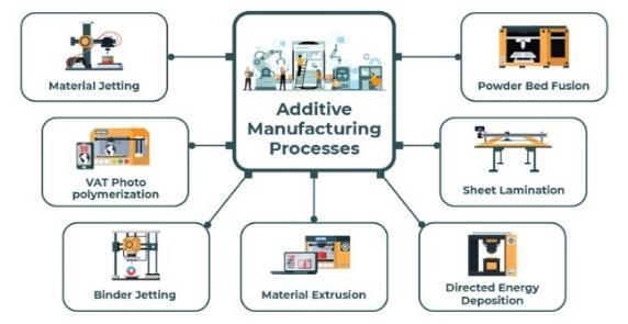

1. BinderJetting.
2. DirectedEnergyDeposition(DED)
3. MaterialExtrusion.
4. PowderBedFusion(PBF)
5. SheetLamination.
6. VatPolymerization.
7. MaterialJetting.
2. INTRODUCTION TO MATERIAL EXTRUSION
Usingtheadditivemanufacturing(AM)techniqueofmaterial extrusion, a spool of material (typically thermoplastic polymer)isdriventhroughaheatednozzleandselectively positioned layer by layer to create a 3D object. Fused filament fabrication (FFF) and fused deposition modelling (FDM) are two examples of material extrusion processes. Material extrusion is frequently slower and less accurate than other types of additive manufacturing. However, the technology for material extrusion and the relevant raw materials, including nylon and ABS plastic, are readily accessibleandinexpensive.Asaresult,materialextrusionis the approach that home 3D printing hobbyists most frequentlyemploy.Inmanufacturingandindustrialsettings, material extrusion is widely used to produce inexpensive, rapidprototypesforvariousversionsofthesamething.
Supportscouldbeneeded.
Z-axiscomponentstrengthissubpar(perpendicular tobuildplatform)
Print time is increased by greater area and finer resolution.

Pronetodelaminationandotherproblemscaused bytemperaturefluctuations
Hazardousprintmedia
3. ACTUAL WORKING
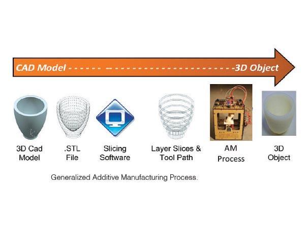
Intheprocessofadditivemanufacturing,a3Dpictureisfirst createdusingsoftwarelikeCAD,Catia,etc.Afterthat,thisfile istransformedintoanSTLfile.Stereolithographyisreferred to as an STL file or Standard Triangle Language. A set of connected triangles 3D models or an object's surface geometry is described in each file. More triangles are employed, and the resolution is higher as the design becomes more complicated. We enter the image into the slicer after obtaining the surface geometry. Slicer is a gobetweenfora3DCADmodelanda3Dprinter.
Advantages
Awideselectionofprintmedia.
Astraightforwardprintingprocedure.
A straightforward and user-friendly technique of switchingmaterials.
Lowstartupandrecurringcosts.
An equivalent decrease in print time for tiny and thinitems.
A+/-0.1(+/-0.005′′)toleranceforprintingerrors.
Nosupervisionisrequired.
TheequipmentissmallerthanotherAMprocesses.
Theprocesstemperatureiscomparativelylow.
Disadvantages
Apparentlayerlines
Iftheextrusionheadstopsmoving,thematerialwill bump.
The3DCADmodelwillbestoredinoneofthefileformats, typicallySTL.Aslicerdoeswhatitsnameimplies:itslices the 3D model. It specifies the tool path that the printer shouldusetoproperlyprinteachlayeroftheslicedmodel and how each layer should be produced. A slicer is a componentof3Dprintingsoftwarethatconnectsvirtualand physicalmodels.ThedigitalmodelisconvertedintoG-code, theprintinginstructions,viathe3Dprintingslicersoftware. The printer receives these instructions and, in response, untiltheobjectisfinished.
Fig – 4: WorkingProcess
4. INTRODUCTION TO MACHINE
4.1 What is 3D Printing?
Additivemanufacturing,sometimesknownas3Dprinting, creates solid, three-dimensional objects from digital files. 3D-printed things are made possible through additive manufacturingtechnology.Anadditiveprocessproducesan object by gradually adding components until the desired
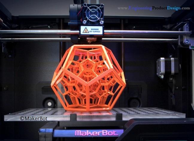
resultisachieved.Across-sectionoftheobjectthathasbeen thinly cut can be imagined in each of these layers. For example,amillingmachinecanbeusedtohollowoutorcut outapieceofmetalorplastic.Subtractivemanufacturingis thealternativetoadditivemanufacturing Whencompared toconventionalproductiontechniques,3Dprintingusesless materialtocreatecomplicateddesigns.
4.3 3D Software
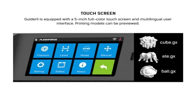
Softwareinstrumentscomeinawidevariety.rangingfrom open source to commercial quality. On our page for 3D software, we have a summary produced. Tinker pad is a commonplacewhereweadvisebeginnerstostart.Youdon't need to install Tinker Cad on your computer because it is freeandoperatesinyourbrowser.TinkerCadfeaturesbuiltinfunctionalitytoexportyourmodelasaprintableformat, suchasanSTLor.OBJ,anditalsogivesintroductorylessons. Thefollowingstepistogettheprintablefilereadyforyour 3Dprinter.Werefertothisasslicing.
Slicing: Fromprintablefileto3DPrinter
With the use of slicing software, a 3D model is basically divided into hundreds or thousands of layers. Your file is readytobesenttoyour3Dprinterafterithasbeensliced. Through USB, SD, or Wi-Fi, you can send the file to your printer.Nowthatithasbeendividedintolayers,yourfileis preparedfor3Dprinting.
5. MATERIALS
ABS (acrylonitrile butadiene styrene)
Toughanddurable
Heatandimpactresistant
Requiresaheatedbedtoprint
Requiresventilation

PLA (polylactic acid)
TheeasiestFDMmaterialstoprint
Rigid,strong,butbrittle
Lessresistanttoheatandchemicals
Biodegradable
Odorless
PETG (polyethylene terephthalate glycol)
Able to print at lower temperatures for quicker output
Humidityandchemicalresistant\
HighTransparency
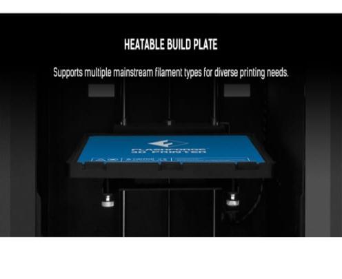
HeatableBuildPlate
4.2 How Does 3D Printing Work?
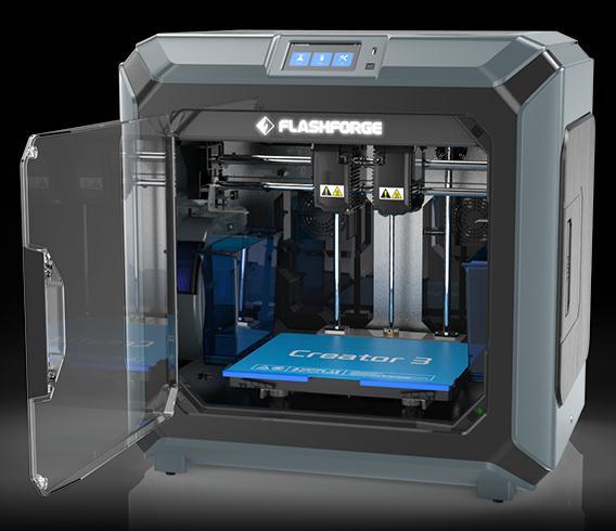
A3Dmodeliswhereitallbegins.
A3Dmodelcanbedownloadedordevelopedtotally fromscratch.
Canbefoodsafe
Nylon
Strong,durable,andlightweight
Toughandpartiallyflexible
Heatandimpactresistant
VerycomplextoprintonFDM
TPU (thermoplastic polyurethane)
Flexibleandstretchable
Impactresistant

Excellentvibrationdampening
PVA (polyvinyl alcohol)
Solublesupportmaterial
Dissolvesinwater
HIPS (high impact polystyrene)
ThemosttypicalsolublesupportmaterialforABS
Dissolvesinchemicallimonene
Composites (carbon fiber, kevlar, fiberglass)
Rigid,strong,orextremelytough
Only a few pricey industrial FDM 3D printers are compatible.
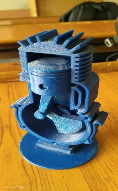
Engine is the machine used for converting any form of energy into motion and mechanical force. The engine has connectingrod,piston,crankshaft,cylinder,flywheel,spark plug, inlet and outlet ports. 2 stroke engine has 4 strokes knownasSuction,Compression,Expansion,Exhaust.Itisthe enginewhichcompletesitscyclein2revolutionandhasits1 stroke of 90 degree. A two-stroke (or two-stroke cycle) engineisatypeofinternalcombustionenginethatperforms twopistonstrokes(upanddownmovements)throughouta powercycle,whichisfinishedinonecrankshaftrevolution. Apowercycleinafour-strokeengineinvolvesfourpiston strokesoverthecourseoftwocrankshaftrevolutions.Ina two-strokeengine,theintakeandexhaust(orscavenging) activities happen simultaneously at the end of the combustionstrokeandthestartofthecompressionstroke. Duetothepowerbeingaccessibleinaconstrainedrangeof rotational speeds known as the power band, two-stroke enginesfrequentlyhaveahighpower-to-weightratio.Twostroke engineshave fewer moving componentsthan fourstrokeengines.
Aerospace
Medical
Transportation
Energy
Consumable Products
A centrifugal pumps impeller is a revolving part that accelerates fluid away from its center of rotation, transferringenergyfromthepump'smotortothefluidbeing pumped.
Apartofpumporcompressorknownasanimpellerrotates quickly and serves as a propeller to increase a fluid’s pressure and flow rate. Impellers are made of plastic and othermetals,suchassteel,ironandbronze.Becauseofthe fluid’senergytransferfromtheimpellerasittravelsthrough thepump,thefluidsvelocityraisesatthedischargeoutlet.
Therearethreetypesofimpellers:
Openimpeller
Closedimpeller
Semi-openimpeller
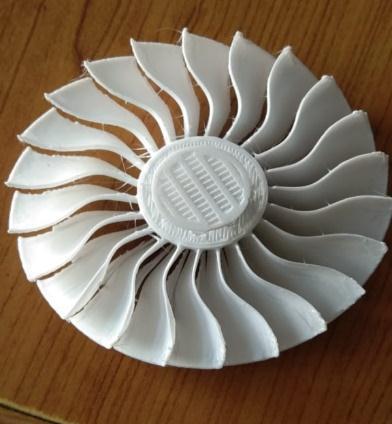
Therotationalspeedofanimpelleriscommonlyexpressed inrevolutionsperminute(rpm).Afluid(aliquidoragas)is drivendownatubeatanincreasedpressure,andanimpeller increases the velocity of the fluid. Fluids and gases are frequently transported over great distances in pipes by pumpsandcompressorsthatincludeimpellers.
thelayers.IfGcodesarenotgeneratedproperlytheproblem mayoccurinprinting.
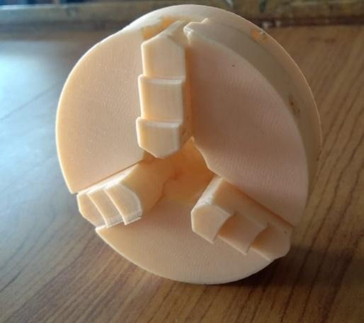
Aspecifictypeofclampknownasa"chuck"ismadetohold radiallysymmetricalitems,mostnotablycylinders.Achuck holdstherevolvingtoolinadrill,mill,andtransmission;ina lathe,itholdstherotatingworkpiece.
Jaws are frequently used by chucks to grip the tool or workpiece.Thejaws,whichareoftenreferredtoas"dogs," are typically organized in a radially symmetrical arrangementsimilartoastar'spoints.Somejawedchucks, whichofferconvenienceatthesacrificeofgrippingforce,can betightenedorloosenedbyhandforcealone.Certainjawed chucks,however,mayrequiretheuseofawrench-liketool calledachuckkey.Certainlathes'chucksincludejawsthat canmoveindependently,enablingthemtograspobjectsof odd shapes. More jaws, more jaws, or quick-release mechanismsareexamplesofmoresophisticateddesigns.
Collets,whichareflexiblecollarsorsleevesthatwrapsnugly around the tool or workpiece and grab it when squeezed, may be used in place of jaws in a chuck instead of magnetism,vacuum,orcollets.
8. FAILURE
Whenwewerepreparingtheassemblyof2strokeICengine wefailedmanytimes.Asitisasectionalviewwhileprinting it needs the support. While making layer, if the circle is vertical,itneedsthesupport,andifitishorizontal,itdoesn't needsupport.
Whileprintingcylinderverticallythesupportneededtoit, becauseofthatsupportthereisachancetogetgapbetween
9. CONCLUSION
One of the most modern technology in manufacturing by which the product is built layer by layer. While studying aboutthe3Dprinterwemadesomeoftheprototypeslike2 stroke engine, Impeller and 3 jaw chuck. By making the prototypes we also come to know about the working of 2 stroke engine and mechanism of 3 jaw chuck. We are fortunatetohavethe3Dprinteravailableinourcollege.As there was ANNUM NATIONAL LEVEL PAPER PRESENTATIONcompetitionbecauseof3Dprinterwehave cometoknowtheactual3Dprintingprocess.Astheother colleges students had no chance to recognize or to get chance to work on it. We are mor fortunate to have the actual3Dprinterinourcollege.
REFERENCES
[1] https://www.flashforge.com/product-detail/flashforgecreator-3-fdm-3d-printer
[2] https://www.twi-global.com/technicalknowledge/faqs/what-is-additive-manufacturing
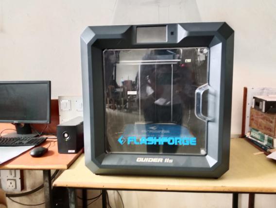
[3] https://www.3way.si/3d-printers/flashforge/guideriis/?lang=en
[4] https://www.twi-global.com/technicalknowledge/faqs/what-is-material-extrusion
[5] https://www.plm.automation.siemens.com/global/en/o ur-story/glossary/material-extrusion/53981

BIOGRAPHIES
Mrs. Devanshi A. Jhaveri, Dept. of MechanicalEngineering,A.G.Patil Polytechnic Institute, Solapur, Maharashtra,India.


AratiR.Bharale,Diplomastudent, Dept.ofMechanicalEngineering,A. G. Patil Polytechnic Institute, Solapur,Maharashtra,India.
Aman D. Mulla, Diploma student, Dept.ofMechanicalEngineering,A G Patil Polytechnic Institute, Solapur,Maharashtra,India


Akash M Chougule, Diploma student, Dept. of Mechanical Engineering,A.G.PatilPolytechnic Institute, Solapur, Maharashtra, India.
Shruti D. Waghmare, Undergraduate student, Dept. of Mechanical Engineering, Nutan College of Engineering and Research, Pune, Maharashtra, India.

Manthan A Bansode, Undergraduate student, Dept. of Mechanical Engineering, Bharat Ratna Indira Gandhi College of Engineering,Solapur,Maharashtra, India

