CFD modelling calculation and simulation of bus

2AssociateProfessor, Swami Vivekanand College of Engineering

3 AssociateProfessor, Swami Vivekanand College of Engineering
4AssistantProfessor, Swami Vivekanand College of Engineering
Abstract - The study of his project is to be concentrated on CFD analysis of bus interior for optimization of thermal comfort for the entire passenger in a bus that is available in market. For the upcoming market the need of greener city transportation is on the peak the busses will play as the life line of transportation and main challenges of buses is to optimize the design for the minimum consumption of power and maintain safety and comfort for the passenger. This study will works in this direction the aim of the study is to formulate CFD analysis using CFD tool to optimize the passenger comfort in the bus the main objective to work within a given specifications of dimensions, electrical power requirement of bus AC, and other system to be fulfilled under norms issued by authorities and doing changes to maximize the effectiveness of AC for individual passengers.
Key Words: CFD,Fluent,polyhedralmesh
1. INTRODUCTION
Computationalfluiddynamics(CFD)isatechniqueoffluid mechanicsthat usesmathematical numerical analysisand applieddatawithitsphysicalpropertiessuchaspressure, velocity, temperature, density and viscosityto solve and analyzeproblemsthatinvolvefluidflows
1.1CFDsimulation
The city public transportation bus has the purpose of transporting numerous people and is considered a sustainablemeansoftransportation.Theproblemsthatare faced by the electrical vehicles are the overheating of passenger cabin due to lack of proper ventilations in hot sunnydaysandquickdrainingofbatteryordecreasingthe efficiency of vehicle. The paper is focused on increasing effectivenessofACconsideringfollowingparameters.
AC performance depends on geometry & operating parameter
1.2Geometricalparametersandoperatingparameters
⮚ Geometrical parameter
1. Ductshapeandsize
2. Cabinsize
3. Windowsarea
4. Insulatingpropertiesofbusstructure
⮚ Operatingparameter
1. Ambienttemperature
2. Flow velocity of cooling spots in duct above passenger
3. Busoperatingvelocityandrelativepositionofsun
4. Enginespeedandinternalheatgeneration
2. MESH SIZE DETERMINATION
2.1Methodologytodeterminemeshsize
Mesh size for CFD flow problem depends upon the turbulencemodelofCFDthathastobeuse,velocityofflow inmodel anduseof wall function.For gettingsomeinitial dataofallthiswearerunningsimulationwithcoursemesh.
2.2InitialCFDsimulation
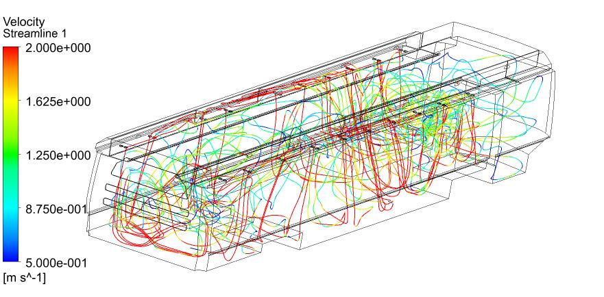
Meshsize for initial simulationis 50mm issolvedinitially withboundaryconditionsshowninfig.1theinitialResults shownbelow
2.3DataandcalculationsfromdataobtainedbyinitialCFD simulation
Table -1:Velocityobtainedbyinitialrunofbus
2.3.1Turbulencecalculation
Velocity =40m/sec
Characteristiclength =1m
Kinematicviscosityofair =1.4207E-5m2/sec
Using

Reynoldsnumber=ρVl/µ
Where
V=Velocityofthefluid
l=thecharacteristicslength
µ/ρ=Kinematicviscosity
Reynoldsnumber=2815513
Since the Reynolds number is high thus flow can be consideredasreliableforfree-shearflowsthusk-ϵrealizable turbulencemodelwillbeappropriatefortheproblem.
Generally when you building grid for RANS model of kepsilonthetargetvalueofy+shouldbebetween30and300. They+dependsonfrictionvelocityu*=sqrt(Tw/rho)where Twiswallshearstress,elementdistancetothenearestwall andlocalkinematicviscosity.
Forthisproblemwearetargetingy+valueof100aswall shearisnotthatimportantinourproblem
2.3.2Calculationforfirstcellheightand2Dmeshsize
Table -2:firstcellheightand2Delementssizecalculated values
2. CFD SIMULATION

CONSIDERATIONS
Forsimulationweusedabusthatiscommerciallyavailable whosegeometryisdefinedbelow.
Sinceallowedaspectratiois10to15infirstprismlayer thus2Dmeshsizewillbeequalto10xoffirstcellthickness.
Fig -2:BoundaryconditionsforCFDofbus
Considering operating condition of bus in warm environment with direct application of sunlight and full capacity AC application the following parameters can be considered.
2.1
Table -3:Boundaryconditions
ACcoldairflowinductcalculations
Inputs
Heatrejectionrate(watt)=10.34ton×3500=36389J/sec


Massflowrateofair =densityofair×Volumeflowrate
=1.225kg/m3×110m3/min
=134.78kg/min= 2.24583 kg/s
Heatrejectionbyair =massflow×specificheatcapacity ×temperaturedifference

36389J/sec=2.24583kg/s×1006.43J/kg-˚C×temperature difference
Temperaturedifference =16.1˚C
Coldairtemperature = ambient temperatureTemperaturedifference
Cold air temperature = 34 ˚C - 16.1 ˚C = 17.9 ˚C
For modelling we uses hypermesh as preprocessor and created 2D shell mesh and for making polyhedral cells we usedfluent.


FromtheContouronecaneasilyidentifiestheregionwhichis hotterlikeinmiddleofbusnearwindowswecanidentifies some discomfort in passenger. The same thing can be confirms if we plot horizontal sections of contour shown below.


From the above contour one can easily finds the middle portion has higher temperature and low air velocity thus passengerinthemiddlewillfeellesscomfortable.
3. CONCLUSIONS
• Thetemperaturearoundtheoccupantseemstobe ok,somehowtherearecertainregionswarmernear the windows and temperature aroundthe middle regionisnotuniformlydistributed.
• Airvelocityinthemiddleofbusisquitelow
• Modificationinducttoprovidehigherflowofairin middlecansolvetheproblem
ACKNOWLEDGEMENT
Dr. Pradeep kr Patil5
5Professor, Swami Vivekanand College of Engineering For givinghugesupportinresearchanddevelopmentofmodel.
REFERENCES
[1] Parametric Investigation Using Computational Fluid Dynamics of the HVAC Air Distribution in a Railway Vehicle for Representative Weather and Operating Conditions PUBLISED IN Energies2017,10(8), 1074;https://doi.org/10.3390/en10081074
[2] Numerical Simulation of the Thermal Comfort in a ModelofaPassengerCarCabin,January2016
[3] Notes on Numerical Fluid Mechanics and MultidisciplinaryDesign132
[4] On the Possibility of CFD Modeling of the Indoor Environment in a Vehicle, Sustainable Solutions for Energy and Environment, EENVIRO 2016, 26-28 October2016,Bucharest,Romania
[5] Nitin S. Gokhale, Sanjay S. Despande, Dr. Anand N. Thite, "Practical Finite Element Analysis", Finite To Infinite,India,2007.
[6] 2-D CFD analysis of passenger compartment for thermalcomfortandventilation;InternationalJournal ofEngineeringandManufacturingScience.ISSN22493115Vol.7,No.1(2017)
[7] EvaluationofCabinComfortinAirConditionedBuses UsingCFD;2014-01-0699
[8] Cfd Analysis Of Air Flow And Temperature
DistributionInAnAirConditionedCar;International Refereed Journal ofEngineeringandScience(IRJES)

ISSN(Online)2319-183X,(Print)2319-1821Volume 2,Issue4
[1] Numerical Simulation of the Flow in a Passenger CompartmentandEvaluationoftheThermalComfort oftheOccupants;SAETransactions;Vol.106,Section 6:JOURNALOFPASSENGERCARS:Part1(1997),pp. 806-816(11pages)
[2] Cfd analysis on aerodynamic effects on a passenger car;InternationalResearchJournalofEngineeringand Technology (IRJET) e-ISSN: 2395-0056 Volume: 04 Issue:09|Sep-2017
BIOGRAPHIES
[3] Numerical Study on Human Thermal Comfort in a PassengerTrain;TransactionsoftheKoreanSocietyof AutomotiveEngineers SagarVerma ME Student, Swami Vivekanand College of Engineering
Dr.Rahuljoshi Associate Professor, Swami Vivekanand College of Engineering
Dr.MayankLadha Associate Professor, Swami Vivekanand College of Engineering

Mr.Manojsharma Assistant Professor, Swami Vivekanand College of Engineering


