WEIGHT OPTIMISATION OF COMPOSITE BUMPER BEAM IN COMPACT ELECTRIC CARS
Ms. Shital Potdar1 , Prof. N.
Vivekanandan2 .[1] ME Student, Dept. of Mechanical Engineering, Pimpri Chinchwad College of Engineering, Pune
[2] Professor, Dept. of Mechanical Engineering, Pimpri Chinchwad College of Engineering, Pune

Abstract – A Front Bumper beam is an important automotive component to protect passengers from injury and damage produced by severe collision. Composite materials can be used in Bumper beam to increase the structural performance and providing light weight solutions. Initially we considered 3 shapes of bumper beam i.e., D shape, B shape and C shape. Static Structural analysis was performed on these 3 shapes. The results are analyzed from the aspect of Equivalent stress and Total deformation. Then it is observed that C shape bumper beam gives better best result than other shapes. So, we used C shape bumper for further process. For designing of bumper beam 2 different composite materials are used i.e., jute fiber and synthetic glass fiber. Static structural analysis performed for both the composites. After FEA results, Optimized composite beams manufactured using hand lay-up method. Experimental validation of optimized composite beam was done on Universal Testing Machinebythree-pointbendingtest.
Key Words: Bumper Beam, Composite Material, StructuralAnalysis.
1. INTRODUCTION
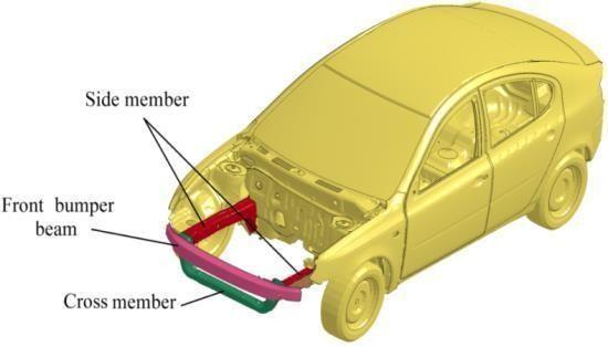
In recent years the auto industries are principally concentrating on electrical cars development. however electrical automotives conjointly needed external body to protect passengers from car accident. And conjointly want BIW systems for assemblies [2]. The Bumper is most vital element and highlighted part in safety. The bumperisgenerallymanufacturedfromsteel
A bumper may be a structurally connected or integrated with the front and rear ends of a motorized vehicle, to soak up the impact in a minor collision, ideally minimizingtherepairprices. theaimof gettinga bumper on your automotive is incredibly specific. many of us suppose that its purpose is to stop or reduce injury severity in a very crash [3]. In fact, bumpers don't seem to be thought of safety options supposed to shield occupants in the slightest degree. The aim of bumper is to scale back or forestall physical harm to the front and rear of vehicles in low-speed crashes. The bumpers are designedto shield thehood, trunk, grill, fuel, exhaustand coolingsystem.
Abumperistypicallymanufacturedfromsteel,Aluminum, etc. It absorbs shocks from automotive accidents. The standardsaysitneedsprotectionwithintheregionsixteen totwentyincheshigherthanthepavedsurface.
As electrical cars are chiefly specialized in the efficiency ofthebatteryanddrivingrange So,scalebacktheburden oftheautomobileisbestplantoextendthepotencyofthe electron volt So, to beat this designated Al and stuff are designatedtodevelopmachinebumper however,focusis on conjointly strength of the bumper Develop differing kindsofformofbumpertoextendtheeffectivenessofthe mostpurposeofbumper
Therearedifferingkindsofstuffonthemarketinmarket and chiefly classified as natural stuff and artificial compositematerials[1].Theseconstituentmaterialshave notably dissimilar chemical or physical properties and are incorporated to form a cloth with properties in contrast to the individual parts. Inside the finished structure, theindividualpartsstayseparateanddistinct, characteristic composites from mixtures and solid solutions. Fiber- reinforced chemical compounds embrace carbon fiber bolstered polymer and glassreinforced plastic If classified by matrix then there are thermoplastic composites, short fiber thermoplastics, long fiber thermoplastics or long fiber- reinforced thermoplastics.
2. LITERATURE SURVEY

The paper [1] proposes Carbon fiber composites have demonstrated to have the option to perform incredibly wellonaccountofa crashandarebeingusedtoproduce committed energy-retaining parts, both in the engine sport world and in developments of aeronautic design While in metallic designs the energy assimilation is achieved by plastic deformity, in composite ones it depends on the material diffuse crack. The plan of composite parts ought to give steady, standard and controlled dispersal of dynamic energy to keep the deceleration level as least as could be expected That is possible solely after nitty gritty insightful, exploratory and numerical examination of the primary crashworthiness. In request to guarantee the driver's securityifthereshouldariseanoccurrenceofhigh-speed crashes, extraordinary effect structures are intended to retain the racecar's motor energy and cutoff the deceleration following up on the humanbody.Incurrent autoturnofevents,toimprovetheircrashworthinessand increment solidness to weight proportion, composite material is presented with the extent of streamlining of carbodyparts.
The paper [2] proposes Application of normal fiber composites will increment in various regions caused by environmental, technical and financial benefits. In any case, their low mechanical properties have restricted their particular application in car primary segments. Hybridizations with different fortifications or matrices can improve mechanical properties of regular fiber composite Also, mathematical optimizations have a critical part in primary strength improvement. This investigation zeroed in on choosing the best geometrical guard pillar idea to fulfill the security boundaries of the characterizeditemplanspecification.
The paper [3] proposes Taylor and Francis bends over backward to guarantee the exactness of all the data (the "Content") contained in the distributions on our foundation Be that as it may, Taylor and Francis, our representatives, and our licensors make no representations or guarantees at all regarding the accuracy, completeness, or appropriateness for any reasonfortheContent.Anyassessmentsandperspectives stated in this distribution are the viewpoints and perspectivesonthecreators,andarenottheperspectives on or supported by Taylor and Francis. The exactness of the Content not be depended upon and should be autonomouslycheckedwithessentialwellspringsofdata Taylor and Francis will not be responsible for any misfortunes, activities, claims, procedures, requests, costs, costs, harms, and different liabilities what severer howsoever caused emerging straightforwardly or by implication regarding, in relation to or emerging out of theutilizationoftheContent.Todiminishfuelutilization
andoutflowsandtohelpimprovevehicle'spresentation,it isimportanttomakevehicleslighter.
The paper [4] proposes the crashworthiness and lightweight necessities in auto industry, composite material shave been acquiring progressively more consideration fortheirhigh explicit strength, highspecific stiffness and high energy retention capacity Guard frameworkisoneofthefundamentaldesignswhichsecure cars from the front and back crashes. It's anything but a powerful method to foster the guard framework utilizing composite materials to meet the accident security and lightweight requests at the same time. Notwithstanding, the application of composite material additionally brings incredible difficulties into the enhancement configuration measure, for example, complex non-direct material conduct,multiworkingconditionsandenormousmeasure of plan factors. In this paper, a construction plan and enhancement strategy are proposed for a business front guardsystemmadeviacarbonfiberwovencomposite
The Paper [5] proposes automotive guard pillar is a significant parttoshield travelerand vehicle from injury and damage actuated by serious breakdown Late examinations showed that froth filled designs have significant advantages in light weight and high energy assimilation Inthis paper,a novel guardshaftfilled with functionally evaluated froth (FGF) is considered here to investigate its crashworthiness. To approve the FGF bumper shaft model, the tests at both segment and full vehiclelevelsareconducted.Parametricstudyshowsthat inclination outstanding boundary m that controls the varietyof frothdensityhascritical impactonguardbar's crashworthiness; and the crashworthiness of FGF-filled bumperbeamisdiscoveredfarsuperiortothatofuniform froth (UF) filled and empty guard bar A FGF-filled guard bar framework was concentrated in this paper, aimed to improve the energy absorption under sway A numerical FGF-filledguardbarmodelwasworkedwithunequivocal finite element code LS- DYNA Parametric examination was directed to explore the impacts of FGF-filled guard shaft boundaries on crashworthiness in correlation with the UF-filled guard beams. It was tracked down that the FGF-filled guard bar permitted absorbing more sway energy than the UF-loaded up with a similar weight Density angle m, thickness range (qf1 and qf2), and dividerthicknesseffectslyaffectEA,SEA,Fmax,andCFE
3. PROBLEM STATEMENT
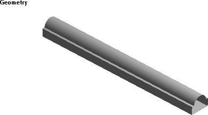
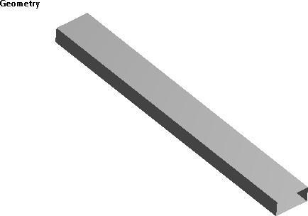
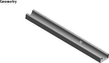
1) To study effect of cross-sectional shapes of structures onelectriccarsbumperbeam.
2) Study ofNaturalandSyntheticcompositefibersused forbumperbeamapplication
4. OBJECTIVES
1) To perform static structural analysis of composite bumperbeaminANSYSWorkbench
2) Manufacturing of optimized composite beam using handlayupMethodology
3) StudyofNatural&Syntheticcompositefibersusedfor bumperbeamapplication
4) Experimentalvalidationofoptimizedcompositebeam withthehelpof3pointbendingtestonUTMMachine
5. METHODOLOGY
Step 1- Initially research paper is studied to find out research gap for project then necessary parameters are studied in detail. After going through these papers, we learnt about reinforcement of composite material bumper beamincompactelectriccars.
Step 2- Research gap is studied to understand new objectivesforproject
Step 3- After deciding the components, the 3D Model and draftingwillbedonewiththehelpofCADsoftware
Step 4- The static structural analysis of the components willbeperformedwiththehelpofANSYStoolpost
Step 5-TheExperimentalTestingwillbecarriedoutusing UTM

Step 6- Comparative analysis between the experimental andanalysisresult
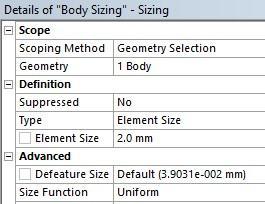
ANSYS Meshing is a general-purpose, intelligent, automated high-performance product It produces the most appropriate mesh for accurate, efficient Multiphysics solutions.
BOUNDRY CONDITION
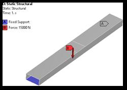
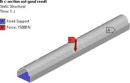
A boundarycondition forthemodel is thatthesetting ofa well-knownvalueforadisplacementoranassociatedload Foraspecificnodeyou'llbeabletoseteithertheloadorthe displacement but not each. The main kinds of loading obtainableinFEAincludeforce,pressureandtemperature Thesemaybeappliedtopoints,surfaces, edges, nodesand componentsorremotelyoffsetfromafeature.Weapplythe 15000 N force on the front bumper as shown in fig. of boundary condition for calculating the maximum deformationandequivalentstress.
RESULTS
Theequivalentstressis29957MPa


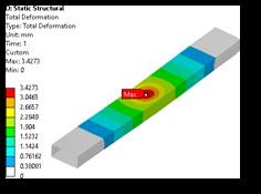
The maximum deformation is 34mm

ANALYSIS OF B SHAPE BUMPER

MESHING
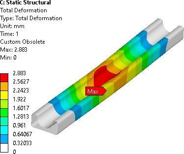
MaximumdeformationwasinducedinBShapeBumperis 2883mm
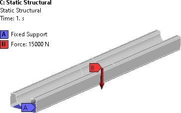
BOUNDARY CONDITION
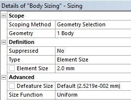
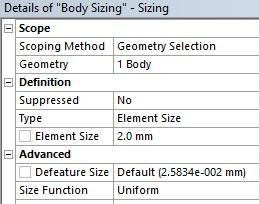
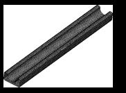
MESHING

RESULTS

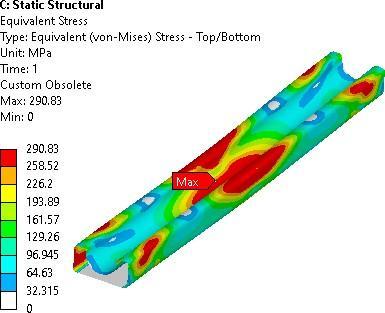
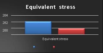
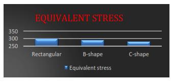
Maximum Equivalent stress was induced in B Shape Bumperis290.83MPa


BOUNDARY CONDITION
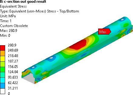
TheequivalentstresswasinducedinCShapeBumper 280.9MPa
COMPARISON OF TOTAL DEFORMATION AND EQUIVALENT STRESS WITH DIFFERENT SHAPES


We notice that C-shape bumper beam gives better result than other shapes. So, we use C-shape bumper beam for furtherprocess.
MaximumdeformationwasinducedinCShapeBumper is12mm
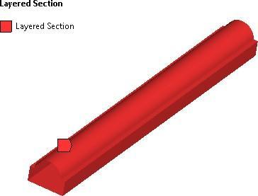
BOUNDARY
ANALYSIS

BOUNDARY CONDITION

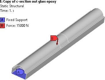
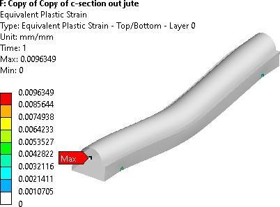
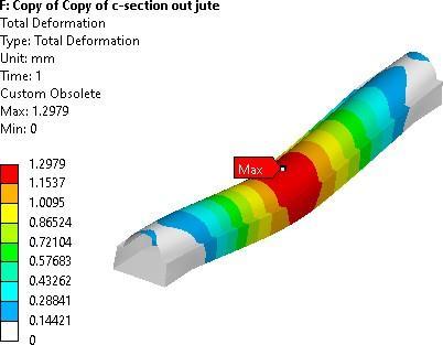
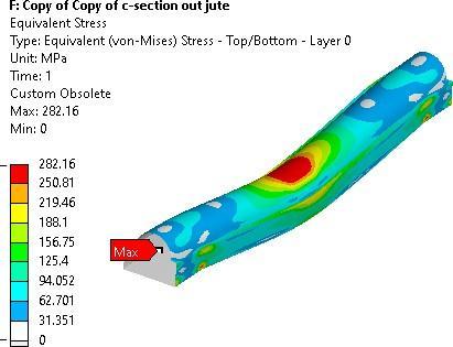
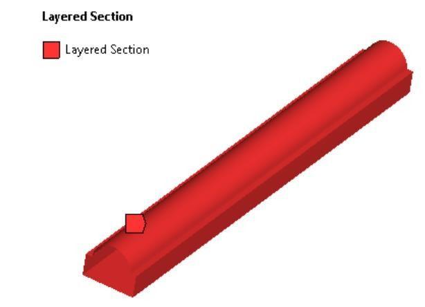
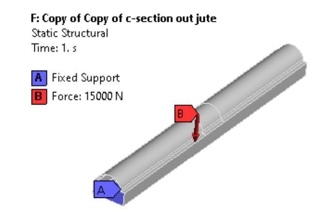

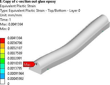
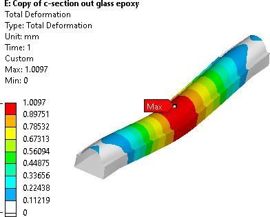
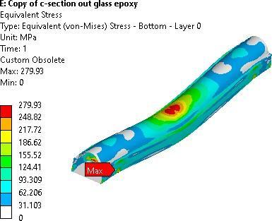
So,inthisanalysiswefindoutthattheglassfibercomposite materialisbetterthanthenaturalcompositematerial
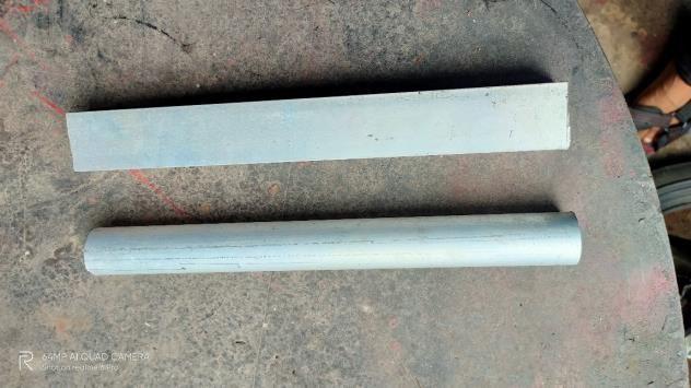


EXPERIMENTAL VALIDATION:
AUniversalTestingMachine(UTM)isusedtotestboththe tensile and compressive strength of materials. Universal Testing Machines are named as such because they can perform many different varieties of tests on an equally diverserangeofmaterials,components,andstructures.
Universal Testing Machines can accommodate many kinds ofmaterials,rangingfromhardsamples,suchasmetalsand concrete, to flexible samples, such as rubber and textiles. ThisdiversitymakestheUniversalTestingMachineequally applicabletovirtuallyanymanufacturingindustry.



The UTM is a versatile and valuable piece of testing equipment that can evaluate materials properties such as tensile strength, elasticity, compression, yield strength, elastic and plastic deformation, bend compression, and strain hardening Different models of Universal Testing Machineshavedifferentloadcapacities,someaslowas5kN andothersashighas2,000kN
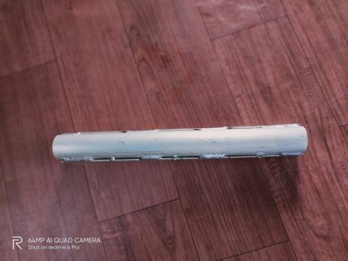
1) Aspergraphshowsthe1mmdeformationgeneratedon the specimen using UTM testing, and load is applied graduallyonthespecimen

2) Whenthedeformation reach nearthe1mm, theloadis betweenthe14KNto16KNaspergraph


3) Asperanalysis thedeformationgeneratedinglassfiber specimen using ANSYS software is 1 mm at the 15000 N load


RESULT AND DISCUSSION
Rectangular B-shape C-shape


TOTAL DEFORMATAION Fig
CONCLUSION
1. We have used aluminum material for electric car bumper beam, existing material used in bumper was steel. The density of aluminumas compared to steel Is less, hence the weight optimization of bumper is done.
2. Afteroptimizationinbumperweight,weneedtocheck the stresses generated in body and concluded that we have to increase the strength of bumper. so, we tried thedifferenttypeof shapes toincreasethe strength of bumper.
3 In this research we considered 3 shapes of bumper namely b-shape, c-shape and d-shape The Static StructuralAnalysis ofallthe3shapesis donebyusing ANSYSsoftware
4. The total deformationand equivalent stress generated in optimized shape i.e., c-shape is 1.2 mm and 280.9 MParespectively
5 After finalizing the shape of bumper, we used composite material ie, jute as natural composite and glassfiberassyntheticfiber Weusedthe2mmlayered forreinforcementofthebumper
6. Total deformation and equivalent stress of optimized bumper(glassfiberreinforced)is100mmand27993 MParespectively.
REFERENCES
[1] Nursherida J M, Barkawi S B, Nuraini A A, “Parametric studyofautomotivecompositebumperbeamssubjected tofrontalimpacts” ,KeyEnggMater,2011.
[2] SimonP,BeggsP,“Anumericalperformancecomparison of a dual-phase steel and aluminium alloy bumper bar system”InternationalJournalofCrashworthiness,2010.
[3] Liu Z, Lu J, Zhu P,“ Lightweight design of automotive composite bumper system using modified particle swarmoptimizer”CompositeStructure,2016
[4] Obradovic J, Boria S, Belingardi G, “Lightweight design and crash analysis of composite frontal impact energy absorbingstructures”CompositeStructures,2012.

[5] Davoodi M M, Sapuan S M, Ahmad D, “Aluminium Concept selection of car bumper beam with developed hybridbio-compositematerial” ,2011.
[6] Mai NJ, Ali A, Sahari B,” Al. Performance of automotive compositebumper beams andhoodsubjected to frontal impacts”,2012
[7] Florida N., Bruno Castanie, Philippe Olivier, “The GAP Methodology: A new way to design composite structures” ,JournalofMaterial&Design,2019.
