FINITE ELEMENT ANALYSIS OF STEEL BEAM-CFST COLUMN JOINTS CONFINED WITH CFRP BELT AND REBAR

Abstract - Concrete-filled steel tube (CFST) is becoming increasingly popular in the construction industry due to their numerousadvantagesoverreinforcedconcretecolumns(RCC).
A CFST column consists of a steel tube filled with concrete.The main strength and stiffness are provided by the steel tube, while the concrete core provides additional compressive strength and fire resistance. CFST columns outperform reinforced concrete columns in terms of strength-to-weight ratio, deformability, fire resistance, improved construction efficiency, lower dimensions, and environmentalperformance. CFST columns are preferred by architects and engineers for structures that require high strength, durability and fire resistance. CFRP is a composite material composed of carbon fibers and a polymer matrix, usually epoxy. CFRP is a material with high strength and stiffness that is extensively utilized in aerospace, automotive and sports applications. This paper focuses on using CFRP as a joint belt as well as rebar in a Square Steel Beam- CFST Column connection system to improve the load carrying capacity by studying various arrangement of the belt layout and explores different configuration of the beam column system where they can be employed through Finite Element Analysis(FEA)withthehelp of ANSYS software.
Key Words: CFST column, Steel Beam, CFRP, Connection system,FiniteElementAnalysis,ANSYSsoftware
I. INTRODUCTION
Beam-column connections are important components of load-bearing structures in civil engineering. They are responsible for transferring loads from the beams to the columns, which then transfer the loads to the foundation. The design, detailing and construction of beam-column connectionshaveasignificantimpactontheperformanceof astructure.Therefore,adequateattentionmustbegivento theseconnectionsthroughoutthedesignandconstructionof the structure. Beam-column connections in reinforced concrete structures are often designed as moment connections. The purpose of moment connections is to transfer bending moments from the beam to the column. Theyarechoseninsteadofshearconnectionsbecausethey give a stiffer and stronger connection, resulting in higher structural performance. Depending on the extent of connectionstiffness,momentconnectionsarereferredtoas either full-strength or partial-strength. Full-strength
connectionsaredesignedtotransferthemaximummoment capacityofthebeamtothecolumn.Theyareoftenfoundin structuresthatrequirehighstiffnessandstrength,suchas high-risebuildingsandbridges.Infull-strengthconnections, thereinforcingsteelofthebeamisembeddedinthecolumn sothatthebeamandcolumnbehaveasasingleunitunder load.Incontrast,partialstrengthconnectionsaredesigned totransfersomeofthemomentcapacityofthebeamtothe column. They are used in low-rise buildings and parking garagesthatrequiremoderatestiffnessandstrength.Bolts, platesorotherfastenersareusedtoconnectthebeamand columninpartialstrengthconnections.
Beam-columnconnectionsrequireprecisedetailstofunction properly. Proper design of the details ensures that the connectionwillwithstandtheloadsandmomentsexpected during the life of the structure. Reinforcing steel must be carefully placed and secured to resist the tensile and compressiveforcestransmittedthroughtheconnection.The geometry of the connection is another important consideration in the design of beam-column connections. Thetransferofforcesandmomentsbetweenthebeamand thecolumnisdeterminedbythegeometryoftheconnection. Dependingontheindividualrequirementsofthestructure, many different connection geometries are used. Common connectiongeometriesincludeboltedendplateconnectors, welded connections, and articulating connections. Beamcolumnconnectionsmustbedesignedandplannedindetail, but construction quality monitoring is also important to ensure their performance. The construction process must ensure thattheconnection isbuilt in accordance withthe designanddetailcriteria.Reinforcingsteelmustbeinstalled in accordance with the design, and appropriate concrete cover must be providedto preventsteel corrosion.Beamcolumn connections are key components of structures in civilengineering.Theirdesign,detailsandconstructionmust be carefully considered to ensure the safety, performance and durability of the structure. The connection type, geometry and details must be selected based on the individual requirements of the structure. Beam-column connections can ensure reliable and safe structural performancewhenproperlydesigned,detailedandquality controlled.Inthispaper,squareconcrete-filledsteeltubes (CFST) with CFRP reinforcement and CFRP belt in beamcolumn connection, strengthening methods and configurationsarestudied.
Modellingandanalysisareperformedinthefiniteelement software(FE)ANSYS2021R2.
II. OBJECTIVE AND SCOPE

A. Objective
Theobjectiveofthisprojectaimstodeterminetheappropriate arrangement for connecting beams and CFST columns using CFRP joint belt and rebar. It also aims to Compare the performanceofsteelandCFRPreinforcingbarsinabeam-CFST column system The final objective is to Analyze the performanceoftheCFSTcolumnconceptinbuildinginterior andexteriorlocation
B. Scope
ThestudyislimitedtoSquareCFSTcolumnswithconnections employingthebeltandreinforcingbarsmadeupofCFRP.The analysis is carried out usingANSYS software, along withthe determinationofbeltlayout.
III. REVIEW OF LITERATURE
JunlongYang etal.publisheda paper on Behaviourof eccentrically loaded circular CFRP-steel composite tubed steel-reinforced high-strength concrete columns. In this paper,Thefailuremodesandloadversusmid-spanlateral displacement curves for specimens with various test parameterswerethoroughlyexamined.Thefindingsofthe experiments reveal that the varying continuities of the exterior steel tube have a significant impact on failure patterns.Crushingofconcreteandbulgingofthesteeltube in the compression side arose near the 1/4 height of the specimenswithgrooves25mmawayfromtheendplateson the external tube, whereas local buckling was observed aroundthemid-heightofthecolumnswithnogapsonthe steeltube.
BenMouetal.publishedapaperonSeismicbehaviourof anovelbeamtoreinforcedconcrete-filledsteeltubecolumn joint This study deals with Four beam-to-RCFST-column specimens were tested under cyclic loading, each with a different cross-section of middle steel tube and transfer sleeves (with or without) to clarify the main seismic indicators,suchasfailuremodes,hystereticperformances, stiffness, degradation, strength degradation, energy dissipationcapacity,andstrainresponsesofthenovelbeamRCFST-columnjoint.Becauseofthesliparoundthetransfer sleeve,thehystereticcurvesofthetestedbeam-to-RCFSTcolumn joint display apparent pinch phenomena. The transfersleeveisthemostimportantcomponentinfluencing thestrengthofthetestedbeam-to-RCFST-columnjunction. Mechanical parameters and failure modes are reliably predictedbytheFEA.
QingJun Chen et al. (2015) presented a paper on Axial Compressive Behaviour of Through-Beam Connections
between Concrete-Filled Steel Tubular Columns and ReinforcedConcreteBeams.InthisstudyAreinforcingring beam is used to increase the connection zone in order to account for any decrease in axial load-carrying capability causedbythediscontinuityinthesteeltubethatencasesthe column.Theresultsoftwosetsofaxialcompressivetesting on 32 beam-column specimens are given. The height and arearatioofthereinforcementintheringbeamarefoundto have a considerable influence on the axial load-carrying capacityoftheconnectingzone.Aformulaforpredictingthe final axial compressive strength of this connection is provided, takinginto accounttheconfinementinduced by numerous layers of ring bars and the influence of local compression.
Junlong Yang et al. (2014) presented a paper on CompressiveBehaviourofCircularTubedSteel-Reinforced High-StrengthConcreteShortColumns.Inthisstudytotalof 12(CTSRC)shortcolumnsmadewithhigh-strengthconcrete aretestedunderaxialcompressivestress.Thekeyvariables of the test are the diameter-to-thickness ratio and yield strengthofthesteeltube,concretestrength,andprofilesteel steel ratio. The failure modes, axial load-displacement curves, and ultimate axial load of CTSRC columns are all thoroughly examined. According to the test results, all specimensexhibitedshearfailureunderconcentricloading. Becauseoftheexistenceofinternalprofilesteel,theshear cracksaroundtheconcreteperimeterwerenotconnected throughouttheentirelength.TheCTSRCcolumns'ultimate concretestrengthandductilityweregreatlyimprovedasa resultofthedoubleconfinementgivenbythesteeltubeand profilesteel,resultinginasignificantimprovementinaxial capacity.
R.S.Aboutahaetal.(2014)presentedapaperonSeismic ResistanceOf Steel-TubedHigh-StrengthReinforced-ConcreteColumns. In this paper Six full-scale columns were tested experimentallyunderconstantaxialloadsandcycliclateral load/displacement.Thefindingsofthetestswerecompared to those of regular high-strength reinforced-concrete columns. According to the findings of this study, STHSRC columns have more lateral strength and ductility than regular reinforced-concrete columns. The ductility of STHSRC columns is not affected by the presence of axial compressive loads when compared to regular reinforcedconcretecolumns.
FaqiLiuetal.(2014)publishedapaperonExperimental and Numerical Studies of Reinforced Concrete Columns ConfinedbyCircularSteelTubesExposedtoFire.Thisstudy proposedFourfull-scaleSTCRCcolumnsandoneconcretefilledsteeltubular(CFST)columnwereaxiallyloadedbefore being exposed to fire until they failed. The columns' measured furnace temperatures, specimen temperatures, axialdisplacementagainsttimegraphs,andfireresistance are given and discussed. The model was then evaluated
against recent fire tests on STCRC and CFST columns publishedintheliteratureusinganonlinearfinite-element modelwithasequentiallycoupledthermal-stressanalysi

IV. METHODOLOGY
AliteraturereviewisconductedonsquareandroundCFST columns.Severalstudieshavebeenconductedtoinvestigate thestructuralbehaviorandotherparametricpropertiesof square and circular CFST. The experimental results of the highestloadcarryingcapacitytestfromthejournalareused tovalidatetheprojectworkandthemaximumloadcarrying value obtained for the joint jacket is 191kN. The result is comparedwiththeresultobtainedinANSYSsoftwareand the resulting percentage deviation is calculated. In this paper, ANSYS finite element software is used to simulate Square Concrete Filled Steel Tube column- Steel beam connectionwithCFRPjointbeltandrebar. Thestudymakes useofdesignmixconcreteanddifferentsteelspecifications in various forms. To improve the structural performance, connectionjacketswithCFRPbeltsareusedtoreinforcethe column.TheTable1belowshowsthegeometricalproperties of the structural components that have been employed in thispaper.
Table -1: Geometrical properties of the structural components
Table -1.1:
Component
Concrete
squarecolumn
Steeltube
BeamIsection
Dimension
Side=265.86mm
Totalheight=2330mm
Thickness=2mm
Beamheight=270mm
Beamwidth=175mm
Webthickness=8mm
Flangethickness=10mm
Totallength=3000mm
Jacket Height=270mm
Thickness=6mm
Beamflange:
Yieldstrength=298MPa
Ultimatestrength=438MPa
Poisson’sratio=0.3
YoungsModulus=200GPa
Beamweb:
Yieldstrength=410MPa
Ultimatestrength=557MPa
Poisson’sratio=0.3
YoungsModulus=200GPa
Steeltube:
Yieldstrength=320MPa
Ultimatestrength=455MPa
Poisson’sratio=0.3
YoungsModulus=200GPa
Jacket:
Yieldstrength=351MPa
Ultimatestrength=505MPa
Poisson’sratio=0.3
YoungsModulus=200GPa
Steelrebar:
Yieldstrength=543MPa
Ultimatestrength=676MPa
Poisson’sratio=.3
YoungsModulus=200GPa
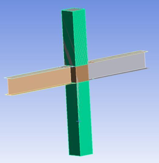
Thetotallengthsofthecolumnandbeamare2330mmand 3000mm,respectively.ConcreteismodelledusingSOLID65 elements,whereassteeltubes,jackets,CFRPbelts,andbeam configurationsaremodelledusingSHELL186elements.The elementtypeLINEBODY188isusedtorepresentrebars.Fig1 showsthemodellingthestructuralsystem
Rebar
Concrete
Diameter=18mm
No:=12
Density=2300kg/m3
Youngsmodulus=33MPa
Poisson’sratio=0.18
Yieldstrength=40MPa
YoungsModulus=240GPa
Poisson’sratio=0.2
CFRP
Ultimatestrength=3800MPa
Density=1.7g/cm3
The square CFST column-Steel Beamconnection systemis modelledusinghexahedralmesh,whichisa4-nodedmesh. Meshingisdoneusingaprogrammemodulatedcoarsemesh withameshsizeof60mm.Loadisappliedasaforceof1187 kN,Fig2[1]showstheboundaryconditionsgiventoexecute theanalysis.
Table -2.2:
Based on Number of Layers
CFRPT2 CFRPbeltcontaining1layer


CFRPT2L2 CFRPbeltcontaining2layers
CFRPT2L3 CFRPbeltcontaining3layers
CFRPT2L4 CFRPbeltcontaining4layers
Table -2.3:
Based on Belt Division
CFRPT2L2 CFRPbeltwithnodivision
CFRPT2L2D2 CFRPbeltdividedinto2belts
Fig 2: BoundaryConditions
The first analysis is based on a Concrete Filled Steel Tube SquareColumn-SteelBeamconnectionwithmultipleCFRP beltlayoutsattheconnectionandCFRPrebartodetermine the best configuration for increasing the load carrying capacityoftheaforesaidsystem.ANSYSsoftwareisusedto constructnineCFRPbeltlayouts,includingfullCFRPrebar withthreedistincttypesofclassificationprofilesfortheCFRP beltprovidedattheconnection.Theclassificationsarebased onthickness,numberoflayersandnumberofdivisionsofthe belt.Table2showsthenameofthespecimensbasedonthe classification.

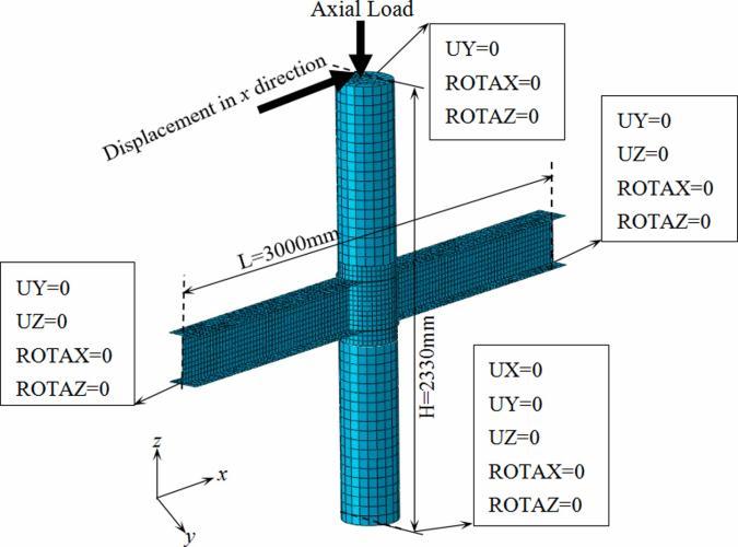
Table -2: Specimen names
Table -2.1:
Based on Thickness
CFRPT1 CFRPbeltwiththicknessof1mm
CFRPT2 CFRPbeltwiththicknessof2mm
CFRPT3 CFRPbeltwiththicknessof3mm
CFRPT4 CFRPbeltwiththicknessof4mm
CFRPT2L2D3 CFRPbeltdividedinto3belts
SquareCFSTcolumn-Steelbeamconnectionismodelledin ANSYSsoftwarewithdifferentbeltlayoutusingCFRPatthe connectionjoint.Fig 3,4,5showsthebelt,beltdividedinto twoandbeltdividedintothree.
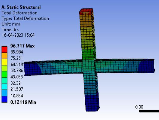
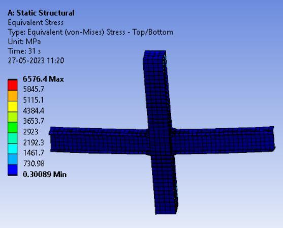
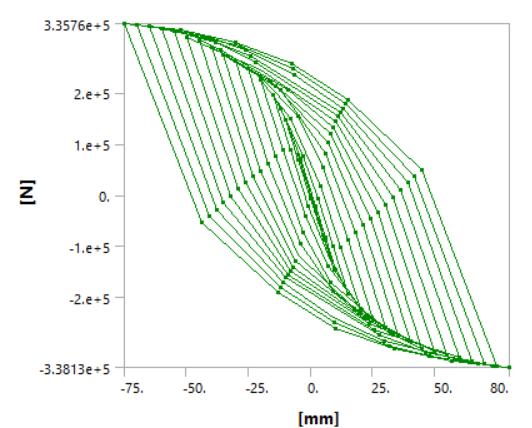
TheperformanceoftheCFSTColumn-steelbeamconnection is analyzed using several configurations of CFRP belt with CFRP rebar. ANSYS software is used for nonlinear static structureanalysis.Theloadcarryingcapacityisinvestigated. Stressdiagramisobtainedafteranalysis.Fig6,7showsthe load-displacementgraphandequivalentstressofCFRPT2.
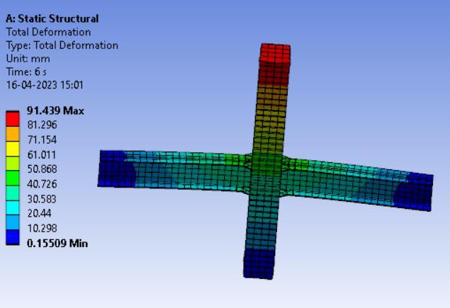
The performance of the novel adopted connection mechanismintheCFSTsquarecolumn-steelbeamjointusing CFRProdsasrebaraswellassteelrodsasrebarisstudied. ANSYS software is used for nonlinear statics structure analysis.Bothsystems'deformation,loadcarryingcapacity, equivalent stress, and strain energy are investigated. Fig 8,9,10,11depictstheobtaineddiagrams.


Furthermore,analysisisconductedontheperformanceofthe suitable belt layout system being CFRPT2L2 with CFRP as rebar and steel as rebar. The modelling, analysis, and comparison of two structural configurations, the first of whichusesCFRPasrebarandthesecondofwhichemploys steelasrebar.

ModellingofCFSTcolumnswith(a)threebeamsattachedto a single column with put forth joint connection (b) four beams attached to a single column with proposed joint connectisperformed.Fig12,13showsthemodelof3beamcolumnsystemand4beam-columnsystem.
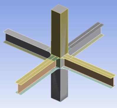

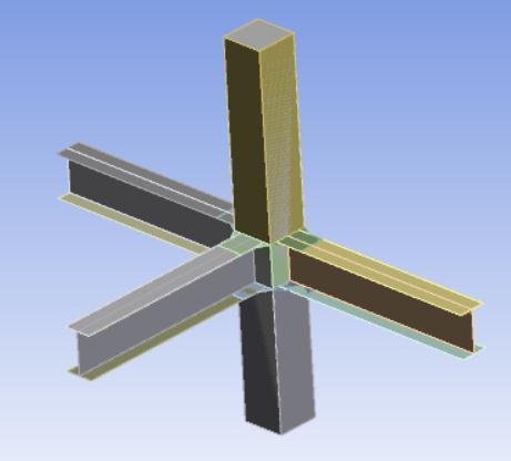
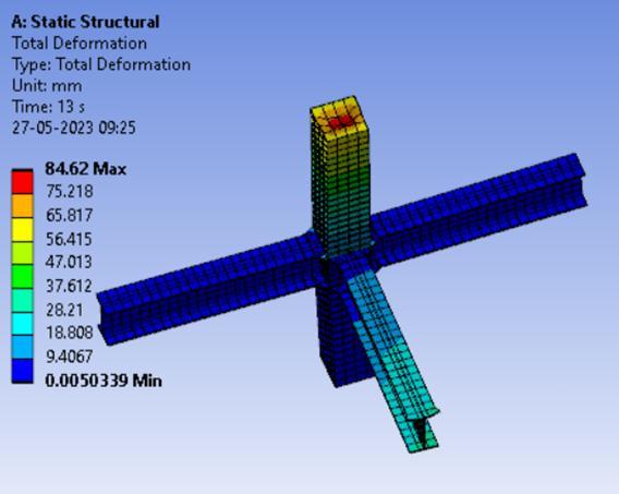
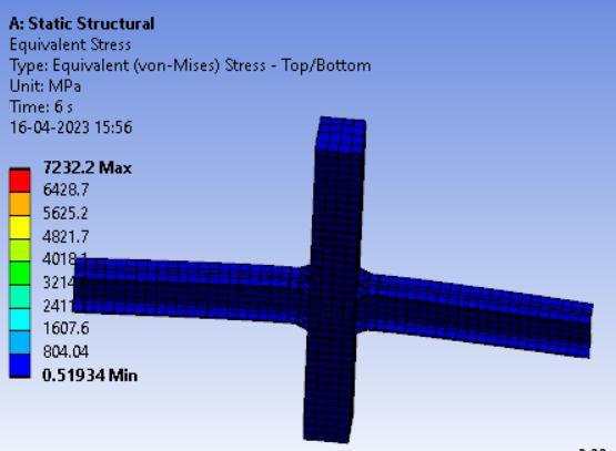
TheperformanceofConcreteFilledSteelTubes-SteelBeam Connection is studied under different layouts of the same with the unique connection presented. A corner column systemwiththreebeamsconnectedtoasinglecolumnandan insidecolumnwithfourbeamsconnectedtoasinglestanding verticalloadbearingstructuralelementaredevelopedand examined. ANSYS software is used to do nonlinear static structuralanalysis.Deformationandloadbearingcapability are investigated. Fig14,15 shows column specimen deformationgraphsandequivalentstressdiagrams

V. RESULT AND DISCUSSION

Theresultofnonlinearstaticstructuralanalysisofdifferent configurationsofCFRPbeltwithCFRPreinforcementbars used in the square CFST column- steel beam led to a combination of the belt elements that provides maximum load-carryingcapacity.Loaddeformationcurveistakenfor eachmodel andthesystemprovided maximumvaluewas selected.TheTable3showstheloadanddeflectionofthe structuralsystemforthedifferentclassificationofthebelt layout.


Fromthisanalysisitwasfoundthatmaximumloadcarrying capacityinthecaseofthicknesswasachievedforCFRPT2 withavalueof338.10kN,CFRPT3showedadecreaseinthe loadingcapacitytoa0.28%percentage.
Considering the next configuration being the number of layers,themaximumloadcarryingcapacitywasachievedfor CFRP T2L4 having a value of 338.890 kNThe peak load differencewashigherwhentheconfigurationchangedfrom CFRPT2toCFRPT2L2being0.47.Thereisagradualincrease intheloadingcarryingcapacitythroughouttheincreasingof number of layers In the case of belt division, the value obtained for load carrying capacity for CFRP T2L2D3 is 338.26 kN and that of CFRP T2L2 is 338.60 kN . the peak
load difference for the case of no division of the belt to divisionbytwothevalueobtainedis5.13.Theloadcarrying capacity decreased for the mentioned to a percentage of 1.53%. The overall increase in the strength of the in comparisontothereferencejournalsystemwas77.21%.

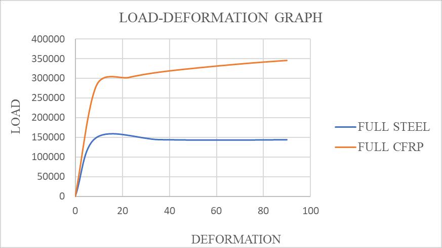
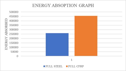
Inthecaseofanalysisofthesuitablebeltlayoutsystemwith CFRPasrebaraswellassteelasrebar,theloaddeflection curves obtainedin bothcases are compared. The chart1,2 below shows the load -deformation graph and energy absorptionoftheproposedtwosystem.
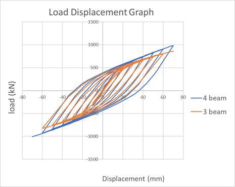
ThecomparisonofloadanddeflectionofCFSTcolumnswith interior and exterior beam system employing novel CFRP jointbeltandCFRPrebar areingivenTable4.Chart3,4,5 showstheloaddeflection,loadcarryingcapacityandenergy absorption comparisons of the two systems we have adopted.
Theload-deformationdiagramshowsthattheCFRPshows more stiffness when compared to steel rebar as plasticity startsafterthedeformationvaluereaches8mminthecase ofsteelwhileforCFRPtillstartsafter11mm.Themaximum displacement allowed during the analysis is 90 mm. Steel shows a deformation of 91.69 mm while CFRP shows deformation of 96.71 mm. After studying the loaddeformation graph the failure for steel starts when the deformationvaluesexceed22mm,whileinthecaseofCFRP, itisafter35mmthatthefailurestarts.Inthecaseofenergy absorption, CFRP shows higher value when compared to Steelwith74.57%increase
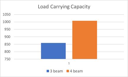
LoadCarryingcapacityincreasesasthenumberofsupport reaction increases with a maximum value of 1008 kN achieved for 4 beam-column connection. The energy absorptionvalueincreasesasthenumberofbeamsjoining thecolumn increases.Deformationand Stresses increases with the number of beams attached to the column with maximumvaluefor4beamsbeing124.19mmand11295 MParespectively.ThecalculatedEnergyabsorptiongraph showedthatthe4beam-columnsystemshowedaincreased absorption rate of 42.26% when in comparison to the 3 beam
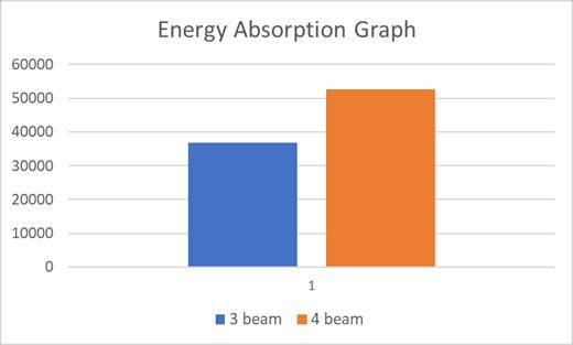
columnjointsystem.
VI. CONCLUSION
SquareCFSTcolumn-steelbeamjointconnectioncontaining CFRPbeltandrebarpatternsaremodelledandanalyzed
•ItwasfoundthattheuseofCFRPasbeltinthejacketandas rebar showed a significant increase in the load carrying capacityofbeam-columnsystemby77.27%
•Optimumthicknesswasfoundtobe2mmandtheoptimum number of layers was found to be 2 with a peak load differenceof1.01
•FullCFRPbeltofthickness2andlayernumber4showed higherloadcarryingcapacitywithavalueof338.890kNbut consideringpeakloaddifferencebeinggreaterwhenlayer numberwasincreasedto2withavalueof0.47,CFRPT2L2 wasadopted.
•Nomenclature of the suitable economical belt layout is CFRPT2L2D3withaloadcarryingcapacityof338.26kNbut CFRPT2L2wasapprovedforfurtheranalysisforhavingthe maximum load carrying capacity of 338.600 kN in comparison
•CFRP rebar has a higher modulus of elasticity than steel rebarwhichmeansitcanresistdeformationunderstressto a greater extent than steel this property can lead to an
increaseinitsloadcarrying capacityascomparedtosteel rebar which showed only a load carrying capacity of 147.70kN. Energy absorption also increased by 74.57% whenCFRPwasusedasarebar.
•Energyabsorptionriseswhensupportresponsesincrease, and this may be attributed to an extra load route for distributinganddissipatingenergyduringseismicorother loading circumstances in the case of a four beam-column system with 42.26% increase in comparison to 3 beamcolumnsystem.Itshouldalsobenotedthattheadditional beam in this system adds redundancy to the system. As a result,theoverallresilienceandcapacityoftheconnection enhances with an increase of 23.138% in case of 4 beamcolumnsystem.
•Itisobservedthatwithasuitableconfigurationofthesteel beam-CFSTsquarecolumnjointconnectionconfinedwith CFRP belt and CFRP rebar, square column can achieve a higherloadcarryingcapacityincomparisonwithacircular columnofthesamevolumeasweobtained338.600kN
VII.FUTURE SCOPE
Newinnovativematerialscanbediscoveredandstudiescan beconductedontheirengineeringpropertiessoastocarry outresearchesonimprovingthestrengthanddurabilityofa structuralelementemployingthesenewmaterials.

Materialsthatcanbeeconomicallyadoptedinconditionsof uncontrolled and unpredicted force application can be studied. Different configurations and layout of the beamcolumn system can be explored and researched upon for square columns and ways to improve their strength in comparisontocircularcolumns.
REFERENCES
[1] Xuhong Zhoua,b, Jiepeng Liua,b, Guozhong Chenga,b,⁎, Dan Gana,b, Y.Frank Chena,b , New connection system for circular tubed reinforced concrete columns and steel beams, Ministry of Education, Chongqing 400045, China b School of CivilEngineering,ChongqingUniversity,Chongqing 400045,China
[2] Eurocode4,DesignofCompositeSteelAndConcrete Structures, Part 1.1, General Rules and Rules for Building, British Standards Institution, London, 2004(BSEN1994-1-1:2004).
[3] Ge Hanbin, Usami Tsutomu. Strength of concretefilledthin-walledsteelboxcolumns:experiment.J StructEng1992;118(11):3036–54.
[4] Wang XD, Liu JP, Zhang SM. Behavior of short circular tubed-reinforced-concrete columns
subjected to eccentric compression. Eng Struct 2015;105:77–86.
[5] LiuJP,ZhangSM,ZhangXD,GuoLH.Behaviorand strength of circular tube confined reinforcedconcrete(circularTRC)columns.JConstrSteelRes 2009;65(7):1447
58.
[6] WangWD,GuoZF,ShiYL.Finiteelementanalysison behavior of the joint with steel tube confined concrete (STCC) column to reinforced concrete beam.AdvancedMaterialsResearch2011;243:527–30.

[7] ZhouXH,ChengGZ,LiuJP,GanD,ChenYF.Behavior of circular tubed-RC column to RC beam connectionsunderaxialcompression.JConstrSteel Res2017;130:96–108.
[8] Zhou XH, Li BY, Gan D, Chen YF. Connections between RC beam and square tubedRC column under axial compression: Experiments. Steel and CompositeStructures2017;23(4):453–64.
[9] Zhou XH, Zhou Z, Gan D. Cyclic testing of square tubed-reinforced-concrete column to RC beam joints.EngStruct2018;176:439–54.
[10] Nakahara H, Yin H. Experimental study of structural frame composed of steel jacketing concrete-columnandsteel-beamwithself-centering capacity. 11th International Conference on Advances in Steel and Concrete Composite Structures,Beijing,China.2015.
[11] Zhou XH, Cheng GZ, Liu JP, Yang YL, Chen YF. Shear transfer behavior at the circular tubed column-steel beam interface. Thin-Walled Structures2019;137:40–52.
[12] Cheng GZ, Zhou XH, Liu JP, Chen YF. Seismic behaviorofcirculartubedsteelreinforcedconcrete column to steel beam connections. Thin-Walled Structures
