DC-DC Converter With Multiple Inputs For Hybrid Electric Vehicles Application.
 P. Sai Pershad*, Dr. M. Sushama**
*(M. Tech, Department of Electrical Engineering, JNTUH University College of Engineering, Hyderabad, India, **(Professor, Department of Electrical Engineering, JNTUH University College of Engineering, Hyderabad, India, ***

Abstract - A proposed DC to DC converter with multiple inputs for electric and hybrid vehicles (HEVs). The goal of the study is to increase production efficiency in comparison to earlier research. the converter's three sources of electricity are the battery, photovoltaic or PV panel, and the fuel cell. The roof-mounted PV panel fills the battery improves performance and reduces the consumption of fuel, while the FC serves as the primary power source. Regardless of whether certain resources are unavailable, the converter continues to power the load as required. The study also discusses and implements a power management technique in the control mechanism.
Key Words: Multi input Converter, HEVs, Fuel cell, Photovoltaiccell
1. INTRODUCTION
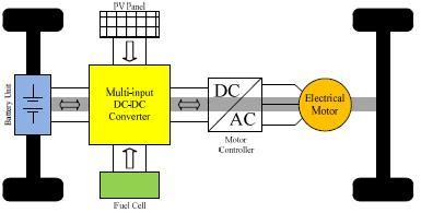
Theprimarydisadvantagesofcarsfueledbypetroleumor diesel are an increase in global temperature and the unavailability of petroleum derivatives. To overcome the above-describedchallengesandtodemonstratethecapacity ofrenewableenergiestogenerateelectricity,Parallelelectric automobiles and modular electric cars have seen the appearance of automotive designers. Figure 1 depicts the overall framework of an electric hybrid car fueled by renewable energy. Their biggest drawbacks are limited driving range and lengthy battery recharge times. They might,however,haveV2Gcapabilitybyutilizinganinboth directionsonandoffcircuitcharger.Theprimaryoutputsof powercellsarepurewaterandwarming.Nonetheless,the primary concerns with FCs are astronomical costs and inadequate transitory implementation. It should be noted that cars primarily fueled using FCs can hybridized using ESSs as well. Minimal volumes of research on an electric vehicleandhybridelectricvehiclescircuitryarerepresented intheliterature.Ithasanelevatedoutputsinceitachieves turn-on switching to no voltage with all being identical. However,itfallsshortofanintwodirectionsinterface.Asa result, it can't be used in applications that require ESS. Furthermore, the converter's large voltage rise makes it appropriate for small data voltage tasks. Regardless, the substantialnumberoftransistorsandactivepartsreduces efficiency. The flow of electricity among the natural resources,theenergystorageunit,andtheengine'smotor mustbecontrolledbythe controlapproachestablishedin thevehicle'sprocessor.Themajortasksofthecontrolplot
are to make the best use of power supplies, provide continuousinterestpower,andkeepthepowersourceand solar panels in their optimal location. In any scenario, the needed HEV converter ought to eliminate energy from Photovoltaic&FC.Amultipurposeinputconvertingdevice mayprovidevoltagetoademandfromnumeroussourcesof energysimultaneouslyorindependently.
As the fundamental price of photovoltaic panels is considerable, MPPT computation has to be utilized to generateseparatedelectricityfromthephotovoltaic
A unique DC to DC is presented for the photovoltaic electricity an electrical part, and a storage device to the network.Furthermore,DCoutputisenhancedovertypical conversiondevices.Atthispoint,MPPTforphotovoltaiccells may be obtained. The energy source may be loaded and dischargedforpoweringtheboard.Thesuggesteddesignis addressedinthenexttwoparts,asarevariousoperational types.
2. SUGGESTED TOPOLOGY FOR CONVERTERS
Figure 2 depicts the construction of the intended 3-input directcurrenttodirectcurrentstep-upchopper.Itismade upof2normalboostconverters,withoneofwhichhasan additional capacitor. The converter's trait makes it appropriate for mixed systems. In the energy control and administration section of this study, the behavior of the chopper with regard to overseeing its energy sources is analyzed.TheenergyoutputofVpvandVfcisdependingon their own characteristics, making them two distinct electricalsources.BothL1aswellasL2arethedatainput
masks for solar panels and fuel cells, respectively. Photovoltaicandfuelcellunitscanbeconvertedtocurrent suppliesbyconnectingL1andL2incombinationwiththe inputsources.TheequivalentresistancesofVpv&Vfcarer1 &r2,accordingly.Thecorrespondingresistanceofdemand attached to the direct current bus is known as Rload. The power IGBTswitches are S1, S2, S3, and S4. The types of operationthatareestablishedusingdiodeD1,D2,D3,and D4arediscussed.OutputcapacitivedeviceCoandcapacitive element C1 is utilized for boost the resultant value. Continuous conduct modeis being used by the system to provide steady current via the lowest possible level of currentfluctuation.
switchedONduringthistimeperiod,alongwiththediode D3.
Mode 2 ( T<t< T):[Figure.3(b)]


D2iskeptON,SwitchS1isswitchedOFFandswitchesD3 and S2, S3 are all remaining ON. Inductor L1 is being depletedwhileinductorL2isstillbeingsupplied
Mode 3 ( T<t<T)[Figure.3(c)]:
S2 is switched OFF, D3 and S3 were remainedON, S1 is switchedONduringthistimeperiod.InductorL2isdrained viaVpv+Vc1-VoandinductorL1ischargedwithVpv
ThevoltageoncapacitorC1andtheoutputvoltagecanbe measuredbyconductingthevolt-

Additionally,wehavethevoltageofcapacitorC1byapplying theamp-secondbalancingbothcapacitorsC1&Co.
3. OPERATION MODES:
The fundamental ideas behind the suggested designare coveredinthissection.Theconverteroperatesin3states:1. Thereisnobatteryused;PVandFCsupplytheload.2.The photovoltaicenergy,FuelCell,andbatteryallcontributeto supplyingtheload.3-Thestoragedeviceisintheelectrical chargingstageandthephotovoltaicpanelandfuelcellare supplyingthedemand.
3.1 First operation state (While the storage device is not being used, Photovoltaic and fuel cell supply the demand.)
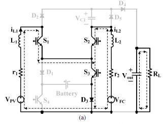
Thereexist3operatingmodesinthiscondition,asshownin Figure 3. The system is working in this condition without anybatterychargingordischarging.Asaresult,currentcan moveviaD3andS3orS4andD1inoneoftwoways.D3and S3areregardedasacommonrouteinthiswork.S4andD1 maybeselectedasanoption,though.SwitchS3isONwhile switchS4isalwaysOFFunderthiscondition.
Mode 1 (0<t< T):[inFigure.3(a)]
Thesourcesof electricityVpvandVfc,respectivelycharge inductors L1 as well as L2 Switches S1, S2, and S3 are
Battery isn't utilized in this scenario, thus we have the followingvalues

3.2 Second operation state (While the storage device, Photovoltaic and fuel cell supply the demand.):

Ithas4operatingmodesinthisstate,asshowninFigure4. The amount of power is provided by multiple input devicesinthisstage.Thereisjustonecurrentpathwayinthe firstmode.However,therearetwoexistingrouteseitherD3 andS3orD1withS4intheremainingcategories.Current movesviaS4andD1inthisscenario.Inthisscenario,Switch S4isalwaysON.
Mode 1 (0<t< T):
S1,S2,S3,andS4havebeenswitchedONduringthistime. AccordingtoFigure.4(a),L1ispoweredbyVpv+Vbattand L2ispoweredVfc+Vbatt
Mode 2 ( T<t< T):
D1andS1,S2,S4havebeenswitchedONduringthistime. ChargeisappliedtoL1andL2byVpvandVfcaccordingly [Figure.4(b)].

Mode 3 ( T<t< T):
D1,D2,S2,andS4areswitchedONduringthistime.L2gets poweredbyVfcwhileinductorL1isdrainedtocapacitorC1 [inFigure.4(c)].

Mode 4 ( T<t< T):D1,D4,S1andS4havebeenswitched ON during this time. Inductor L2 empties C1 to Cowhile inductorL1isenergizedbyVpv.[inFigure4(d)]. Bydoingvolt-secondbalancelowoverthefilters


By puttingamp-secondbalancetocapacitorsCoandC1, weget:
3.3 Third operation state (While the storage device is being energized,Photovoltaic and fuelcellsupply the demand.)
Therearefourpossibilitiesinthisstage,as showninFigure5.PVandFCchargethestoragedevicewhile providingtheload.Ithastwoalternatives.eitherD3andS3 orS4andD1inthefirstandsecondoperationalmodes.In thissituation,thecurrentwillflowalongthelineconnecting S4 and D1. Switch S3 is always OFF in this condition, and diodeD1isconducting.

Mode 1 (0<t< T):
D1andS1,S2,S4,havebeenswitchedONduringthistime. ChargeisappliedtoL1andL2byVpvandVfcaccordingly[in Figure.5(a)].
Mode 2 ( T<t< T):
D1,D2,S2,andS4areswitchedONduringthistime.L2gets poweredbyVfcwhileinductorL1isdrainedtocapacitorC1 [inFigure.5(b)].


Mode 3 ( T<t< T):
S1, S2, D1 and D3 have been turned ON during this time. LoadedbyVpv-Vbatt&Vfc-Vbatt,respectively,areinductors L1andL2.[inFigure.5(c)].


Mode 4 (d3T<t<d4T):
S1,S4,D1,andD4havebeenswitchedONduringthistime. L2getsdrainedbyVfc-Vc1-VowhileinductorL1ispowered upbyVpv-Vbatt.[inFigure.5(d)].
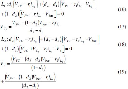
Bydoingvolt-secondbalancelowoverthefilters:
Byputtingamp-secndbalancetocapacitorsCoandC1,we get:
thepowerbystoragedeviceandcurrentmaybeacquired as:
Thepatternsforallconditionsandallmodesareshownin the figure 4.1. A saw-tooth waveform is contrasted with impulses d1, d2, d3, and d4 which can each individually controlled the state of the electricity to complete the switching process. 1 to 4 diode signals can be utilized for adjusting energy every source's the photovoltaic FC, and storageareproducingwithnotconsideringthevoltageofthe outputintoaccount.


4. EXTRA BENEFITS OF THE DEVICE THAT MAKE IT RELIABLE:
Therecommendedconversiondeviceofferstheadvantageof justusingasinglesourceifeitherofthesourcesofelectricity are unable to provide energy. The suggested converter's reliabilityandsecurityareimprovedbythisfeature.These variouspotentialstateshavebeenoutlined:

•OnlyPVisactive:
Because fuel cells take a while to start up, this condition typically occurs when an automobile starts nor when the fuel system is empty. In this condition, PV can chargeor depletethebattery.SwitchS2isswitchedoff to allowthePVtorunindependently,andpowerfromthePVis then transmitted to the output capacitor Co rather than capacitorC1.Inaccordancewiththearchitectureshown,a storage device can be supplied and depleted using solar powerandswitchesS1,S3,andS4.
•OnlyFCisactive:
FCistheprimaryinputforprovidingthedemandby HEVsseparatelysinceVpvissmallerthanthatofVfcandis dependent on the climate. As a result, an additional diode (D5) pair with capacitor C1. Once capacitor gets filled up, diode D5 is turned off. When the FC is used alone, the capacitorC1drainstillthevoltageacrossitreacheszero.As thevalueofthevoltageoverC1becomesnegative,diodeD5 turnsonandthusclipsthevoltageoverC1.
5. SIMULATION RESULTS:
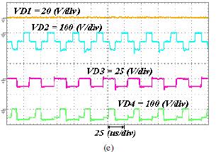
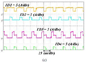
ThefirstinductiveelementL1hasanintrinsicvalueof550x 10-6 (H),whilethesecondinductivecomponenthasavalue of650x10-6H.Thecapacitanceofthecapacitorsusedinthe conversion device are 470 x 10-6 F. Figure 5depicts the outcomesoftheinitialstateoperation.Figure5(a)depicts thevoltageofoutputandcapacitorC1.Taking20Vforevery inputvoltagemeasurementcorrectlyraisedtoaround110V. Figure5(b)depictstheinductorscurrent,whereasFigures 5(c)depictthediodecurrentsand5(d)depictspowerswitch currents. Figures 5(e) illustrate the of diode voltage and Figure 5(f) depicts power switch voltages. The inductive electricalcurrentsarearound2Ampsintheexperimental findingsofthefirstoperationalmode.AsshowninFigure.
5(c) the diode current D1 and in Figure 5(d) diode D3 is forwardbiased,whileswitchS3isonandswitchS4arezero whichcausesittobeopencircuited.Theremainingelements are swapped at a frequency of 30 kHz. As illustrated in Figures5(c)showsthediodecurrentofD1andFigure5(d) showsswitchcurrentS4arezero,butthecurrentsofswitch S3 and diode D3 are constantly on, resulting in a volts isroughly zero. The remaining parts are swapped at an oscillationratearound30kilohertz.


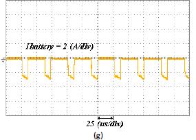
Figure6depictstheoperationoutcomesofthesecondstate. Figure6(a)depictstheoutputandvoltageofcapacitorC1. Figure6(b)showsthecurrentviainductiveelementsFigure 6(c) illustrate the diode currents and 6(d) power switch currents. Figures 6(e) show the diode voltages and 6(f) powerswitchvoltages.Figure6(g)depictsthecurrentofthe batteries.Inthisscenarioofoperation,inductivecurrentsis 1.99Ahavingfluctuatingwith0.9A.Furthermore,theenergy storagedeviceisdepletedtoacurrentof4Aflowingacross device.Throughthestateoffunctioning,eachoftheswitches areturnedandonlydiodeD3remainsinactive.Asaresult, theconverter'sefficiencyinthismodewasinferiortothatof theremaining.
Figure 7 depicts the experimental findings for the third condition.Figure7(a)depictsthecapacitorvoltageC1and the intended voltage of the converting device. Figure 7(b) shows inductor currents. Figures 7(c) illustrate the diode currentsand7(d)illustratethepowerswitches,respectively.


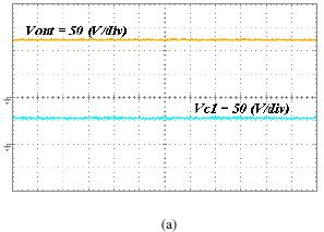
7. ResultsofSimulation3operatingstate
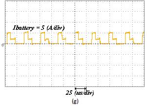

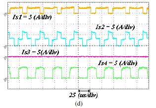
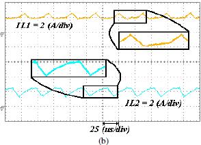
Theoutcomesverifytheconverter'soptimisticeffectiveness in every state of operation. The suggested converter performanceisgreaterthantheremainingonesintheinitial operating state. The suggested converter's lowest performanceisaround85indrainingmode.Becausethere aremoreswitchesinthisstatethaninothers.Asaresult,the lossofswitchinginthisstateisgreaterthaninotherstates. Inthisendeavor,theoutputintendedvoltageisaround120V andthephotovoltaicrequiredcurrentisapproximately2Ain thefirststage.Aspreviouslystated,thevoltageofthebattery is0inthissituation.Inthesubsequentportionofthestudy, the photovoltaic guide current is increased to 4A, the fuel cellsguidecurrentisreducedto2A,andthevoltageneeded for output is 120V. A current surge of inductive device is acceptable. and the secondinductive element's current is somewhatlowerasitwaspreviously.Thebattery'sflowof current is around 6A. Because of the cited standards, the systemoperatesinbattery chargingmodenearto39.9W. The output voltage fluctuates during these three steps, although it is unimportant. The converter's response to transients is satisfactory and may be used in HEV applications.
6. CONCLUSION:
This investigation proposes and deconstructs a revolutionary 3-input DC to DC conversion device. The

conversiondeviceiscapableofprovidingtheneededenergy bydemandwithouttheuseofanassortmentofsupplies.The converter's optimistic performance and used control approachprovidegreatreliabilityforusageincommercial and residential applications. The converter's output is presentedforthreedistinctoperatingmodesthatisutilized.
7. REFERENCES:
[1]A.Ostadi,andM.Kazerani.“OptimalSizingoftheBattery Unit in a Plug-in Electric Vehicle,” Vehicular Technology, IEEE Transactions on, vol.63, no.7, pp.3077-3084, Sept. 2014.
[2]P.Mulhall,S.M.Lukic,S.G.Wirashingha,Y.-J.LeeandA. Emadi"Solar-assistedelectricautorickshawthreewheeler", VehicularTechnology,IEEETransactionson,vol.59,no.5, pp.2298-23072010.
[3]H.J.Chiu,andL.W.Lin.“Abidirectionaldcdcconverter for fuel cell electric vehicle driving system", IEEE Trans. PowerElectron.,vol.21,no.4,pp.950-958,2006.
[4] T. Markel, M. Zolot, K. B. Wipke, and A. A. Pesaran. “Energystoragerequirementsforhybridfuelcellvehicles”, 2003,AdvancedAutomotiveBatteryConf.
[5] S. Miaosen.“Z-source inverter design, analysis, and its applicationinfuelcellvehicles”,Ph.D.dissertation,Michigan StateUniv.,EastLansing,USA,2007.

