Comparison of Performance for Power Quality Improved EV Battery Chargers using Bridgeless Cuk Converter and SEPIC PFC Converter
Namburi Ramya Sri
(M. Tech, Department of Electrical Engineering, JNTUH University College of Engineering, Science and Technology Hyderabad, India) ***

Abstract- This paper compares the performance of two powerfactorcorrection(PFC)converters,thebridgelessCuk converterandtheSEPICPFCconverter,inimprovingpower quality for electric vehicle (EV) battery chargers. The converters are evaluated based on power factor, total harmonicdistortion(THD)andefficiency.Simulationsusing anEVbatterychargingsystemdemonstratetheconverters effectiveness in reducing THD, improving power factor, achieving high efficiency, and maintaining stable output voltage.Thefindingsaidinselectinganddesigningefficient and reliable EV charging systems, contributing to grid stability.Furthermore,thisresearchlaysthegroundworkfor futureadvancementsinpowerelectronicsforEVcharging applications.
Keywords: Electric vehicle battery chargers, power factor correction, bridgeless Cuk converter, SEPIC PFC converter, power quality improvement, total harmonic distortion (THD), efficiency, voltage regulation
1.INTRODUCTION
Traditionalelectricvehicle(EV)batterychargersencounter issues with power quality and efficiency due to the nonlinearbehavioroftheinputdiodebridgerectifierusedinthe AC-DC conversion stage. These chargers draw irregular current from the mains, leading to a deteriorated power factorandhightotalharmonicdistortionofupto55.3%[1]. TocomplywithinternationalstandardsliketheIEC6100-32 [2] and enhance input power quality, power factor correctionconverters(PFC)arereplacingtheconventional chargersatAC-DCconversionstage.
The efficiency of DBR-fed chargers is hampered by conductionlossresultingfromtheinputdiodes.Bridgeless PFC converters offer a viable solution by reducing conductionlossandenhancingpowerqualityinEVchargers. Several improved power quality converters have been examinedin[3].Theutilizationofbuckandboostconverters [4] in EV chargers for power factor correction (PFC) is unsuitable due to their limitations in current shaping and dutycycle.Thebridgelessbuck-boostconverter[5]presents anattractivesolutionforPFCinEVchargersasitallowsa wide range of duty cycle variation to control the output voltage.
CukandSEPICconvertershavebeenanalyzedin[6].TheCuk converter exhibits favorable charging characteristics with low ripple in battery current, unlike the SEPIC converter, which has the limitation of discontinuous output current. ThebridgelessCukconverter[7]providesadvantagessuch aslowerinputcurrent,reducedEMI,andstraightforward implementation. However, it also has drawbacks like a floating neutral, floating terminal for the load, and circulatinglosses.Currentshapingisachievedusingaverage current mode control and voltage follower mode control. The converter's operation mode, either CCM or DCM, determinesthePWMswitchingstrategy.
In order to achieve an affordable charging solution, the converter operates in DCM (Discontinuous Conduction Mode)withPWM(PulseWidthModulation)controlbased onvoltagefeedback.Byimplementingthisapproach,costeffectiveness can be achieved in the charging process. Variable duty cycle control-based PWM switching is employedforitsexcellentcurrentshapingcapability[8].A flybackconverterisalsodesignedtooperateinDCMmode [9],featuringacascadeddual-loopcontrollerforregulating battery charging in CC and CV charging regions. In accordance with SAE standard J1772 [10], EV battery chargersshouldbelightweight,efficient,cost-effective,and providelowripplecharging.
Tofulfiltheserequirements,aresearchworkComparisonof Performance for Power Quality Improved EV Battery Chargers using Bridgeless Cuk Converter and SEPIC PFC Converter is proposed which involves the design and development of a bridgeless Cuk converter, a Flyback converter with a control unit, and SEPIC (Single-Ended PrimaryInductanceConverter)aFlybackconverterwitha controlunit.ThesedesignsareimplementedusingSimulink to ensure optimal power factor correction (PFC) characteristics. A comparative analysis is performed to evaluate the effectiveness of these two solutions for EV battery chargers. The charger offers simplified control, reduced size and cost, improved efficiency, elimination of circulatinglosses,andreducedelectromagneticinterference. ThecontrolofthePFCconverterissimplifiedbyemploying thesamegatedriveandcontrolcircuitryforeachhalfcycle.
Inthispaper,thedesignoftheoutputinductorsfortheCuk converter is optimized specifically for Discontinuous ConductionMode(DCM),resultinginareductioninboththe
costandsizeoftheconverter.Comparedtootherdesigns, the Bridgeless Cuk converter significantly minimizes the numberofcomponentsinvolvedwithinoneswitchingcycle, leadingtoenhancedefficiencyofthecharger.Theoperation oftheintermediatecapacitorsindependentlyinbothhalves oftheconvertereliminatesanycirculatinglosses.
Theimplementationofacommongroundarrangementfor thetwoswitchesintheproposedtopologycontributestoa decrease in electromagnetic interference. The DC link voltageoftheCukconverterisregulatedatacontrolledlevel of 400V. To validate the effectiveness of the proposed EV charger, a simulation model has been developed and demonstrates improved performance in steady-state conditions,whilecharginga48V,100Ahlead-acidbatteryfor electricvehicles(EVs).

2. CONFIGURATION, OPERATING PRINCIPLE, DESIGN OF BRIDGELESS CUK CONVERTER BASED EV BATTERY CHARGER
A. Configuration of Bridgeless Cuk Converter Based EV Battery Charger
Figure 1 illustrates the recommended configuration of an advancedEVcharger,comprisingaflybackconverteranda bridgeless(BL)Cukpowerfactorcorrection(PFC)converter. ThesuggestedPFCCukconverteroperateswithcomponents includingoutputdiodeDo1, switchS1,inputinductorLi1, andoutputinductorLo1forthepositivehalf-cycle.Similarly, duringthesubsequenthalfcycle,switchS2,inputinductor Li2,outputdiodeDo2,andinductorLo2areutilized.ThePFC CukconvertermaintainsaconstantDClinkvoltagethrough the use of a single voltage sensor and single-loop voltage feedbackcontrol.
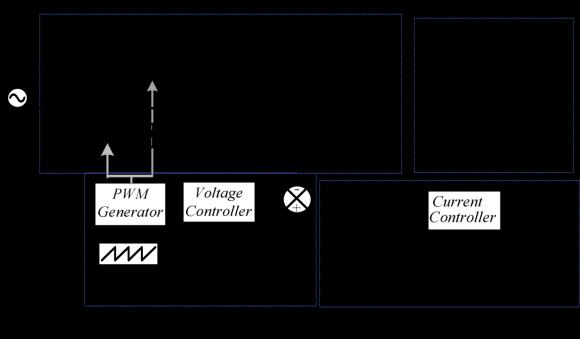
Acascadeddualloopcontrollerisemployedintheflyback convertertoregulatethebatterycurrentduringthecharging processinbothconstantcurrent(CC)andconstantvoltage (CV)regions.
B. Operating Principle of Bridgeless Cuk Converter Based EV Battery Charger
This section outlines the fundamental operation of the proposedEVcharger.Duetowaveformsymmetry,onlythe positive half cycle of the BL converter is considered in Figures2(a)-(c).
1. OperationofBLCukPFCConverter
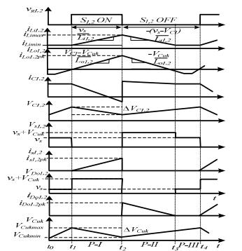
At time t1, the gate pulse applied to switch S1 initiates the first mode of operation (P-I) for the positivehalfcycle,resultinginalinearincreasein thecurrentflowingthrough input inductorLi1as depicted in Figure 3. Capacitor C1 begins dischargingthroughswitchS1andoutputinductor Lo1,asshowninFigure2(a).
Attimet2,whenthegatepulsestotheswitchare turned off, mode P-II begins as the polarity of capacitor C1 reverses. Figure 2(b) illustrates the dischargeofstoredenergyfrominputinductorLi1 throughconvertercapacitorC1anddiodeDo1.The dischargeoftheoutputinductoroccursthroughthe outputdiodeandtheDCconnectioncapacitorCcuk. Mode P-III starts at time t3 when the output inductor Lo1 is fully drained, as shown in Figure 2(c),and thecurrentthroughtheoutputinductor dropstozero.Theflybackconverterconnectedto the output of the PFC Cuk Converter receives the requiredpowerfromtheDC-linkcapacitorCcukas the Cuk Converter operates in DCM mode at this point.
2. OperationofFlybackConverter
Theflybackconverter'soperationisexaminedbased onthediscontinuousconductionmode(DCM)ofthe magnetizing inductance in the high-frequency transformer(HFT).Thecurrentflowingthroughthe magnetizing inductance Lmf increases steadily, storingenergywhentheflybackswitchSfisturned on.Atthismoment,thedotconventionoftheHFT causes the output diode Df to be reverse biased. Duringtheswitch-offphase,whenthepolarityofthe HFTisreversed,theoutputpoweristransferredto thebatteryastheoutputdiodeDfbecomesforward biased.However,duringeachswitchingcycle,when themagnetizinginductanceisfullydischarged,the required battery charging current in constant current (CC) mode is supplied by the output capacitorCbatt.
Fig.3.Associatedswitchingbehaviorofthedifferent componentsoveroneswitchingcycle.
charger to give better PQ characteristics, and an isolated converterisusedtoregulatethechargingcurrentflowing throughtheelectricvehiclebattery.Withahighvoltagegain, the output of this PFC converter is kept constant at 300V. Whencomparedtoacontinuousconductionmode(CCM)based design in the PFC circuit, the DCM design for this converter uses fewer sensors. In turn, this lowers the converter’s price and control complexity. The suggested converterisanalteredversionofastandardSEPICconverter with a few auxiliary component’s version of a standard SEPICconverterwithafewauxiliarycomponentsaddedto raise the voltage gain above that of existing non-isolated SEPICconverters.
C.
Based on the given design expressions in [11], an electric vehicle (EV) charger is created by combining a bridgeless CukconverterandaflybackconverteroperatinginDCM.The symbolsandconstantsusedinthecalculationscorrespond tothevaluesdepictedinFigure1.
3. OPERATING PRINCIPLE AND DESIGN OF SEPIC PFC CONVERTER BASED EV BATTERY CHARGER
A. Operating Principle of SEPIC PFC Converter based EV battery Charger
As seen in Fig.4, the enhanced SEPIC converter-based EV charger A PFC converter is used at the front end of the
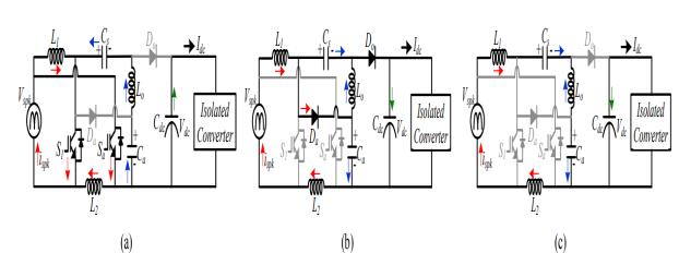
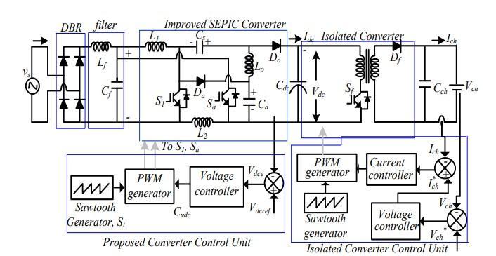
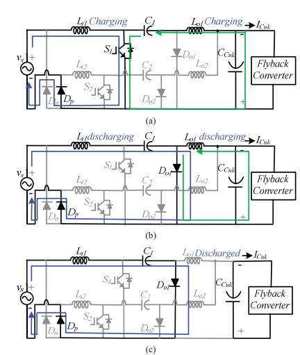
Fig.5.OperatingprincipleoftheenhancedSEPICPFC (PowerFactorCorrection)converter.Itshowcases threemodes:ModeI,ModeII,andModeIII.
1. OperationofSEPIC

Converter
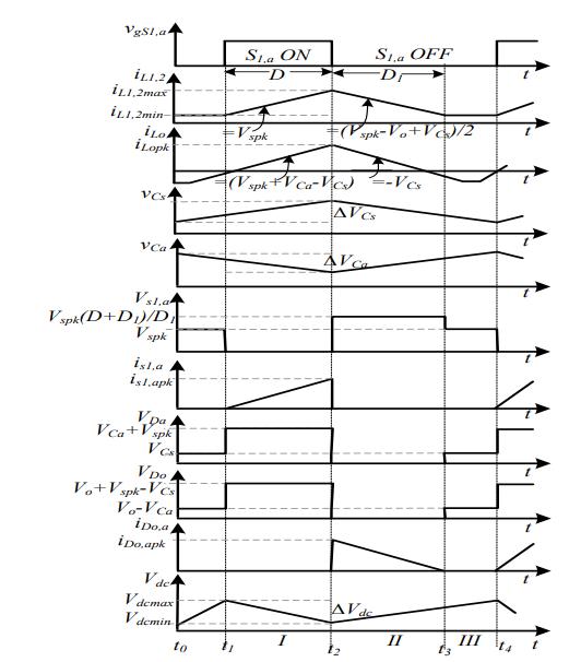
The primary switch S1, input inductor L1, output inductorLo,intermediatecapacitorCs,andoutput diodeDomakeupthisPFCconverter.Theauxiliary switchSa,inputinductorL2,intermediatecapacitor Ca,anddiodeDa makeupthePFCconverter.The operation of the converter is described in the following manner, assuming that the output inductorofthisSEPICconverterissettofunctionin DCMforoneswitchingcycleTs.(t1-t2)Mode-I:In this configuration, the instant t1 results in the
activationoftheauxiliaryswitchSaaswellasthe main switch S1. As seen in Fig. 5 (a), the output diodesDoandDaarereverse-biased.
theyreachzero.ApplyingKVLinthismodetothe loopformedbyVspk,L1,Cs,Lo,Ca,andL2resultsin
(5)
whereVca,asdepictedinFig.6,isthevoltageofthe auxiliarycapacitor.Iftheaveragevoltageacrossthe inputinductorsissettozero,itproduces
(6)
Similartothis,byusingthevolt-secondequationto describetheproposedconverter'sinputandoutput inductorsthroughoutthedutycycleD,thefollowing relationshipsaregenerated:
AccordingtoFig.6,thecurrentsflowingthroughthe two input inductors (iL1, iL2) and the output inductorcurrent(iLo),whicharewrittenasfollows, riselinearlywithaslopeproportionaltotheinput voltageVspk.

(1),(2)
As soon as the pulses turn S1 and Sa off, Mode-II (t2-t3)begins.DoandDa,theoutputandauxiliary diodes, begin to conduct. Through the auxiliary diode Da, the input inductors L1 and L2 send the storedenergytotheisolatedconverter.Asseenin Fig.5(b), the output inductor Lo dissipates its energy through the diode Do. The three inductor currents'expressionsarewrittenas, (3),(4)
ThevoltagesacrosstheDC-linkcapacitor,Cdc,and series capacitor Cs are shown in Fig.6 as Vdc and Vcs. Mode-III(t3-t4) Switches and diodes in the circuit are in a non-conducting state during this mode, which is also known as a discontinuous conductionmode.AsseeninFig.5(c),thecurrents flowingthroughtheoutputdiodedodecreaseuntil
(7),(8)
The voltage across the series and intermediate capacitorsCsandCaisexpressedusing(6)and(8).
(9),(10)
Additionally, using (7) and (9), the necessary voltage conversion ratio (Mv) of the proposed converterisdetermined.
(11)
Everyswitchingcycleinvolvesrepeatingthesame set of actions. The main switching waveforms for theseconverter'scomponentsaredisplayedinFig.6 duringaswitchingcycle.
The output voltage (Vdc) of this enhanced SEPIC converter is measured and contrasted with the referenceDCvoltage(Vdcref)inordertogenerate thenecessaryswitchingsequenceformainswitch S1and auxiliaryswitchSa. After thiscomparison, the error is treated using a PI (proportional integral)controller,whichoutputsthesignalCVDC. The following equations describe the error and controlsignalsatthesamplinginstantk.
Where Kp and Ki stand for the voltage PI controller'stunedsettings.ThecontrolsignalCvdc is provided to the PWM generator, which creates the necessary pulse sequence for the upgraded SEPIC PFC converter by comparing it to a highfrequency carrier wave St in accordance with the followingrelation:
else,bothOFF
As a result of both switches being turned on simultaneously, controlling this converter is straightforwardandsimpletoaccomplish.Togive the suggested converter intrinsic PFC features, a precisely regulated output is generated at the outputduringsteadystateandrapidtransientsin mainsvoltage.
2. OperationofIsolatedConverter
Inordertocontrolthechargingcurrentduringthe CCandCVchargingmodesandtogivethebattery thenecessaryisolation,aflybackconverterthatwas builtinDCMwasemployed.
Thefollowingthreemodesareusedtodescribehow theflybackconverterworks:
WhenswitchSfisswitchedon,modeIbegins.Asthe inputenergyisstoredatthismoment,morecurrent is flowing via the magnetising inductance. The outputdiodeDfisbiasedintheoppositedirection, and there is no energy transfer through the secondary winding. Through the output capacitor Cch, the battery receives the necessary charging current.Thefollowingishowyougettheexpression forpeakcurrentstressbyswitchingSf: (15)
where the magnetizing inductance current at instantt1isrepresentedbyiLf(0).Theformulafor peakswitchcurrentisasfollows: + (16)

Where Ts (1/fs) is the isolated converter's switchinginterval,choseninthissectiontobe20μs, and Dch stands for the converter duty cycle. The formulausedtodeterminepeakdiodevoltageisas follows:
+ (17)
N stands for the HF transformer's transformation ratio, and Vch is the DC voltage that must be maintainedatthechargeroutputinordertoretain the rated battery current The primary winding voltage'spolarityisreversedwhentheswitchSfis turned off during mode II. As the magnetizing inductancereleasesitsenergytodelivertherated batterycurrent,therectifierdiodeatthesecondary switchesonatthisprecisemoment.Theexpression for the magnetizing inductance current at this momentis,
where the magnetizing inductance current, iLf (DchTs),wasmeasuredatinstantt2.Consequently, the following is how the diode current iDf is calculated:
Theexpressionforpeakswitchvoltageiswrittenas, (20)
DCM, which ends at time t3, is the name of this mode. The energy contained in the magnetising inductance,Lf,istotallyusedupinthismode.The rated battery load is currently supplied by the outputcapacitorCch. (21)
B. Design of SEPIC PFC Converter based EV battery Charger
The upgraded SEPIC PFC converter and the isolated converterinDCMmodemakeupthischarger'sarchitecture. TheupgradedSEPICPFCconverterisdesignedbasedonthe givendesignexpressionsin[12].
4. RESULTS AND DISCUSSION
A. BridgelessCukConverterBasedEVBattery Charger
Performance of Charger at Steady State
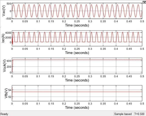
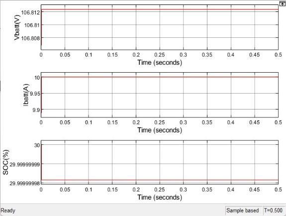
The performance of an enhanced EV charger utilizingaBLCukconverterwasexaminedduring steadystateconditions,asillustratedinFigs.7.17.2. Various parameters, including mains voltage, mainscurrent,batteryvoltage(Vbatt),andbattery current(Ibatt),wererecordedduringtheconstant current(CC)chargingmode.FromFig.7.1,itcanbe observed that the charger draws a unity power
factor(PF)currentfromthemains,whichalignsin phase with the supply voltage. This confirms the improved power quality (PQ) performance of the charger, complying with the recommended PQ regulations.
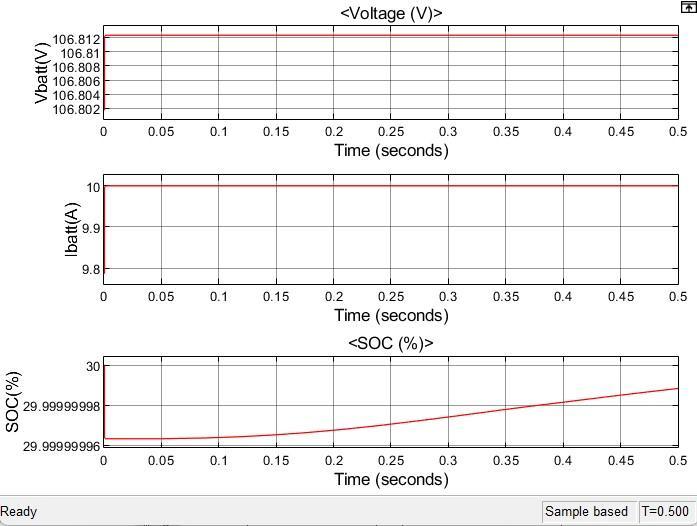
Furthermore,Fig.7.1demonstratesthattheoutput voltageoftheBridgelessCukconverterisprecisely controlledataconstant400V,whichisnecessaryto supplypowertotheflybackconverterattheoutput. The output of the flyback converter is effectively regulated at 53V, slightly higher than the battery voltage.Thisensuresthatthebatteryconsistently drawsacurrentof10Afromthemainsthroughout theentireCCchargingprocess,asindicatedbythe batterycurrent.
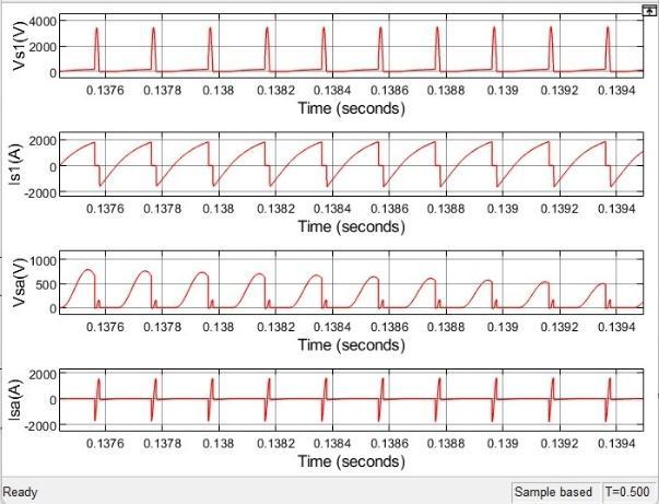
InFig.7.4,thevoltageandcurrentstressonthePFC switches S1 and S2 during their respective half cycles are depicted for the BL Cuk converter. The recordedswitchcurrentwaveformsclearlyindicate that the switch currents, Is1 and Is2, do not contribute to any circulating current flow during boththepositiveandnegativehalfcycleoperations. ThisobservationvalidatesthattheproposedBLCuk converter does not have any circulating current passing through the input inductors Li1 and Li2. This is due to the absence of interconnection between intermediate capacitors, as mentioned earlier in the topological discussion, which eliminates the formation of a circulating current loop.Asaresult,thechargerexperiencesreduced circulatingpowerloss,leadingtoanimprovement inconverterefficiency.InFig7.5,wecannoticethat theinputcurrentwithTHDof46.43%
B. SEPICPFCBasedEVBatteryCharger
Performance of Charger at Steady State
A. PerformanceofImprovedCharger
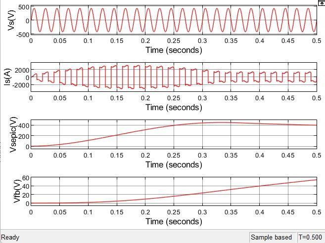
The experimental findings regarding the enhanced efficiency of an electric vehicle (EV) chargerutilizingaSEPICconverteraredepicted inFigures8.1and8.2.InFigure8.1,theoutput voltage Vsepic of the SEPIC converter is carefully controlled and maintained at a constant value of 400V, as indicated in accordancewiththeconverter'sspecifications.
ThewaveformdiagramspresentedinFigure8.2 illustratethevoltage(Vbatt)andcurrent(Ibatt) ofthebattery,correlatingwiththeinputvoltage (Vs) and current (Is). It is evident from the graphs that the battery is undergoing a chargingprocesswithaconsistentcurrentflow of 10A. The enhanced power factor (PF)
operation is distinguished by a synchronous currentdrawnfromthepowersupply,resulting inanin-phaserelationshipbetweenthesupply currentandvoltage.
B. PerformanceofSEPICConverter:
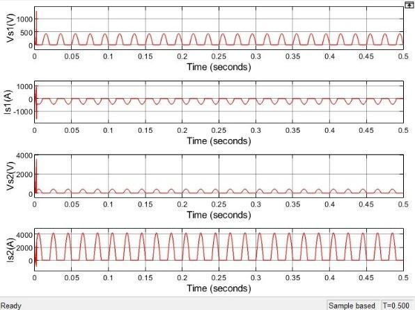
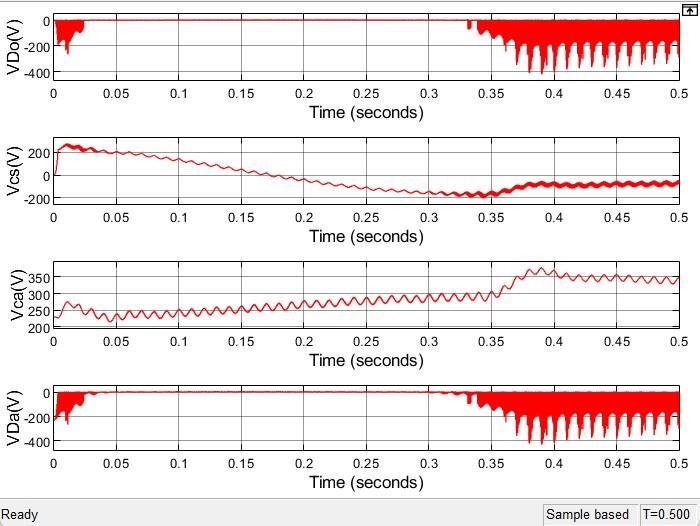
The steady-state performance of the high voltagegainoperationoftheSEPICconverterin discontinuous conduction mode (DCM) has been successfully validated. Figure 8.3 illustrates the voltage and current levels experienced by the main and auxiliary semiconductor devices during power factor (PF)correction.Uponcloserexaminationofthe switchvoltage,itcanbeobservedthatswitches endureavoltagestressof600V.Theincreased voltagegainoftheconverterleadstoareduced dutycyclerequirementforachievingthesame DC-link voltage of 400V, resulting in lower switch voltage stress. Similarly, the voltage stress across the auxiliary diode Da can be observedinFigure8.5.
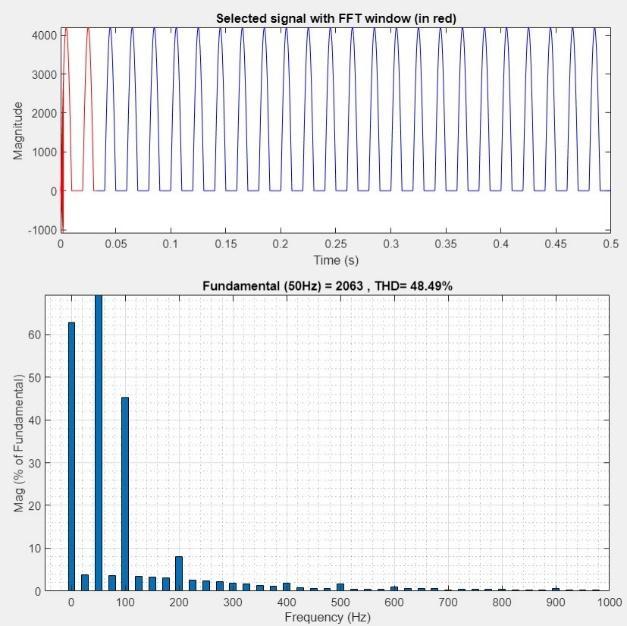
Thevoltageandcurrentlevelsobservedinthe main and auxiliary semiconductor devices, as well as the output inductor current (ILo) in DCMandinputinductorcurrents(IL1,IL2)in CCM,asdepictedinFigure 8.4,remainwithin justifiablelimits.Notably,whenexaminingthe zoomedwaveformsoftheswitchesanddiodes voltage,itbecomesapparentthattheconverter exhibitsinherentsoftswitchingcharacteristics duetotheselectionofDCMoperation.Thepeak current stress experienced by the output inductor reaches 2000A, which confirms the appropriateselectionoftheoutputinductance value. Additionally, Figure 8.5 provides a comprehensive illustration of the continuous voltageacrosstheenergytransfercapacitances (CsandCa)throughoutonecompleteswitching cycle. In Fig 8.6, we can notice that the input currentwithTHDof46.89%

Sourcesidequantities(Vac,Iac),DClinkvoltage ofBridgelessCukconverter(Vcuk),flybackconverter outputcharacteristics(Vfb)
Switchvoltagesandcurrentswaveforms (Vs1, Is1,Vs2,Is2)ofswitchesS1andS2ofBridgelessCuk ConverterBasedEVBatteryChargerrespectively

Batterysidequantities(Vbatt,Ibatt,StateOf Charge)ofBridgelessCukConverterBasedEVBattery Charger

THDofinputcurrentofBridgelessCuk ConverterBasedEVBatteryCharger
Inductorcurrents(ILi1,ILi2)andCapacitor voltages(Vc1,Vc2)ofBridgelessCukConverterBasedEV BatteryChargerinpositiveandnegativehalfcycles respectively
Sourcesidequantities(Vs,Is),DClinkvoltage ofSEPICPFC(Vsepic),Isolatedconverteroutput characteristics(Vfb)

5.CONCLUSION

BoththeBridgelessCukConverterwithFlybackConverter andtheSEPICPFCConverterwithFlybackConverteroffer power quality improvement in EV chargers, but they also comewiththeirownsetofdisadvantages.

Parameter Bridgeless Cuk Converter + Flyback Converter
SEPIC PFC + Flyback Converter
PowerFactor UnityPower Factor(0.999) UnityPower Factor (0.976)
Total Harmonic Distortion Lower(46.89%) High (48.49%)
Voltage Stress acrossSwitches Low(450V) Moderate to High(600V)
Current Stress on Switches Low(750A) Moderate to High(1600A)
Voltage across Capacitors 850V 350V
CostandWeight Less More Complexity High Low
The Bridgeless Cuk Converter combination demonstrates severaladvantages,includingahigherpowerfactorof0.999 compared to 0.976 for the SEPIC PFC combination. Moreover, the Bridgeless Cuk Converter combination exhibits lower total harmonic distortion (THD) at 46.89% comparedtothehigherTHDof48.49%forthe SEPICPFC combination i.e., the Bridgeless Cuk Converter combined withtheFlybackConverterhasapproximately3.3%lower THDcomparedtotheSEPICPFCcombinedwiththeFlyback Converter.
TheBridgelessCukConvertercombinationexhibitsalower voltage stress across switches of 450V compared to the moderate to high voltage stress of 600V in the SEPIC PFC combination. This indicates that the Bridgeless Cuk Convertercombinationimposeslessstrainontheswitches, potentiallyleadingtoimprovedreliabilityandlongevity.
Furthermore,thecurrentstressonswitchesislowerinthe BridgelessCukConvertercombinationat750A,whereasthe SEPICPFCcombinationexperiencesahighercurrentstress of 1600A. This highlights the Bridgeless Cuk Converter combination'sabilitytohandlelowercurrentlevels,which cancontributetoreducedlossesandincreasedefficiency.
Regarding voltage across capacitors, the Bridgeless Cuk Convertercombinationoperatesatahighervoltageof850V compared to the lower voltage of 350V in the SEPIC PFC combination. This higher voltage provides the Bridgeless
Cuk Converter combination with greater energy storage capabilitiesandpotentialforimprovedperformance.
Additionally, the Bridgeless Cuk Converter combination achieveshigherefficiency,whilebeinglesscostlyandlighter. However, it is worth noting that the Bridgeless Cuk Convertercombinationismorecomplexintermsofdesign Overall, the Bridgeless Cuk Converter combined with the Flyback Converter outperforms the SEPIC PFC combined withtheFlybackConverterintermsofpowerfactor,THD, stresslevels,efficiency,cost,andweight.
6. REFERENCES
[1] C. Chan and K. Chau, “Power electronics challenges in electricvehicles,”inProc.IEEEIECON’93.,pp.701–706.
[2] Limits for Harmonics Current Emissions (Equipment current ≤ 16A per Phase), International standards IEC 61000-3-2,2000.
[3]BhimSingh,BrijN.Singh,AmbarishChandra,KamalAlHaddad,AshishPandey,andDwarkaP.Kothari.“Areviewof single-phase improved power quality AC-DC converters,” IEEE Transactions Industrial Electronics, vol.50, no. 5, pp.962-981,July2003.
[4] L. Huber, Y. Jang, and M. Jovanovic, “Performance evaluation of bridgeless PFC boost rectifiers,” IEEE Transactions Power Electronics, vol. 23, no. 3, pp. 1381–1390,May2008.
[5] B. Zhao, A. Abramovitz and K. Smedley, “Family of bridgeless buck-boost PFC rectifiers,” IEEE Transactions PowerElectronics,vol.30,no.12,pp.6524-6527,Dec.2015.
[6]D.S.L.Simonetti,J.Sebastian,F.S.dosReisandJ.Uceda, “Design criteria for SEPIC and Cuk converters as power factorpreregulatorsindiscontinuousconductionmode”in Proc. International Conference on Industrial Electronics, Control, Instrumentation, and Automation, 1992, pp. 283288vol.1.

[7]A.A.Fardoun,E.H.Ismail,A.J.SabzaliandM.A.Al-Saffar, “New Efficient Bridgeless Cuk Rectifiers for PFC Applications,”IEEETransactionsonPowerElectronics,vol. 27,no.7,pp.3292-3301,July2012.
[8] T. J. Liang, K. H. Chen and J. F. Chen, “Primary Side ControlForFlybackConverterOperatinginDCMandCCM,” IEEETransactionsPowerElectronics,vol.33,no.4,pp.36043612,April2018.
[9]K.Yao,X.Ruan,X.MaoandZ.Ye,“Variable-Duty-Cycle ControltoAchieveHighInputPowerFactorforDCMBoost PFC Converter,” IEEE Transactions Industrial Electronics, vol.58,no.5,pp.1856-1865,May2011.
[10]SAEElectricVehicleandPlug-inHybridElectricVehicle ConductiveChargeCoupler,SAEStd.J1772,2010.

[11] Kushwaha, R., & Singh, B. (2018). A Power Quality ImprovedEVChargerwithBridgelessCukConverter.2018 IEEEInternationalConferenceonPowerElectronics,Drives andEnergySystems(PEDES).
[12]Kushwaha,R.,&Singh,B.(2019).AnImprovedSEPIC PFC Converter for Electric Vehicle Battery Charger.2019 IEEEIndustryApplicationsSocietyAnnualMeeting.
