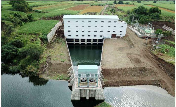
"Design Criteria of Lift Irrigation Scheme"
 Kiran M. Jadhav*, Dr. S.P.Chavan 2
1Mr.K.M.Jadhav (M.Tech design Engineering ,Deputy Engineer, water Resources Department, Gov. of Maharashtra, India.
2Dr.S.P.Chavan, Professor Department of Mechanical Engineering, Walchand College of Engineering, Sangli, India ***
Abstract: Irrigation is an essential part of farming. Maharashtra government try to develop best irrigation network for irrigation of all region. But with the help of Gravity fed Canal network it is not possible to provide irrigation at remote area. In now days Lift Irrigation Scheme ( LIS) plays an vital role for irrigation of this remote area. In LIS water has lifted from source i.e. Dam, lake or river to the delivery chamber with the help of pumps and distributed to all command area with canal network. The success of LIS is mainly depend on accurate planning, designing and selection of pumping equipment's. For designing of any LIS , design and selection of pump , R.L. of bottom of sump, R.L. of M.D.D.L. in the sump , P.O.L, Static Head , Diameter of rising main etc. all these parameters should be considered . In this paper we will get clear idea about design of Lift Irrigation Scheme (LIS) and clear idea about what care should be take while designing of LIS.
Key Words: LIS, M.D.D.L, P.O.L , Pump
1. Introduction
LiftIrrigationschemeisusedforsupplyofwaterto remoteareawheregravityfedcanalnetworkisnotwork.In LIS pumping stations are used to lift the water to appropriateheightwithrequiredpressure.Inthepumping stationsPumpplaysavitalrole.Pumpis'heart'ofallsystem as it converts mechanical energy to hydraulic energy. For properworkingofLISwithhighefficiencyutmostcaremust betakenwhileplanning,selecting&designingofpumping equipments & accessories. The following points must be consideredtodevelopanewLIS.[1]
i) Selection of Pumps. ii ) Intake Design iii) Layout of the pumphouse.iv)Selectionofvalvesv)Selectionofmotorsvi) Selection of Starters vii) Selection of capacitors viii) Selection of Control Panel ix) Selection of HT cables x) Selectionofauxiliarytransformersxi)Deliverypipe&Rising main.
2. Selection of Pumps:
Thebasicdatarequiredfortheselectionofpumpfor LISiscollectedfromcivilwing.Theyprovidethisdataasper actualsitecondition.BasicDatarequiredforCalculationof PumpParameters:
2.1 Discharge:
i) Maximum discharge required ii) Minimum dischargerequired
2.2 Various Control Levels:
i)NormalWaterLevel ii)MDDL(Minimum DrawDownLevel)
iii)MaximumWaterLevel iv)HighFloodLevel
v)DischargePointlevel vi)SumpFloorlevel
vii)Motorfloorlevel viii)Valvefloorlevel
2.3 Rising main
i)RisingmainDiameterandThickness ii)Rising mainLength
1) Following tabel gives the selection of pumps accordingtotheuseofapplicationandaccordingto variousduties:
Table 1.1: Selection of Pump for LIS
3. Pump Parameters Calculations
3.1
Determination of Pump Horse Power
P= ………… (Eq.1)
Where,P=Horsepowerrequiredtodrivethepump
Q=Dischargeperpump /Hr
H=Totalheadinmeters
W=SpecificWeightofliquidforwater1000 Kg/
As the pump efficiency for centrifugal pump is found optimumintherangeof2000-3000USunits[1]
3.2 Determination of Total Head
TotalHead=StaticHead+DynamicHeadinMWC
DynamicHead=FrictionalHead+VelocityHead
a)StaticHead =DischargeLevel–PumpoperatingLevelor NormalWaterLevel
Assumption to calculate static head – i) Discharge level is centrelineofrisingmainatdeliverypoint.
ii) Pump Operating Level (POL) = MDDL + (2/3)(FRL –MDDL) ………… (Eq.2 )
where–MDDL=Minimumdrawdown level
FRL=FullReservoirlevelinpumpsump
3.3 Determination of Dynamic Head
InDynamicHeadLossincludesFrictionalandVelocityHead loss
a) Frictional Head Loss:
When Fluid is flowing through pipelines there is friction occursbetweenthefluidandwallsofthepipelineandsome headlossoccursiscalledfrictionalheadloss.
To calculate frictional head loss in rising main modified Hazen'sWilliamsformulaisused[3]
Hf1=Lx(Q/Cr)1.81/994.2(D)4.81 …………………….(Eq.3)
Hf1=frictionalHeadLossinRisingmain
L=Lengthofrisingmaininmeters
Q=Dischargein /sec
Cr=Piperoughnesscoefficient
D=PipediainMeter
b) Head Loss due to Bends and Valves in rising main –HF2 [4]
Hf2=(KnV^2/2g)inMWC………………………… (Eq.4)

Where,
n=Noofvalvesorbends
V=Velocityinrisingmaininm/s
g=gravitationalacceleration=9.813/s^2
K=Constant
c) Velocity Head Loss (Hf3)
Hf3=(V^2/2g)MWC …………………………….(Eq.5)
Where,
Hf3=VelocityheadlossatExitMWC
V=Velocityinrisingmainm/s
g=gravitationalacceleration=9.813/s^2
3.4 NPSHA calculation :
NPSHA stands for Net Positive Suction Head. To avoid cavitationattheinletofthepump,pumpsystemhastobe designedsuchthatpumpsuctionwillhaveadequateenergy. Thisenergymadeavailablefromatmosphericpressureand water head available on pump suction side. NPSHA is calculatedasbelow-
NPSHA @ NWL = (Patm –Pvap +- Submergence ………………………….(Eq.6)
=(Patm–Pvap+-(NWL–SBL–Impellereye clearanceinMWC)
NPSHA@MDDL==(Patm–Pvap)+-Submergence
=(Patm–Pvap)+-(MDDL–SBL–Impeller eyeclearanceinMWC)
Where,Patm=atmosphericpressure
Pvap=VapourPressure
ImpellerEyeClearance=2D(D=BellmouthDia.inm)

ToavoidthecavitationatsuctionofpumpNPSHAmustbe greaterthanNPSHR(NetPositiveSuctionHeadRequired) [1]
3.5 Thoma's Cavitation Parameter:
Ifthepressureatanypointinsidethepupdropsbelowthe vapour pressure of the liquid at correspondent temp. the liquid starts vaporises and vapour bubbles forms. These cavitiesorvapourbubblescarriedoutinsidetheimpeller,as cavitiesmaycollapsewithtremendousimpactonsidewall ofthepump.Thisphenomenoncalledcavitation.Thiscauses NoiseandVibrationinsidethepump.TheScientistnamed ThomadevelopedaequationtopredictCavitation.[2]
i)ThomaAvailable
a)Thomaavailable@NWL=(NPSHA@NWL/Totalhead perstage)
b) Thoma available @ MDDL = ( NPSHA @ MDDL / Total headperstage)
ii)ThomaCritical
ThomaCritical=6.3x10^-6(Nq)^4/3 ……………. (Eq.7)
Where,Nq=PumpSpecificSpeedinUSunits
ToavoidcavitationinsidethepumpThomaavailablemust begreaterthanThomaCritical.
3.5 Pump Specific Speed
SpecipicSpeedofapumpinUSunitisspeedofgeometrically similar pump which delever 1 gallon of water per minute throughheadof1feet
Nq= …………………………………………. (Eq.8)
Nq=PumpSpecificSpeedinUSunit
N=ShaftRPM
Q=DischargeofPumpgallons/min.(fordoublesuctiontake Q/2)
SuctionSpecificSpeed(Ns)
Ns= ……………………………. (Eq.9)
N=ShaftRPM(SlipRPM)
Q=Dischargeofpumpingallon/min.
4 . Pump Design
4.1 Design of Bell Mouth
Bell mouth id fitted below the pump impeller to havestreamlineflowtothepumpandtoavoidseparationof flowwithminimumloss.[3]
D=Diameterofbellmouthcalculatedasbelow
D= …………………………………………. (Eq.10)
Where,
Q=Pumpdischargeinm^3/sec
D=Bellmouthdiameterinmeter
V=Velocityatbellmouth(i.e.1.5m/secasperwatersupply manual)
4.2 Design of Column Pipe Diammeter
Columnpipeispipethroughwhichliquidgoesup.ForV.T Pump
Q=( x[(Dc)^2-(Do)^2]xV ………………………….(Eq.11)
Where,
Dc=Insidediaofcolumnpipe
Do=Outsidediaofshaftenclosingtubeinmeter
V=Velocityinm/seci.e.upto2m/sec
4.3 Design of Column Pipe Thickness
Columpipewillworkasaclosedpressurevesselatshutoff head,hencethicknessofcolumnpipedesignedconsidering columnpipeasaclosedpressurevessel.
Tc= +c …………………………………………. (Eq. 12)
P=DesignPressureincolumnpipekg/cm^2
Pdesign=(1.5xShuttofheadinMWC/10)Kg/cm^2
Dc=InsideDiaofcolumnpipeinmm
F = Allowable safe stress for column pipe material in kg / mm^2

J=Weldingfactor0.7
C=corrosionallowanceKept1.5mm
4.3 Design of Delevery Pipe Diameter (Dd)
Q= x(Dd)^2xV ……………… …. (Eq.13)
V=Velocityindeliverypipeinm/sec.shouldbebelow2.5 m/sec
4.3 Design of line shaft Diameter

Lineshaftconnectstheheadshaftofmotortotheimpeller shaftofthepump.
Td= +C
Where,
P=MotorpowerinKw
…………………….(Eq.14)
N=ShaftRPM(SlipRPM)
F=Shaftstressoflineshaftmaterialkg/cm^2
Dl=Diameteroflineshaft
C=Corrosionallowance(kept3to4mm)
5. Conclusion:
Fromabovecasestudywecanconcludedthatwhiledesign ofaLISthereisneedtobetakecareofsomanyparameters. Selection and design of pump is main part in LIS. While selection and design of pump for LIS following conditions mustbefullfilled.
i)Whenonlineboostingistobedonethenhorizontalsplit casecentrifugalpumpsareused.
ii) When there is large variations in suction level Vertical Turbine pumps are selected. VT pump requires less floor spaceandCompactdesign.
iii)PumpSpecificSpeedshouldbeinrange2000-3000US unitsformaximumpumpefficiency.
iv)SuctionSpecificspeedshouldbelessthan8500USunits forgivenspecificspeed.
v)NPSHAshouldbegreaterthanNPSHRtoavoidcavitation. NPSHAisatleast0.5MWChigherthanNPSHR.
vi)ToavoidcavitationThomaavailablemustbegreaterthan ThomaCritical.Thomaavailabledependsonsiteconditions and Thoma critical depends on Pump design and Pump Specifcspeed.Sowhiledesigningofpumpthiscriteriamust befullfilled.
vii)Velocityatbellmouthmustbelessthan1.5m/sec.
vii)Velocityinthedeliverypipemustbelessthan2.5m/sec.
6. Acknowledgement:
I would like to thanks Water Resource Department for providing data regarding LIS. I would like to extent my sincere thanks to HOD and all faculty members of DepartmentofMechanicalEngineering,WCE,Sanglifortheir valuableadviceandcontinuousmotivation.

7. References
Referencetoajournalarticle:
[1] Mankikaran, Pumping YantraSamugri second edition, Published By Chief Engineer Water Resource Department Nashik2008.
[2]IgorJ.Karassik,etal.,“Pump Hand Book,”TheMcGraw Hill3rd edition2001.

[3]BansalR.K., “Fluid Mechanics and Hydraulic Machines,” Laxmi Publications Pvt. Ltd. 6th edition 1997, PP. 10651113.

[4]Manualofwatersupplyandtreatment(CPHEEO1999)
BIOGRAPHIES
Mr K.M. Jadhav,(M Tech Design Engineering)workingasaDeputy Engineer, Water Resources Department Government of Maharashtra.
