Design of Integrated Generator-Rectifier System to Determine the Maximum Power Point Tracking of Wind Turbine.
 J. Mahadeshwan Nayak*, Dr. M. Sushama**
*(M. Tech, Department of Electrical Engineering, JNTUH University College of Engineering, Hyderabad, India, **(Professor, Department of Electrical Engineering, JNTUH University College of Engineering, Hyderabad, India, ***

Abstract - Offshore wind turbines are widely favored for their higher energy generation capabilities compared to onshoreturbines.Additionally,theysupportgoodweatherand aquatic conditions. The need for effective power conversion technologiesmakesit difficult tomeetanaggressiveLevelized Cost of Energy (LCOE) objective for offshore turbines. A combination system that combines a Permanent Magnet SynchronousGenerator(PMSG)witharectifiersystemcan be used to overcome this problem. An active rectifier and numerous passive rectifiers make up the rectifier system. However, obtaining the requisite maximum power output is challenging due to the presence of uncontrollable passive rectifiers. This research suggests a unique Fuzzy Logic Controller (FLC)-based Maximum Power Point Tracking (MPPT) architecture to address this problem. The proposed methodenablestheacquisitionofmaximumpower(MPPT)by using FLC to analyze the d-axis current generated. Utilizing MATLAB/Simulink,theproposedmethod'sefficacyisassessed.
Key words: FLC, MPPT, Rectifiers, and Offshore Wind Turbines
1. INTRODUCTION
Themovementofairorgasesfromoneplacetoanotherthat results from variations in pressure and temperature is knownaswind.Utilisingthesewindssuccessfullyallowsfor the production of wind energy. Modern methods for harnessingwindenergyaselectricityhavebeenintroduced inrecentyears.Dependingontheregion,therearetwotypes of wind energy: onshore wind energy and offshore wind energy.Onshorewindenergyinvolvesproducingelectricity fromwindturbinesthataresituatedonland.Ontheother side,offshorewindenergyisproducedbywindthattravels acrosstheocean.Typically,offshorewindenergyiscreated intheocean.
Windenergyisaclean,renewableenergysourcethathasa lotofpotentialfordiversifyingtheworld'selectricitysupply. Itisincreasinglybeingusedasarenewableenergysource.In comparisontoonshorewindenergy,offshorewindenergy offerstheadvantageofamorereliableandpowerfulwind spectrum.Furthermore,becauseoffshorewindsaremilder, turbinefatigueisreducedanditsusablelifeisincreased.The great potential of this renewable energy source is demonstratedbytheincreasinginstalledcapacityofoffshore
wind turbines. Offshore wind turbines can now generate electricityatalevelizedcostthatiscompetitivewithonshore alternatives.
ThepoweroutputsoftheGamesa10X[3]andHalideX[4] wind turbines are around 10–12 MW. The constraints of present converter topologies make it difficult to create dependable electromechanical power conversion systems forthesehigh-power-density,energy-efficientturbines.The primary difficulties are brought on by power electronics switches' low voltage/current ratings and increasing switching losses [5]. Currently, two-level pulse width modulation (PWM) and neutral-point-clamped converters arefrequentlyused.Thesecondstrategyischosenbecauseit provides a most simple design and operating approach.
The architecture for tracking power points comprises connecting power electronic devices in series and/or paralleltomanagemanymegawattsofpower.However,the unequaldistributionoflossesacrosstheswitchesinthese configurations makes them frequently unreliable, which increases failure in hotspot locations. A neutral-pointclamped topology is used to solve this problem, greatly reducing the peak voltage that may be delivered to each switch[6].
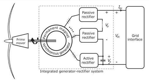
Reducingthepowerratingofindividualpowerconvertersis thegoalofimplementingamultiportgenerator.Utilizingjust active rectifiers, which convert AC to DC, is one strategy. Permanentmagnetsynchronousgenerators(PMSGs)-based integrated generator-rectifier systems are a possibility, as depicted in Fig. 1 [7]. Rectifiers fitted to each port in
multiport PMSGs transform the kinetic energy from the turbine shaft's rotation into alternating current power. A high-voltagedirectcurrent(DC)busisbuiltbyjoiningthe rectifieroutputsinseries.Inthisdesign,justasmallportion of the entire voltage on the DC bus is present across each rectifier. A viable alternative is the combined generatorrectifiersystembasedonapermanentmagnetsynchronous generator (PMSG), as shown in Fig. 1 [20], [21]. In this system,amultiportPMSGtransformsthemechanicalenergy from the turbine shaft into AC electrical energy. For the conversion of AC to DC, a passive or active rectifier is attachedtoeachportofthePMSG.Areasonablyhigh-voltage DC bus is created by series-connecting the rectifiers' DC outputs. Only a small percentage of the overall DC-bus voltageishandledbyeachrectifier.Passiverectifiersprocess 60% of the total power as a result, which, under rated workingconditions,resultsina47%reductioninconversion loss Theactiverectifier'ssizehasbeendecreased,whichhas enhanced the system's overall power density and dependability.
Itissuggestedthatacontrolframeworkbeusedtoachieve maximum power point tracking (MPPT) by establishing a linkbetweenthetotalDCpowerandtheactiverectifier'sdaxis current. The use of uncontrolled passive rectifiers is replaced by this control system. To accomplish maximum powerpointtracking(MPPT)andenhancetheeffectiveness ofwindenergyconversionsystems,acontrolledframework isintroduced.Inthisframework,fuzzylogic(FL)controllers areusedtoanalyzethed-axiscurrentoftheactiverectifier. FLC offers an inference mechanism that delivers flexible valuesforaccomplishingMPPTincontrasttoconventional Proportional-Integral(PI)controllerswithconstantvalues. Thismakesitpossibletogeneratemoreelectricityandmore preciselycaptureallofthewindenergythatispresent.An advantageous option for wind power applications, the integrated rectifier system utilizing FLC contributes to a competitivelevelizedcostofenergy(LCOE).Threesections makeupthepaper.TheMPPT-basedpowerflowregulation for a combined generator-rectifier system is covered in SectionII.ThesimulationfindingsinSectionIIIshowhow successful the suggested control strategy is. Section IV, whichsummarizestheresultsanddiscussespotentialfuture studyoptions,bringsthepapertoaclose.
2. The Integrated Generator-Rectifier System's Power Flow:

Aframeworkforcontrollingthepowerflowinthecombined generator-rectifier system has been created during this stage.assumingthatahard-wiredconnectionconnectsthe system'sDCoutputtoaDCgridinterface.Thispresumption hasbeenshowntobetrueforbothACandDCgrids[5].The converteronthegridsideofanACgridcontrolstheDCbus, which acts as an interface. In contrast, the DC side grid
converter in a DC grid is in charge of managing the DC voltage[9].
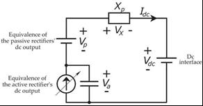
A simplified version of the equivalent circuit for the generator-rectifier system is shown in Fig. 2. In the combined generator-rectifier system, Vp stands for the voltagegeneratedbythepassiverectifiers.Thegenerator's rotational speed and this voltage are directly inversely related. An Xp-valued commutation reactance is linked in serieswithaVp-valuedvoltagedividertoreducetheoutput voltage ripples of the passive rectifiers. It is possible to effectivelydisregardtheoverallripplesintheoutputvoltage ofthepassiverectifierbymaintainingaphaseshiftbetween variousACports.
Bydeductingtheoutputvoltageofthepassiverectifier,Vp, fromtheconstantgridinterfacevoltage,onemaycalculate theDC-sidevoltageoftheactiverectifier,denotedasVa.The activerectifierextractscontrollablepowerfromthesystem intheformofacontrollablecurrentsource.Thecurrenton the DC-side is represented by this controlled power. The current obtained from the active rectifier determines the total power flow into the DC bus due to the series connection.
Considering a total of k three-phase AC ports, the passive rectifiersforaPMSGarefedvia(k-1)portswithoutoutput filtercapacitors.Everyπ/3radian,thevoltageripplepeaks. TheDCoutputscanbelinkedinserieswithanappropriate phase shift of π/3(k-1) radians to lessen voltage ripples. When(k-1)passiverectifierswithaphaseshiftofπ/3(k-1) radiansareusedinasystem,thevoltagerippleisdecreased.
ItispossibletoattaintheDCoutputvoltageof(k-1)passive rectifiersatfrequencyIdcbytakingintoaccountaconstant DC bus current and little voltage ripple. It is important to notethatariseinthenumberofACportsdecreasesvoltage ripples,albeitataslowerrate.Asimilarstrategyisusedto employphaseshiftingtransformersandmulti-pulsediode rectifiers to further reduce harmonic distortion in highpower drives. The phase current commutation switching
period is estimated to be less than one-sixth of the entire time length due to the assumption that the synchronous inductance, represented as "L," is relatively small. This circumstanceisequivalenttoaconventionalsix-pulsediode bridgerectifieroperatinginthefirstmode.Thecomparable seriesresistanceforeachportperphaseisdenotedbythe letter"R."Electricalfrequencyaffectsthebackelectromotive force,orE(w).
Thed-axiscurrentoftheactiverectifierandthepoweratthe DCbusaresignificantlycorrelated.
At the output DC side voltage of the passive rectifier, the resistanceperphase,synchronousinductance,andDCbus currentarecollectivelyreferredtoasVx.Itisaffectedbythe backelectromotiveforce(EMF),whichisrepresentedbyEo and is the rated line-to-neutral peak of each alternating currentport,aswellastheratedelectricalfrequency(fo)of eachACport.
4. Power-Flow Control Using Active Rectifiers:

It is done to calculate the DC bus power from the active rectifier'sACsidecurrent.Theactiverectifier'sconversion lossesarenottakenintoaccountinthiscomputation.Both theACandDCsideshaveequal power.
Itcanbeseenfromthepreviouslydescribedequation(6)that the active rectifier's d-axis current significantly affects the regulationoftheDC-buspower.Thepowerdrawnfromthe turbinecanberegulatedequivalentlybyalteringthed-axis current. In other words, controlling the d-axis current enables efficient control of the turbine's power flow and utilization.
Vastandsfortheactiverectifier'sdc-sidevoltage,whileIsd stands for the AC side's d-axis current component. It is crucial to understand that phase-A's greatest back electromotiveforce(EMF)linesupwiththed-axis.
Va=Vdc-Vp+Xp*Idc
Inthisequation:

Va represents the dc-side voltage of the active rectifier.
Vdcrepresentsthedcvoltage.
Vprepresentsthevoltagedrop.
Xprepresentsthereactance.
Idcrepresentsthedccurrent.

Currentofdccurrentisgivenby
Figure3'sdepictionofthecascadedesignisusedtocontrol the power flow. The active rectifiers' d-axis and q-axis currentsarecontrolledbycurrentcontrollersintheinner loop.Theq-axiscurrentregulatesthepowerfactorwhereas thed-axiscurrentcontrolsthepowerflow.Thefuzzylogic controller (FLC) used by the outer loop power controller modifies the d-axis current signal in order to send the desired reference power (P*dc) to the DC-bus. The generator'srotationalspeedservesastheFLC'sinput,and theMPPTalgorithmgeneratesthepowersignal.Theactive rectifierobtainsapowerfactorof1atnocurrentontheqaxis. The dynamics of the AC current at the port in the reference frame can be used to model the current controllers.Thespecificcontrolmethodanddesignselected for the current controllers will determine the modelling equations.
Theequationdemonstrateshowequations(4)and(5)can beaddedtoequation(1)toproducethepowerattheDCbus.


In the example, Vrd and Vrq stand for the input d-axis voltageandq-axiscurrent,respectively.Inphase-A,thedaxisalignswiththemaximalbackelectromotiveforce(EMF), and the q-axis is 90 degrees in front of the d-axis. A PI (proportional-integral) controller that integrates feedforward terms to produce voltage along the d-axis is implementedusingequation(7).

Equation(8),whichisthesamemethodusedforthed-axis currentcontroller,canbeutilisedtocreatetheq-axiscurrent controller.Withrespecttotheq-axisreferencecurrentI*qs, KpqstandsfortheproportionalgainandKiqfortheintegral gaininEquation(8).Equation(6)usestheknownvaluesofL (inductance) and R (resistance) to directly calculate the power demand based on the d-axis current command. Parametricuncertaintyinpowerflowcontrolisdecreased throughtheimplementationofanouter-loopPIcontrol.The aboveinformationshowsthisouter-loopcontrolmethod.

(i) Fuzzification: Using a collection of membership functions (MFs), crisp values are transformed into fuzzy valuesinthefuzzificationstepofthefuzzylogiccontroller. Themembershipfunctionsspecifythelevelofaparticular input'soroutput'smembershipindifferentfuzzysets.Inthis instance, Figures 5, 6, and 7 show, respectively, the membershipfunctionsforthepowererrorinput,changein powerinput,andoutput.Themembershipfunctionsgivethe inputs and outputs a linguistic representation, enabling a more flexible and understandable control system. The controller can deal with the uncertainty and imprecision presentinreal-worldsystemsbyfuzzifyingthecrispinputs.

The terms Kpp and Kip stand for the proportional and integral gains, respectively. Based on the difference in inaccuracybetweenthereferencesignalandthemeasured signal,theproportionalgain,Kpp,decideshowthecontroller will react. In order to eliminate steady-state errors and regulatethesystem'sresponsivenessovertime,theintegral gain,Kip,isused.Theouter-loopPIcontrolmaysuccessfully control the power flow and achieve the required system performancebymodifyingthevaluesofKppandKip.


5. Fuzzy Logic Controller System:
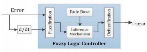
Byusingathoughtprocessandrule-basedtechniques,fuzzy logic controllers are in fact regarded as effective tools for boosting the performance of electrical equipment. Fuzzy logiccontrollersincludeaninferencesystemthattakesinto account a variety of feasible values, in contrast to PI controllerswheretheproportionalandintegralgainvalues are fixed. Compared to conventional PI controllers, this dynamic technique enables greater accuracy and better powerflowmanagement[10].Thepowerreceivedthrough themaximumpowerpointtracking(MPPT)algorithmand thechangeinpowerarethetwoinputsusedinthespecific instance of the aforementioned fuzzy logic controller. The controllerthenoutputsasignalthatmodulatesthecurrent along the d-axis. In order for the fuzzy logic controller to function,fourcrucialstepsmustbecompleted.
(ii) Set of ambiguous guidelines: FLC-basedpowerflow regulationbasedonerroranditsvariationinpowererror.

Table I: RulesTable
By using a rule base and taking into account both the
measured changes in the error and the conditions of the errordata,thepowerflowcontrolisdecided.Theprocedure is carried out by consulting Table 1, which includes the requiredinstructions.TheMinimum-Maximumfunctionis usedtocalculatetheoutput'sdegreeofmembership,which enables evaluation of the output's membership in each individualfuzzyset.
(iii) Fuzzy Inference System: Thefinalfuzzyvaluefrom thepreviousphaseissenttotheinferencemechanismstage, wheretheMamdanimethodisusedtoapplytheMinimumMaximum rule. The Fuzzy Logic Controller (FLC) uses the fuzzyrule-basedapproachtoguideitsdecisionsatthislevel. Thesefuzzy valuesareprocessed bytheFLC beforebeing sent to the defuzzification procedure for additional examinationandtransformationintocrispvalues.
(iv) Defuzzification: Inthisstage,thecentroidapproachis used to convert the fuzzy values produced from the fuzzy inference mechanism into crisp values, more especially current values. The crisp output value is precisely representedusingthecentroidtechnique,whichdetermines the fuzzy output membership function's centre of gravity. Theacquiredcurrentvaluescanbeusedforfurtheranalysis and control in the power flow system thanks to this conversion.
6. Representation of Maximum Power Point Tracking (MPPT) for Integrated Generator Rectifier System.
The MPPT method is used by the integrated generator rectifiersystemtomonitorthepeakpowerpoint.Thisstudy selectsthePowerSignalFeedbackcontrolapproachfroma range of alternatives. To maximise power extraction, it continuously monitors the power signal and modifies the operatingpoint.Itseekstotrackthemaximumpowerpoint and enhance system performance by utilising feedback loops.Thepeakpowerpointistrackedviathepowerblock diagram.Thealignmentoftheobtainedpowerwiththepeak power curve demonstrates successful MPPT at each generatorspeed.

Agraphofpowercurvesatvariouswindspeedsisshown. Themechanicalpowercurves'peakpointsareconnectedto create the maximum power curve, which has a maximum powerof11MW.


7. Simulation Results:
7.1 Controlling of Power Flow:
Fig 9. Three-portPermanentMagnetSynchronous Generatorsimulationmodel
Therelationshipbetweenthed-axiscurrentandtheDC-bus power, which includes the power electronics switching circuits, as described in equation (6), is illustrated by the simulationmodelinFigure9.Threevoltagesourceslinkedin serieswitharesistance(R)andaninductance(L)makeup the three-port PMSG theoretically. An external speed referencesignaldeterminesthevoltagesources'frequency (f) and amplitude (a). Connected to Ports I and II are uncontrolledthree-phasedioderectifiers.Tolessenvoltage rippleintheDCoutputsofthepassiverectifiers,thephase-A (andphase-Bandphase-C)voltagesarephase-shiftedby/6 electrical radian. Port-III is connected to active rectifiers, which are made up of IGBTs with a 2 kHz switching frequency. A DC bus is created by connecting the rectifier outputsinseries.ThegridconnectionisindicatedbytheDC busvoltageof5.7kV.

7.2 Maximum Power Point Tracking of DC-Bus Power:
ForMPPTcontrol,thesimulationmodelinFigure9isused. The generator provides the reference speed for the wind turbine,representedbythesymbolm.
=40(rad/s)andw=22(rad/s),itcanbeseenthattheripple factorgetssmallerasthePMSG'soverall powerrises.The obtainedripplefactorisbelowthepermittedthreshold.
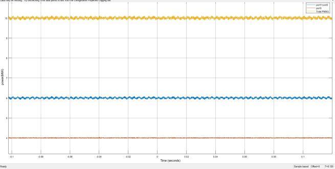
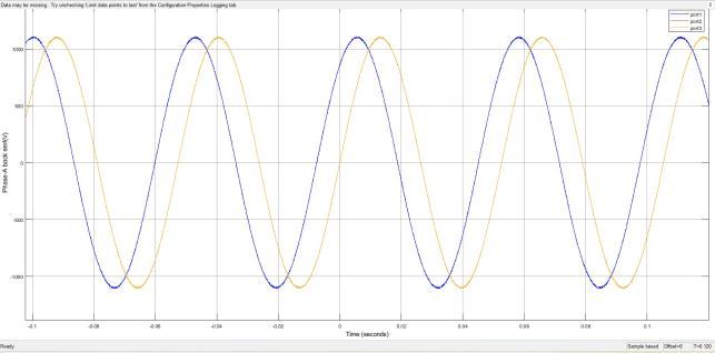
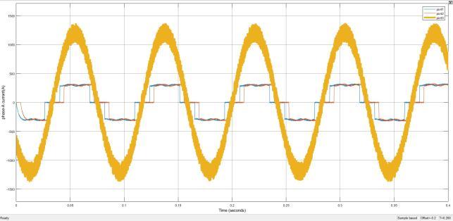
Fig. 10 At��=40��(������/��)thesimulationwaveformsareas follows: (a) Attheratedspeedofthegenerator,sinusoidal and phase-shifted back EMFs are observed. (b) The respectivecurrentsofphase-Aareshown. (c) Attherated speed,thePMSGdistributesinputpowerbetweentheactive andpassiverectifiers.
The wind turbine's moment of inertia, denoted as J, has a value of 28.7 × 10^6 ���� ∙ ��^2. In order to speed up simulation, the chosen value of J is 50 times smaller for simulationreasons[11].


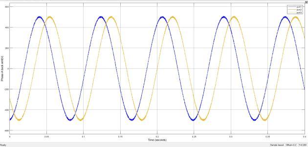
ThePhase-AbackEMFsofPorts1,2,and3atthespecified electrical frequency of 20 Hz are shown in Fig. 10(a). The Phase-AcurrentsofthethreeACportsforan11MWrated DC bus power are displayed in Fig. 10(b). Figure 10(c) illustratestheoverallinputpowerofthePMSG,whichwas calculatedbyaddingthepoweroutputsofallthebackEMFs. Similarvaluesatthelowestoperatingspeedareshown in Figs.10(d),(e),and(f).Whencomparingthetwospeedsatw
Fig.10 presents the simulation waveforms at �� = 22��(������/��)asfollows:(d) Attheminimumoperatingspeed, the back EMFs are equal to 55% of the rated speed back EMFs. (e) At the minimum operating speed, the phase-A currentsexhibitspecificpatterns.
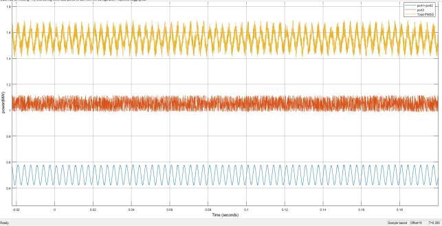
(f) Attheminimumoperatingspeed,theinputpowerofthe PMSGissharedbetweentheactiveandpassiverectifiers. 11.(a) 11.(b) 11.(c)
Fig.11 illustratesthewaveformsdemonstratingtheMPPT capabilities of the system:(a) At each wind speed, the turbinespeed(solidblueline)followstheoptimalspeedto generatemaximumpower.(b) ThepoweroftheDCbusand themechanicalpoweroftheturbineareplottedagainsttime, showingtheirrelationship.

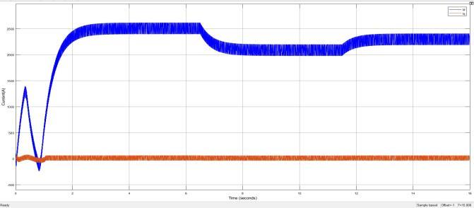
Whenthewindspeedreaches12m/s,theturbinebeginsto spinat55%ofitsratedspeed.Whiletheturbine'smaximum outputis 11MWatthisspeed,theDC bus power isjust 2 MW.AccordingtoFig.10(b),theMPPTalgorithmmodifies theturbinespeedtogeneratethemostpowerat11MW.The currentsmovingalongthed-axisandq-axisaredepictedin Fig.10(c).Thespeed,power,andcurrentcurvesatvarious wind speeds are depicted in Fig. 11. Fig.11(a) depicts the curves at a wind speed of 12 m/s, Fig.11(b) depicts the curvesatawindspeedof10m/s,andFig.11(c)depictsthe curvesatawindspeedof11m/s.

8. Conclusion:
For an integrated system integrating generators and rectifiers, a Fuzzy Logic Controller (FLC) based MPPT techniqueissuggestedinthiswork.Themaximumpower point tracking (MPPT) of the system may be negatively impactedbythepresenceofpassiverectifiers,whichinturn impactsthelevelizedcostofenergy.Anewcontrolstrategy isdevelopedtohandlethisproblem,consistingofanFLCand power controller in the outer loop and a PI current controllerwithafeedbacktermintheinnerloop.TheFuzzy Logic-basedMPPTapproachmodifiesthecombinedsystem's powersignaltomakesurethattheDCbuspowertracksthe referencepower,maximisingtheamountofenergythatcan beextractedfromthewind.Accordingtotheresultsofthe simulation, using a fuzzy controller improves levelized electricity costs by decreasing back electromotive force (EMF) ripples while also increasing maximum power obtained.
References:
i. P. T. Huynh, P. J. Wang, and A. Banerjee, “An integrated permanent magnet synchronous generator rectifier architecture for limited speed range applications,” IEEE Trans. Power Electron., vol.35,no.5,pp.4767–4779,May.2020.
ii. P. Huynh and A. Banerjee, “Active voltage-ripple compensation in an integrated generator-rectifier system,” inProc. IEEE Appl. Power Electron. Conf. Expo.,Mar.2019,pp.3199–3206.

iii. N.CelanovicandD.Boroyevich,“Acomprehensive studyofneutral-pointvoltagebalancingproblemin three-level neutral-point-clamped voltage source PWM inverters,” IEEE Trans. Power Electron., vol. 15,no.2,pp.242–249,Mar.2000.
iv. GERenewableEnergy,“Haliade-X12MWoffshore wind turbine platform,” Sep. 19, 2019. [Online]. Available: https://www.ge.com/ renewable energy/wind-energy/offshore-wind/haliade-xoffshoreturbine
v. V. Yaramasu, B. Wu, P. C. Sen, S. Kouro and M. Narimani, "High- power wind energy conversion systems: State-of-the-art and emerging technologies,"inProceedingsoftheIEEE,vol.103, no.5,pp.740-788,May2015.
