EFFECT OF STEEL BRACING ON SEISMIC PERFORMANCE OF REINFORCED CONCRETE (RC) FRAMED BUILDINGS
Rafiq Umair41M.Tech student, Department of Civil Engineering, Jamia Millia Islamia, New Delhi, India

2M.Tech student, Department of Civil Engineering, Jamia Millia Islamia, New Delhi, India
3M.Tech student, Department of Civil Engineering, DBU, Punjab, India
4AssistantProfessor, Department of Civil Engineering, Jamia Millia Islamia, New Delhi, India ***
Abstract - This research examines the seismic analysis of a 15-storey reinforced concrete structure using variousbracing techniques. Using SAP 2000 software, a G+14 building is assessed for seismic zone V in accordance with IS 1893: 2016. To assess the impact of the bracings in various stories, a nonlinear time history analysis was performed. Lateral displacement, story drift, base shear, and time period are the primary factors taken into account in this seismic study of buildings. According to the investigation, the X-type of steel bracing greatly increases a building's stiffness and decreases its maximum story drift and lateral displacement. In accordance with the findings, steel angle section outperforms steel I section and steel tube section in terms of performance.
Key Words: Retrofitting, Steel Bracings, Steel sections, Time history analysis, Displacement, Storey drift, Base Shear, Time periods.
1. INTRODUCTION
Reinforcedconcreteframedbuildingsarecommonlyusedin constructionduetotheirstrengthanddurability.However, they can still be vulnerable to lateral forces induced by earthquakes. One approach to mitigate these forces and improve the seismic performance of such buildings is to introducesteelbracingsystems.
Steelbracingconsistsofsteelmembersstrategicallyplaced within the structure to provide additional strength and stiffness. These braces can absorb and redistribute the energygeneratedduringseismicevents,reducingthelateral displacements and improving the overall structural response.
1.1 TYPES OF BRACING
There are several types of bracing commonly used in structuralengineeringtoimprovetheseismicperformanceof buildings. These bracing systems are designed to resist lateral forces induced by earthquakes and enhance the overallstabilityofthestructure.Herearebriefexplanations ofthreecommonlyemployedtypesofbracing:
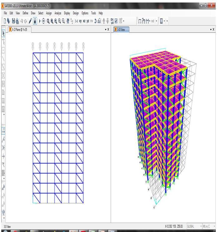
1. Diagonal Bracing: Diagonal bracing consists of inclined structural members that form diagonal
patternswithinthebuildingframe.Thesebracesare typically installed in the form of X-shaped or Vshapedconfigurations.Diagonalbracingeffectively transfers lateral forces between different parts of the structure, providing stiffness and reducing deformationsduringseismicevents.Itoffersgood overallstabilityandisoftenusedinsteelandtimber structures.
2. Chevron Bracing: Chevron bracing is a type of diagonalbracingthatinvolvesaseriesofV-shaped braces arranged in parallel. The braces are connectedattheirvertices,formingazigzagpattern acrosstheframe.Chevronbracingprovidesefficient load transfer and stiffness while offering architecturalflexibility.Itiscommonlyusedinsteel structuresandcanbeaestheticallypleasing,asthe patterncanbevisibleonthebuilding'sexterior.
3. Buckling-Restrained Bracing (BRB): Bucklingrestrained bracing is a specialized type of bracing that utilizes steel members encased in a ductile material,suchasconcreteorsteeltubesfilledwith concrete.Thisbracingsystemisdesignedtoprevent buckling and maintain its load-carrying capacity duringseismicevents.BRBsofferexcellentenergy dissipationcapabilities,allowingthemtoabsorband dissipate seismic forces effectively. They are commonly used in both steel and reinforced concretestructures.
1.1.1 ADVANTAGES OF STEEL BRACING
1. Steel bracing significantly enhances the lateral strength and stiffness of a structure, making it moreresistanttoseismicforces.
2. Thesebracingsareeconomictouse.
3. Easytoerectandoccupieslessspace.
4. Does not significantly add to the structural weightofthebuilding.
5. Lateral resistance of buildings can be significantly improved by the addition of a bracingsystem.
1.2 TYPES OF STEEL SECTIONS USED
Therearethreetypesofsteel sectionsusedinthestudy –steelanglesections,Isections,andtubesections-eachhave their own distinct characteristics and applications. Understanding their properties and structural behavior is essential for selecting the appropriate section for a given bracingsystem.
2. OBJECTIVES
1. To assess RC-framed buildings with and without steel bracing and determine the maximum displacement,baseshear,inter-storeydrift,andtime periodusingSAP2000softwareinaccordancewith IS:1893-2016.

2. Toevaluatetheimpactofvariousbracingtypeson thestructureandchoosethebracingthatminimises lateraldisplacementandinter-storeydrift.
3. Tocomparetheimpactofvarioussteelsectionson the structural response to earthquakes and select themosteffectivesteelsectiontobeemployedinthe bracingsystem.
3. MODLLING AND ANALYSIS
Table -1: BuildingData

Table-2
Table -3: MemberProperties
SlabThickness 150mm
SizeofBeam 400mmx400mm
SizeofColumn 600mmx600mm(1st and groundfloor) 500mmx500mm(remaining stories)
SteelSectionproperties
SteelangleSection ISA200X200X25
SteelBeam(I)Section ISMB300
SteelTubeSection ISB172X92X5.4
Table -4: SeismicParameters
SeismicZone V
SeismicZoneFactor,Z(Table3 ofIS1893:2016)
ImportanceFactor,I(Table8 ofIS1893:2016)
ResponseReductionFactor,R (Table9ofIS1893:2016) 5
SoilType(Table4ofIS 1893:2016) II
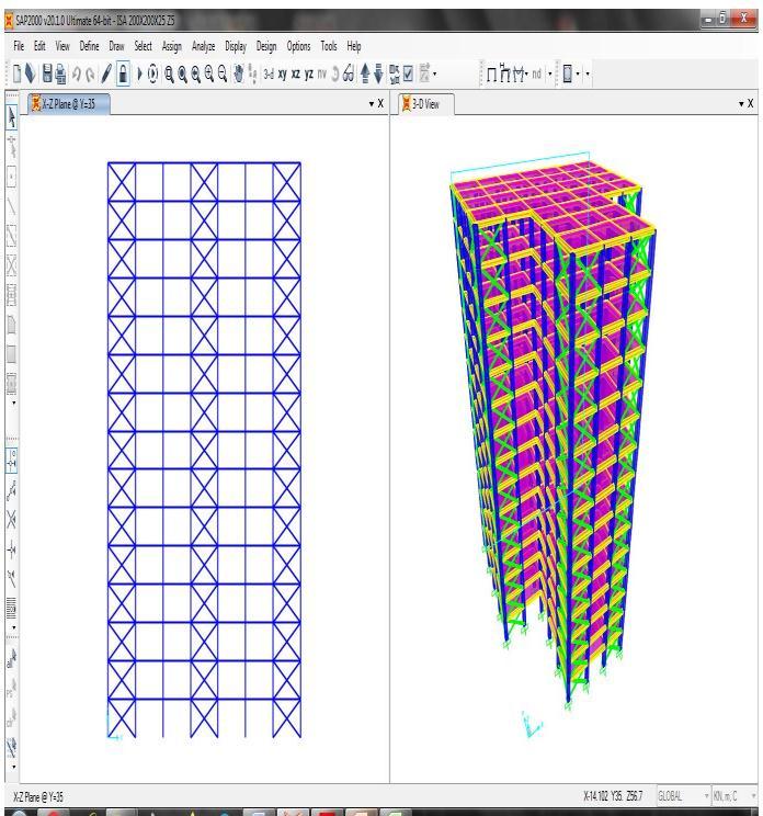
3.1 MODEL OF BUILDING WITHOUT BRACING
3.2 MODEL OF BUILDING WITH BRACING
4. RESULTS AND DISCUSSION

4.1 Maximum Displacement
Thevalueofthestorey'sgreatestlateraldisplacementcaused byalateralloadisknownasthestoreydisplacement.Using timehistoryanalysis,thebuilding'smaximumdisplacement intheXdirectionisdetermined.


4.1.1 X-Bracing
Table-5:MaximumdisplacementusingX-bracingwith differentsteelsections
4.1.2 Diagonal Bracing
Table-6:Maximumdisplacementusingdiagonalbracing withdifferentsteelsections
Table-7:percentagereductionintopstoreydisplacement
Model Steelangle section SteelTube section SteelI section
IthasbeenfoundthatbracingsmadeoftheXtypeofsteel anglesectionreducedisplacement.
When compared to a system without braces, the top floor displacement for the system with X bracing is reduced by 23.67% with steel angle sections, 9.28% with steel tube sections,and7.59%withsteelIsections.
4.2 Storey Drift
Amulti-storybuilding'sstorydriftisthemovementofone level in relation to the level below. It is the difference betweenanyparticularstory'stwofloordisplacementsasthe buildingswaysduetoanearthquake.
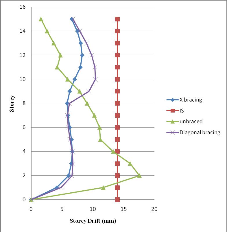
Asgiveninclauseno.7.11.1.1ofIS1893:2016,Storeydriftin anystoreyshallnotexceed0.004timesthestoreyheight.
i.e.0.004x3.5x1000=14mm

So,inourcasestoreydriftshouldnotexceed14mm
4.2.1
X-Bracing
Table-8:StoreyDriftusingX-bracingwithdifferentsteel section
Graph-1:MaximumLateralDisplacements(mm)for differenttypesofbracingswithsteelanglesection
4.1.2 Diagonal
Maximuminterstoreydriftisdecreasedanddistributedmore evenlyalongtheheightofthebuildingwiththeinclusionof steelbracings.
Storeydriftvaluesinunbracedbuildingsareclearlybeyond thelimitspecifiedinIS1893:2016.

Utilisingsteelanglesection,themaximumstoreydriftinthe x-direction is reduced by 65.42% as compared to an unbracedbuilding.
Byminimisinglateraldisplacements,theXtypeofbracings preventscollapsebyloweringstorydriftsinthebuilding.

4.3 BASE SHEAR
Table-11:BaseshearusingXanddiagonalbracingwith differentsteelsections
4.4.1
Incontrasttobuildingswithdiagonal bracingandwithout bracing,itisclearthatthebaseshearofX-bracedbuildings withsteelanglesectionsincreasedthehighest,indicatingan increaseinthestiffnessofthebuilding.
TheX-bracingwithsteelanglesectionbuildingexhibitsthe greatestriseinbaseshear.Thisisduetoanincreaseinthe horizontalseismiccoefficient(Ah)withincreasingspectral acceleration.
Becausethebaseshearandseismiccoefficientaredirectly correlated,baseshearrisesashorizontalseismiccoefficient (Ah)rises.
Graph-4:Comparisonofsteelsectionsintermsof displacement
4.4.2 IN TERMS OF STOREY DRIFT

Types
Graph-3:BaseshearusingXanddiagonalbracingwith differentsteelsections
Graph-5:Comparisonofsteelsectionsintermsof storeydrift

5. CONCLUSIONS
Xtypeofbracingisfoundtobemoreeffectivethan diagonalbracings.
ThereductioninthedisplacementalongXdirection isabout23.67%byuseofsteelanglesection.
Comparativetounbracedbuilding,thereis65.42% reduction in maximum storey drift in x-direction usingX-Bracingwithsteelanglesection.
The base shear of X-braced buildings with steel angle section increased most as compared to buildingwithdiagonalbracingandwithoutbracing which indicates that the stiffness of building increases.
The performance of steel angle section braced frameisbetterthansteelIsectionframeandsteel tubesectionframe.
REFERENCES
[1] Seismic analysis of steel braced reinforced concrete frames. ViswanathK.G,PrakashK.B.andDesaiA.2010, InternationalJournalofCivilandStructuralEngineering, pp.114-122
[2] Behavior of RC framed building with different Lateral bracing systems. Prof.SaritaSingla,MeghaKalra,Rahul Kalra and Taranjeet Kaur. 2012, Proc. of Int. Conf. on AdvancesinCivilEngineering.
[3] Analysis of RC building frame for seismic forces using different types of bracing systems. RishiMishra,DrAbhay Sharma,andDrVivelgarg 2014,InternationalJournalof engineeringresearch&technology(IJERT).
[4] seismic behavior of different bracing systems in high rise RCC buildings. Bharat patel, rohan mali, prataprao jadhavandG.Mohan.2017,InternationalJournalofCivil EngineeringandTechnology(IJCIET)

[5] IS: 1893 (Part 1): 2016: Indian Standard Criteria for Earthquake Resistant Design of Structures, Bureau of IndianStandards,NewDelhi(2007).
BIOGRAPHIES
MIR TABISH ALTAF, M.Tech (EarthquakeEngineering)Dept.of Civil Engineering, Jamia Millia Islamia,NewDelhi.

