Analysing the role of Cable Anchor in Hydroelectric project A case study
Abhishek Siwach¹, Monu Rajpoot²¹ M.Tech Transportation Engineering, IIMT University Meerut (U.P.)
² Assistant Professor, Civil Department, IIMT University Meerut (U.P.)***

Abstract: Purpose of this Scope Cable anchors are tensioned reinforcing elements of higher capacity, consisting of high strength steel tanden fitted with stressing anchorage (fixed length) at inner end, a means permitting force to betransferred,andaheadontherock/Hillsurfaceattheexternalend.Thecableanchorsareusedforstabilizationofsteep slopesorslopesconsistingofsoftersoilsaswellastheenhancementofembankmentsortopreventexcessiveerosionand landslidesprotectionagainstslopestabilityfailures.
The cable anchor is an advanced reinforcement device used in the integration of passive systems to withstand higher loads. Anchors transfer the tensile stress to the soil to absorb stresses due to effective stress loss. In geotechnical engineering, this is called "pre-tensioned post-tensioned grouted soil anchors". Ground anchors can be made from high qualitysteel rodsusing wireorcable anchors.Thetotal length of the rod/wire stripisdividedinto freelength andfixed length. The forces are transmitted to the ground through the bond length/fixed length. The depth of the anchor can be varied to achieve end retention and the desired coefficient of friction to withstand the tensile stress. High performance drilling rigs are used for accurate and stable drilling in dry and wet conditions. Anchors are classified based on the injection technique, the injection method is crucial because it determines the strength of the anchor in the soil and its performance.Itisdeterminedbygeotechnicalengineeringsurvey
This project involves slope stabilization using a anchor system , Before anchoring work at location , significant soil conditionsin the areamustbeestablished.The constructionand designworkof anchoringandgrouting isexplainedas clearlyaspossibleinthisproject,aswellasthedifficultiesassociatedwiththeirwork..
Keywords: Cable anchor, landslides, tensioned, drilling rigs , Technical specification , Chainage , geotechnical engineering.
I-Introduction.
The stability of slopes and rock surfaces is usually lost due to natural phenomena such as water intrusion, freezing and thawing or erosion. However, in certain cases the stability of slopes is affected by changes in land slopes or loading conditions caused by human activities. Therefore, the slopes have an imbalance due to natural causes and human activities.Mainly,slopeimbalancesarerelatedtoroadconstruction,largebuildingsorextensionsofexistingsystems.The largestructurelocatedintheHimalayanlandscapeinvolvestheconstructionofhydropowerprojectstoutilizetheexisting potentialtomeetthehighelectricityneedsofthecountry.Projectsforsiteswithdifficultgeologyareunderwayorwillbe builtinthenearfuture,asmostoftheeasiersiteshavebeenbuilt.Hencestabilization.buildingslopestobuildnewhydro projectsintheHimalayasisachallengeforengineers.
ThehillyterraininHimalayanRegionfallsinthecategoryofyoungestmountainsandneedsprotectionmeasures, mostof the time, whenever some construction is performed for the desired cut in the slopes. These young mountains having fragilegeologyarestillonthevergeoftheirformationandarenotstableascomparedwithsouthernmountainsofIndia. The construction activities in hilly terrain mostly require cutting or filling in the slopes for the construction of building, roadoranyothercivilstructure.Afteranycuttingorfilling,slopesshallbeexaminedforstabilityandprotectionmeasures, if necessary, are implemented. The excavated slopes are frequently of considerable extent and in certain circumstances canevenaffectthestabilityofadjacentzonesandparticularlyslopesandrockfacessituatedabovethem.
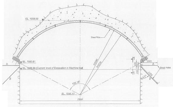
Typical section drawing

Methodology

Thepowerhouseexcavationstagesconstitutecentralpilotandsideslashingfor 8.5mheightfollowedbybenchingworks. During the excavation of powerhouse cavern i.e. Pilot and side slashing works the poor rock conditions is encountered. The cable anchors are proposed to be installed on both sides in poor rock condition encountered stretch. Cable anchors willbeinstalledafterconsolidationgroutingworkscompletionofexcavationofnicheandcastingofcableanchorpad.The excavationwillbecompletedforbenching
Theexcavationlevelfacilitatespositioningofdrillmachine/jackingassemblyforinstallingcableanchors.Furtherinorder to avoid blasting effect, the bench blast is assumed to be taken up ( No mucking till completion of cable anchors works). The excavation of recess/niche shall be completed to start the cable anchor concrete pad works. The excavation shall be done by hydraulic excavator with breaker attachment or manually by rock breakers / Jack hammers. The excavation of nicheisdescribedforunderstandingtheconstructionsequence.
The specialized agency shall be engaged for carrying out cable anchor design and installation works including stressing andtestinginallrespect.Afterthesuitability/liftofftest,thecableanchors320upwardangleat2mc/cspacing19mlong willbeinstalled Thecableanchorsfixingwhichis1.16mbelowpresentconcretebeam/ribbottomsupport levelofstage 1a,b.Theconstructionstagestobeadoptedforcableanchorsinstallationworksaredetailedasunder.Theinstallationand testprocedurefromspecializedagencytobereferredduringconstructionstage.
Cableanchordrawing
Anchoring works shall be taken up as under:
a) Preparation of niche
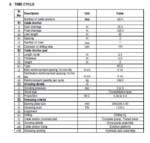
i. The cable anchor works constitutes RCC cable anchor pad 2m height, 0.5m thick with its bottom. The concrete pad is continuous
ii.Theexcavationof500mmniche/recess2mheightinsiderockprofileatinverticalsideshallbecarriedoutpercycle.
iii. The rock support measures like shotcrete, rock bolt & wire mesh shall be completed progressively during the excavation. The excavation shall be taken up by mechanical earns i.e. Chiselling / by hydraulic excavator with breaker attachment/ormanuallybyrockbreakers/Jackhammers.

iv.Theverticalsideniche/recessof2mlengthshallbetakenuppercycle.The rocksupportmeasureslikeshotcrete,rock bolt&wiremeshshallbecompletedprogressively.

b) Preparation of concrete pads
i.Nicheofsize2mlinerlengthx0.5mdeepx2mheightshallbecompleted/cycle.
ii.AlthoughtheRCCconcretepadiscontinuousfromtheconstructionjointisplannedat20-21mlength/pourtofacilitate thecastingsequence.
iii. Reinforcement binding & shuttering works shall be completed at niche locations. Proper care to be taken to be while fixingofinner/rocksidereinforcement.
iv. The pipe 200mm internal diameter at proper inclination and spacing shall be fixed & keep intact for cable anchor drillingworks.
v.CastingforpadwillbecarriedoutbyuseofM35A20gradeconcrete.Thecableanchorconcretepadcastingandstartof cableanchorfixingactivitiesshallbeplannedkeepingsuitabletimeperiodfloat.Refermethodologysketchesattached.
c) Suitability test /Designing of preliminary anchor
i. Suitability test / Lift off test for preliminary anchor shall be designed based on the joint discussions. The various parametersshallbefinalizedbasedontheresult.

d) Drilling of holes for cable anchors
i.Thedrilling will be carriedout bydrilling rig for150mmdiameter hole &19m length.Compressorof suitablecapacity willbeusedalongwithdrillrigtoprovidenecessaryairpressure.
ii. Drilling shall be done by hydraulic rotary or suitable drilling method. The specialized drill bits shall be used. The hole shallbedrilledbyrotarymethodwithwaterflushmethodwithair.
iii.HolesshallbedrilledwithupwardinclinationasshowninGFC.
iv.Beforestartingdrilling,alignmentofdrillrigfeedwillbeproperlysetforcarryingoutdrillinginrequiredangle.
v.Basedonstrata,theremaybepossibilityofcollapseofholes.Insuchcases, partialdrillingofholes,groutingthehole,redrillingtheholeshallbenecessary.
vi.Ifrequired,waterpressuretestshallbecarriedout.Ifwaterlossismorethan3 lugeonconsolidationgroutingshallbe carriedoutasperGFCdrawing
vii.Itisassumedduringthefinalizationofmethodologythatthegroutingworksas perGFCdrawingshallbecompletedin advancepriortocableanchorworks.
e) Fabrication and assembling of anchors
Theanchorsshallbefabricatedoveranelevatedplatform.Strandshallnotbelaidordraggedonsoilorroughsurface.
ii.Thestrandshall becutbyabrasivecutter.Stressinglengthshall beconsidered whilecuttingthestrands.Cutstrandof therequiredlengthasperanchortype
iii.Beforeapplyingfirstcoatofepoxy,strandsshallbecleanedthoroughlytoremoveoil,dustetc.ifanyexist.
Theepoxyformulationinrequiredmixproportionshallbeappliedtotheentirelengthofstrandbeforeitssettingtime.
v.Uponapplicationofepoxycoatingthestrandshallbeallowedfordrying.
vi.Secondlayershallbeappliedoverfirstlayerandmediumquartzorsilica sand(asapplicable)shallbesprinkledonthe strandbeforesettingofepoxy.
vii. Anchor is then assembled properly by using spacers and internal grouting pipe plastic pipe is kept inside bundle of strandfromtoptobottomofanchortoenablepropergroutinginsideanchor.
viii.Theendcap(shoe)isthenfixedattheendoffixedlength(bottomofanchor).
ix.Thewholeassemblywillbeprotectedinstraightorcoiledformaspersiteconvenienceuntilinstallationofanchors.
f) Installation of cable anchor assembly
i.Thecableanchorassemblyshallbeliftedbysuitableliftingdevice/machineryforplacinginthehole.
ii.The cableanchorassemblywill be takentotherespectivehole &will beplaced slowlyinthehole. Thecareshouldbe takenwhileinsertionsothatcableanchorassemblyincludinggroutingpipegetsfitintothehole.
g) Grouting of anchors
i.Thegroutinginsidethecableanchorshallbecarriedoutfromassemblyarea.
ii.Maigroutpumpshallbeusedforcarryingoutgrouting.
iii.Groutpressureandwatertocementratioshallbemaintainedasper specificationorasmentionedinGFCdrawingsor recommendationofagency.

iv.Therequiredtestslikeflowability,shrinkage,bleedingandcompressivestrength
v.Admixturewillbeusedforformingbetterqualityofgroutmix.
vi.Outletofgroutpumpshallbeconnectedtotheinternalgroutingtube/singlewallcorrugatedpipe.
vii.Firststagegroutingoperationshallbecontinuedtillgroutstartoozingoutfromtheanchorassembly.
viii.Aftercompletionofgroutingatoneanchorassemblyareatheconnectionsshallberemovedandfixedatnextassembly anchor grouting tube location. The 2nd stage grouting shall be completed to fill the annular space between single wall corrugatedpipeanddrilledhole.

ix.Tocheckthegroutstrength,requirednumberofcubesshallbecastforeachdayofgroutingoperation.
Consolidationgrouting
h) Mounting of jack
i. Jack of suitable capacity as per design requirement shown in GFC drawing will be used for tensioning of the anchor assembly.
ii.Thejackinglengthofstrandswillbeconsideredrequiredforsuitablejackasperanchoragesystem.
iii. Extra length of anchor shall be considered for jacking purpose above the face of the anchor head as per GFC drawings/requirementtoplacejack.
iv.Strandsatanchorheadareacleanedtoremovedustandoilifany.
v.Bearingplatesareinstalledoverstrandandthenpushedsothatittouchesthethrustplate.
vi.Pushsegmentgrips(permanentwedges)asperrequirementoneachstrandshallbefixedintheslotsofbearingplate.
vii.Thejackwillbemountedoverstrandandrearanchorblockshallbefixedtotheguidetubes.
viii.Thewaxtobeaappliedtomastergripsandshallbefixedtorearanchorblock.Theconicalholeintherearanchorage blockshallbecoatedwithwax.
ix.Basedonrequirementnecessaryplatformforthepersonnelandequipment/toolsshallbeerectedforeasyaccesstothe stressingpoint.
i) Stressing of anchors & acceptance test
i.StressingoperationshallbecarriedoutafterachievingrequiredgroutasstrengthmentionedinGFCdrawing/Technical specification.Thecylinderstrengthvalueof30N/mm2or7daysperiod.
ii.Beforestartingtheactivity,itisensuredthathydraulichosesarewellconnectedtothepumpandjack.
iii. Apply pressure to the jack up to designated first pressure interval,mark the reference point on the cable from a fixed reference(rearbodyofjack).Also,itisrecommendedtomark2-3strandsforreferenceatthesamedistance.Increasethe pressuretothenextdesignatedpressureintervalandmeasuretheelongation.
iv.Theloadappliedontheanchorwillbemeasuredwithpressuregaugemountedonthestressingpump.
v.Thestressingoperationshallbecontinuedinstagestillthefinalpressureand elongationareachieved.Stressingwillbe done by applying load at intervals and elongation will be recorded for checking as per criteria mentioned in the GFC drawings.
vi.Finally,thecablewillbelocked,andjackshallbereleasedtofirstpressure intervalandslipwillbemeasured.Further, the jack will be released to 0 kg/cm2 for demounting. The third stage grouting will be completed based on requirement/procedure.
vii.TheacceptancetestshallbeconductedasperGFC/TSconditionatspecified intervals.Thebehaviorofcableanchorat test load and the deformation shall be observed for period of time in accordance with procedure established during suitabilitytest.
TESTS CONDUCTED ON GROUT MIX:

Flow ability check: This is done using a Flow Cone Apparatus. The time taken for the flow of pre-measured quantity of groutisnotedwhichshallbeintherangeof5to30seconds.
Shrinkage and Bleeding test : Groutmixispouredintoatransparentbeaker. Shrinkageandbleedingaremeasuredand recordsmaintained.
Compressive Strength: Grout cubes of size 100 mm x 100 mm x 100 mm are taken for different W/C ratios and the compressive strength is tested after 7 days & after 28 days. The test results of the grout shall have the following specifications.
CompressiveStrength=notlessthan27MPaat7days.
Expansion=2-3%
Bleedingat3hours=Max,2%,After24hrs–0%.
Sixnos.of100mmx100mmx100mmcubesshallbetakeneachworkingdayforcompressivestrengthtests.
Suitability Test:

1testanchorupto1.10Timesofworkingloadorasspecifiedyour engineeringteamandfollowedbyLIFTofftestatlock offloadwillbecarriedoutatthebeginningoftheproject.
METHOD OF FILLING THE EMPTY SPACE BELOW THE BEARING PLATE
Afterconcretehasset.ThenStartinjectinggroutfromoneofthegrouttube. Whenregulargroutoutflowappears attheothervents,closeventsconsecutivelyinthedirectionofflow.
Groutmust flow the outlet until entrappedairhas beenremoved. When regulargroutoutflowappearsatoutlet, lock thegroutventandmaintainthe workingpressure3-5Barforapproximately30~60seconds,thepressure shouldbeconstantbeforestoppingtheoperation.
Pressureshouldbedulycontrolledsoasnottocausesegregationofgrout,oranyleakageinternally.
Stressing of Tendons
Stressingoperationswillnotcommenceuntilthegrouthasattainedtherequiredcrushingstrengthof30MPaor7 daysaftergroutingwhicheverislater.
PlaceanchorheadPlatetoBearingPlate.
Placetheanchorheadcentrallyabovethebearingplateopeningthestrandsgoingthroughthefollow.
Place the hollow hydraulic jack, connected to a pump with pressure gauge indicator, centrally above the anchor head.
Centralizethebackanchorblockabovethejackwithbackblockwedgesinplace.
Carryoutthestressingofthetendon.
Theelongationsarenotedinastressingformat.
Afterapplyingthedesignedforceandrecordingtheelongationproperly,thestrandsarelocked.
As per BS 8081-1989, All Anchors to be stressed for Acceptance test ( 1 cycle) test and locked at 80% of characteristic strength or 95% of the characteristic 0.1% proof strength stressed and locked with wedges and recorded.
7.3.5 Time cycle activities:
Excavationworks
a)Surveyingandprofilemarking
b)Preparationofnichesurfaceforcastingofcableanchorconcretepad
c)Excavationofnicheportion
d)Rocksupportsystem
Cable anchor concrete pad casting works
a)Preparationofsurface
b)Reinforcementworks
c)Shutteringworks
d)Inspection&checkingworks
e)Cableanchorpadconcreting
Cable anchoring works
a)Liftoff/suitabilitytest
b)Drillingofholeforcableanchorfixing
c)Assemblyofcableanchoraterectionlocation
d)Insertionofcableanchors
e)Groutingthroughpipes/SWC
f)Jacking/stressingworks
g)Grouting&testingworks

SAFETY MEASURES:
(Personal Protective Equipment (PPE)
AllpersonsengagedinthedumpingareashallbeprovidedwithandweartheappropriatePersonalProtectiveEquipment. Atalltimes
SafetyHelmet
SafetyFootwear
SafetyGloves
Eyeprotectorwhengrindingandgrouting
Earprotectorwhendrilling
a) Safety Precautions during Drilling
Ensurethatinsertion&extractionoftemporarycasingpipeareproperlysupervisedbythesupervisor.
Whiledrillingalldrillersarerequiredtowearsafetyhelmets,safetyshoes,safetygoggles&earprotectors.
Ensureproperconnectionofjoints
b) Safety Precautions during Grouting
Since any mistake in the operations of grouting can endanger life and limb of persons, only trained and experiencedpersonnelshallbeentrustedwithcarryingouttheseoperations.
Allgrouthosesandcouplingswillhavesufficienthigh-pressurecapacitytoensurepropergroutingactivity.
Personnelshallwearsafetyshoes,helmet,andglovesduringgroutingoperations.
Duringgroutingoperations,protectiveeyegogglesshouldbeworn.ChecktheSnapcouplingproperly.
All personnel engaged in operations where the danger of grout spray is present e.g. Mixing Grout should wear protectiveeyeglasses.
Ifthegroutentersintotheeyes,itshouldbewashedoutwithcleanwaterandthepatienttobetakenimmediately toaneyeDoctor.AFirstaidkitcontainingcleanwaterwithspraysyringeiskeptatsite.
Groutinghoseconnectionsshouldbecheckedbeforegroutingforanysignsofdamage.
c) Safety Precautions During Stressing
EnsureallJacks&Hydraulicconnectionsareleakproof.
Ensureallpressuregauges&jacksarecalibratedproperlyatregularintervals
andrecordavailableonsite.
Nopersonshallplacehimselfinthelineofjackswhilestressing.
Properinstructionofstressingwithacautionsigniskeptatthelocationofstressingandde-stressing.


Grouting Material and Admixture
ThecementtobeusedforgroutingisOPCobtainedformapprovedmanufacturer/supplier.

Theadmixtureifrequiredwillbeused.ItisfreeofAlumina andisaplasticiserandaretardingagenthavingthefollowing properties
Flowabilityatagivenwater/cementratio.
Reductionofbleedingwater.
Preventionofsegregationingrouting.
Retardinginthesettingofgrout.
Expansionofgrout.
Summary and final statement
Currentresearchonprestressedanchorcablesismainlyfocusedonthenumerical analysisoftheinteractionmechanism betweentheanchorcablesandtherockandsoilmasses,aswellasthemechanicaldeformationoftheanchorcables.There islittleresearchonanchorcablepre-tensionloss.Thiseffecthasasignificantimpactonthequality,safetyandintegrityof a construction or engineering project. The available methods for determining pre-tension loss in anchor cables are as follows.Thefirstmethodisbasedontheuseofavailablemonitoringdatatosummarizethebiasvoltagelawandperforma qualitativeanalysisofthelosscharacteristics.Anothercommonmethodisbasedonlaboratoryteststhatperformafulllife cycle study of prestressed anchor cables. However, this method is subject to many ideal assumptions that are used to reduce the area to be studied when applying internal models. The third method is a process analysis based on the numerical simulation method. This method requires some idealized assumptions, and the analysis of bias loss over time has always been a significant obstacle to effective numerical simulation. To overcome the shortcomings of the aforementionedmethods,thisworkusedregressionanalysisofon-sitemonitoringdataandtheresultsofexistingindoor studiestocreateamathematicalmodelofthelossofanchorcablepretensionsovertimebasedoncomprehensivefactors. Thisrepresentsasignificantimprovementinthemodelingofanchorcablepre-tensionlosscomparedtopreviouswork.In addition, this study found that the proposed model has a wide applicability and the basic concept of the model can be extended to other research methods. This statistically based mathematical modeling and optimization approach solves manyofthechallengesofaccuratelypredictinganchorcablepre-tensionloss.
IV-Conclusion.
Apre-tensionedanchoristhebestsolutionforstabilizinglargeslopes.Todestabilizesoilforces,itisnotenough toprotectpartsoftheslopes,itisnotenoughtolaycablesorbuildaretainingwall.
Couplingefficiencyisprimarilyrelatedtotheselecteddrillholesize.Thenumberoffibersandthedensityofthe steelincreasesastheholesizeincreases,increasingthesetendondamages.
Anchor life is directly related to GUTS (Guaranteed Ultimate Tensile Strength) because the working load is determinedbyGUTS.Wheninvestigatingtheslopestabilizationoffiber reinforcedpolymeranchorsandalsothis typeofanchorsaremostsuitableforslopestabilization,nocorrosionprotectionisrequired.
Consideringvariouscriteria,theanchortypeisselectedandshouldbemoreeffectiveinthefuture
References
1. Hanna, T.H. (1982), “Foundations in Tension- Ground anchors”, Trans Tech Publications, MCGraw Hili Book Company,USA.
2. CASESTUDYONCABLEANCHORINGANDGROUTINGbyMr.C.Chinnaraj,M.E.,M.Nareshkumaar.
5. Researchonprediactionmodelofprestressedlossofcableanchorinsoilrockdualstructureslopeby WeipingTian, JiachunLi,HongliangQi,andZhipeiZhang
6. IS:269-1976Recommendedcodesforselectionofcement

7. IS:9457Codeofpracticeforsafetycolorsandsafetysigns
8. IS:4756-1978(reaffirmed2002).Safetycodefortunnellingwork
9. IS:7293Safetycodeforworkingwithexecutionmachinery.
10. IS:383-1970codesforselectionofSand
11. IS:5878(PartII/Sec2)-1971(reaffirmed1990)codeofpracticeforconstructionoftunnels.
12. IS:5878-3(1972)codeofpracticeforconstructionoftunnels.
13. RDSO/2012/GE:G-0017June2012,Design&constructionoftunnels.
