Analysis And Retrofitting of RCC Building in Seismic Zone III
R.S. Chavan1, Mayur Sargar2, Abhishek Gorlewale3 , Sakshi Shinde4, Vaishnavi Rachetti5 , Sangram Lendave61Guide, Professor, Dept. of Civil Engineering, 2,3,4,5,6B-tech Student, Dept. of Civil Engineering, VVP Institute of Engineering and Technology, Solapur, Maharashtra, India. (DBATU University, Lonere, Maharashtra)

Abstract: - Devastating earthquakes have historically occurred on the Indian subcontinent. The Indian plate is moving into Asia at a pace of about 47 mm/year, which is the main cause of the earthquakes' high frequency and intensity. Nearly 58% of the area in India is earthquake-prone, according to geographic statistics. During the course of their design life, structures must endure loads such as gravity, seismic activity, wind, and others. However, a lot of existing structures might deteriorate or require an upgrade for any of the reasons listed below: 1. A structure that is not code compliant 2. Later code and design practise updates 3. Subsequent seismic zone upgrades 4. Regression of age and fitness 5. Altering an existing structure 6. Modification of the building's use in accordance with the needs of the client, etc. The modelling and analysis of the RC frame buildings has been done by using structure analysis tool ETAB and results found is validated by performing linear static analysis, response spectrum analyses as per IS:1893 (part 1): 2002 After a comparison of the structures with and without bracing, it becomes clear that the structures with lateral force resisting systems are more suited and safe The primary goal of this project is to safeguard both new and old structures by creating an earthquake-resistant framework. Retrofitting is the process of upgrading that makes it possible for an older structure to withstand pressure in situations where Seismic Retrofitting is an upgrade to older structures that makes them more resistant to seismic activity.
Key Words: - Response Spectrum Analysis (RSA), Lead Rubber Bearing, Indian Seismic Zone 3, ETABS, Retrofitting of Structures.
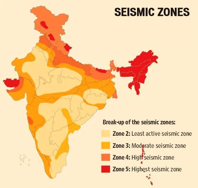
1. Introduction: - Many older structures that were built in conformity with earlier design norms and regulations are frequentlyfoundtobevulnerabletoearthquakedamageduetoinadequatedetailing,incorrectseismicloads,material deteriorationwithtime,andotherissues.Becausenewconstructionisexpensiveandolderstructureshavehistorical value, building owners have opted to renovate them rather than build new ones. In response, governmental bodies passedlegislationrequiringseismicfortification.Thismeansthatmethodstoseismicbuildingrehabilitationmusttake into account both an evaluation of the building's existing lateral-force-resisting characteristics and, if necessary, the installationofnewparts.ZoneIII,azoneofmoderateintensityKerala,Goa,theLakshadweepIslands,portionsofUttar Pradesh and Haryana, the remaining portions of Gujarat and Punjab, West Bengal, portions of western Rajasthan, Madhya Pradesh, the remaining portion of Bihar, portions of northern Jharkhand and Chhattisgarh, and portions of Maharashtra,Odisha,AndhraPradesh,Telangana,Tamil Nadu,andKarnataka.(ReferfigureA)Theprimaryobjective of earthquake resistant design is to prevent building collapse in order to lower the danger of human death or injury during earthquakes. Over the course of a structure's existence, there is incredibly little chance that a catastrophic earthquakewillstrike.Traditionalstructuraldesignspreventstressesandstrainsfromgettingclosetotheelasticlimit for the vast majority of loads. However, in earthquake design, structures are permitted to stretch over their elastic limit in response to ground motion. If a structure had to endure such earthquakes elastically, a pricey lateral load resisting system would be necessary. The structure is anticipated to endure inelastic deformation during a major earthquake;thus,thebuildingmustrelyonitsductilityandcapacitytoreleasehystericenergytopreventcollapse.
2. INTRODUCTION TO RETROFITTING OF BUILDINGS: -

2.1 Moment Frame Seismic Resisting Systems:
SteelMoment-ResistingFrames
ReinforcedConcreteMoment-ResistingFrames
2.2 Base Isolation Systems:
HighDampingBearings
LeadRubberBearings
FlatSliderBearings
Ball&RollerBearings
ElastomericBearings
CurvedSliderBearingsorPendulumBearings
2.3 Diaphragms:
ReinforcedConcreteDiaphragms
WoodDiaphragms
2.4 Shear Wall Seismic Resisting Systems:
ReinforcedMasonryShearWalls
SteelShearWalls
WoodShearWalls
reinforcedConcreteShearWalls
2.5 Braced-Frame Seismic Resistance Systems:
EccentricallyBracedFrames
Buckling-RestrainedBracedFrames(BRBFs)
WoodBracedFrames
ConcentricSteelBracedFrames
2.6 Seismic Isolation and Energy Dissipation Systems
3. MORE ABOUT BASE ISOLATION SYSTEM: -
Abaseisolationsystemseparatesthestructurefromthebase(foundationorsubstructure)asameansofearthquake protection.Theamountofenergythatistransferredtothesuperstructureduringanearthquakeisgreatlyreducedby separatingthebuildingfromitsbase.
Tosupporttheweightofthestructure,thesebaseisolationsystemsfrequentlyfeatureoneormoretypesofbearings. Thesepartsincludethingslikeelastomericpads,slidingplates,andinvertedpendulums.Allofthesepartscandissipate energytosomeextent,althoughusuallyonlybyhystereticdamping.Hystereticdampingcanoccasionallytriggerhigher modesbuthassomerestrictionsonhowmuchenergyitcanabsorb.
3.1 There are Six major types of base isolation devices: -
ElastomericBearings
HighDampingBearings
LeadRubberBearings
FlatSliderBearings
CurvedSliderBearingsorPendulumBearings
Ball&RollerBearings
3.2 Advantages:
1.Lesssevereearthquakedisplacements.
2.Reducedthestructuralcostbyloweringtheseismicdemandonthestructure.
3.Lessenedtheharmcausedbyearthquakes.Thisaidsinkeepingthestructureoperatingwellafteranevent.
4.Increasesthesecurityofstructures
5.Propertypreservation
6.Improvesastructure'sperformanceunderseismicloads.

4. INTRODUCTION: LEAD RUBBER BEARING:
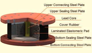
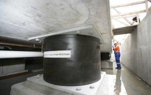
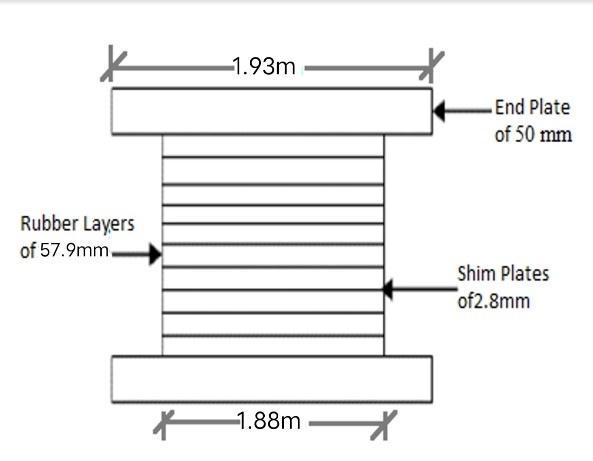
In the event of an earthquake, LRB lead rubber bearings' base isolation principle restricts the amount of energy that is transferred from the ground to the structure. The Base Isolation A laminated rubber and steel bearing with steel flange platesforinstallationtothestructuremakesupLeadRubberBearings(LRB).Everyisolatorhasaleadcorethatdissipates energy.Theisolator'srubberservesasaspring.Althoughquiterigidvertically,itisverysoftlaterally.Thinrubberlayers strengthenedbysteelshimsareusedtocreatethehighverticalstiffness.
Howdoesalead-rubberbearfunction?Theun-isolatedbuildingwillvibratebackandforthindifferentdirectionsduring theearthquakeasaresultofinertialforces,whichwillcausethebuildingtodeformandsustaindamage.Theleadrubber bearing effectively dissipates the inertial force upon the building, lengthens the period of vibration, and reduces the acceleration of the building. In contrast, the base isolated building will also move but maintain its original shapes and avoiddamages.Duringanearthquake,theleadplugwillslidealongthelaminatedrubber,butitwilltransformthisenergy ofmovementintoheatinstead,whichwilleffectivelylessentheinertialforceactingonthebuildingandreducevibration. Duetoitsgreatelasticity,therubbercomponentwillcontinuetomaintainitsoriginalshape.
5. OBJECTIVES: -
a. toenhancethedisplacementofthebaseisolatedstructurerelativetotheconventionalstructureinallstories, includingthebottomstories.iftimehistoryanalysisisused.
b. To develop the Lead rubber bearing utilising E-TABS data and to investigate the effectiveness of providing Leadrubberbearing(LRB)inthebuilding.

c. Using the comparable static analysis, response spectrum analysis, and time history analysis methods, determinethestoreydisplacements,storeydrift,andstoreyshearateachstorey.
d. When compared to a normal building with the same conditions, the G+7 storey RC bare frame is separated utilisingLeadrubberbearing(LRB)topreventstoreydrifts,whichwillaidinthedevelopmentofearthquakeresistantstructures.
6. METHODOLOGY: -
a. ETABSv21.0.0istheprogrammeusedforstructureanalysis.
b. Forstructuralanalysis,dynamicanalysisisused.
c. IS 1893 (PART I) 2016, UBC 1997, UBC Isolated 1997, IS 875 (PART 1, 2, and 5 for dead load, live load, and combinationload,respectively)arethecodesutilised.
d. Inthisproject,thereareseveralsortsofdynamicanalyses.Time-historyanalysisutilisingTukeyEarthquake2023 earthquake data was primarily done as the IS code suggests Response Spectrum study only over the 30m hight buildings.
e. ForTime-HistoryAnalysisTukeyEarthquake2023earthquakedataisused
f. TheloadsareappliedinaccordancewithIS875(PARTIandII)coderulesafterthebuildinghasbeenmodelled. Reaffirmedforbothliveanddeadloadsin2008
g. Themaximumaxialloadisindicatedfromsupportresponseresultsforbothinternalandexternalsupportsafter theanalysisofafixedbaseconstructioniscompleted.
h. Followingtheidentificationoftheaxialload,theLeadcorerubberbearing(LRB)isthencreatedforeachinternal andexteriorcolumnindependentlyinordertosupportthemaximumaxialload.
i. As link properties for the base isolation structure in E-TABS, the properties of the lead core rubber bearing are thendetermined.
j. ThentheBaseIsolationStructureisanalysedforsimilarconditionatdifferentsupport.
7. ANALYSIS (TIME- HISTORY): -

Ananalyticaltechniquecalledtime-historyanalysisisbasedonhistoricalgroundmotiondatafrompreviousearthquakes. In this kind of analysis, the previous earthquake is applied to the structure. The software receives historical earthquake dataandgenerateswavesforaspecificamountoftime.Thegraphbetweenaccelerationandtimeshowshistoricaldatafor theperiodoftime.WiththeaidofTime HistoryAnalysis,differentgraphand tabularfiguresmaybecreated,andwecan also examine the building's response spectrum. A response spectrum is a curve that is drawn between the maximum responseofasingle-degree-of-freedomsystemandthefrequency(ortimeperiod)oftheseismicmotion.
7.1 Details of Building: -
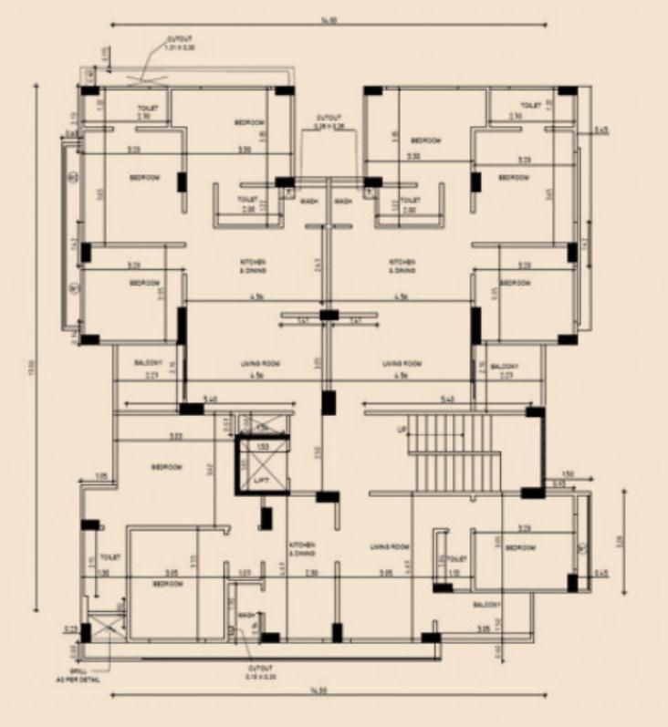
TheanalysiswasperformedusingETABSversion21.0.0
unitswere"KN-m"
codeprovisionswereUBC1997andIS1893(Part1)
Timehistoryanalysisisthetypeofstudyperformedon2016andUBCIsolated1997.
Structure:RCC
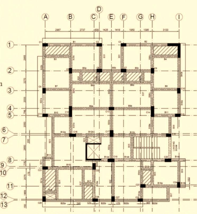
StructureType:PlanIrregularstructure
PlanDimension:25.5m×16m
HeightofBuilding:G+7(24.432m)
HeightofEachStorey:3.05(10.1feet)
BuildingType:residential
International Research Journal of Engineering and Technology (IRJET) e-ISSN:2395-0056

Volume: 10 Issue: 06 | Jun 2023 www.irjet.net
7.2 Materials Details:
GradeofConcrete:M25(ForBeamsandcolumn)
M25(ForSlabandshearwallinliftarea)
GradeofSteel:Fe415
7.3 Section Details:
labThickness:150mm
Wallthickness:230mm
Beamandcolumnsdimensionsshowninfig
7.4 Loads
DL:Column,Beam,Slab(constant)
LLforFloors=3.0kN/m2
LLforRoof=1.5kN/m2
FF=1.0kN/m2
WallLoad:T×density×H=0.23×18×2.9=12.006kN/m
ParapetLoad:=0.23×18×0.9=3.726kN/m
7.5 Lateral Load for Response Spectrum Analysis (according to UBC 1997)
SeismicZoneFactor(Z)–Zone3
SeismicSourceType–B
NearSourceFactorNa–1
NearSourceFactorNv–1
Dampingcoefficient(βDorβM)–1
Damping(βeff)–5%(forConcretestructure)
SoilProfileType–Sc
SeismicCoefficientCa-0.36
SeismicCoefficientCv(CVD)-0.54
ImportanceFactor(I)–1.25
ResponseReductionFactor(R)–8.5(ForSMRF)
7.6 Detailing of Models
Model1:Time-HistoryAnalysiswithLeadRubberBearing(LRB)isolated.
Model2:Time-HistoryAnalysiswithFixedBase
7.7 For Internal and External Columns Design of Base Isolator (LRB)
2395-0072
Leadrubberbearingisolatorsarethekindofbaseisolatorsthatareusedforanalysis,andtheyaredesignedasisshown belowinordertodeterminetheirqualities.Makeanoteofthelargestsupportreaction(W).AfterModel2'sstudy,the greatestsupportreactionisnoted.
Maxsupportreaction Ext.Colm= ,Maxsupportreaction Int.Colm= DesignFormulasforLRBcalculations:-
1 DesignDisplacement, Int.Colm Ext.Colm
2 BearingEffectiveStiffness, ( )


24.Vertical
7.8 Placing of Lead Rubber Bearing
Therearebaseisolatorsatbaselevelandisolatorsaboveeveryfooting.Thetablesbelowlistthecalculated propertiesofLRB.
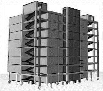

inputvaluesfortheLRBIsolatorforinternalcolumnsinETABSinTABLENo.7.8.1
inputvaluesfortheLRBIsolatorforexternalcolumnsinETABSinTABLENo.7.8.2
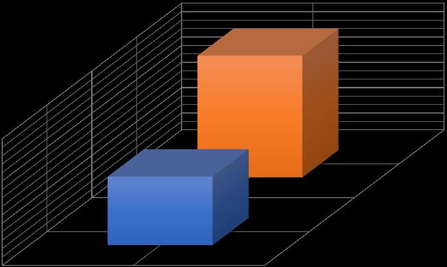
Thebaseshearistheamountofreactiveshearforceneededtofullystabilisethestructureduringseismicaction,whereas story shear is the shear generated at each storey during seismic action. earthquake movement. As can be observed, comparedtoafixedbasebuilding,thestoreyshearinthex-xdirectionwasdramaticallyreducedateachstoreyinthebase separatedbuilding.Thisindicatesthatthebaseisolator'sbaseshear,baseshear,lateralloadateachfloor,etc.arereduced aftertheintroductionofLeadrubberbearing.Whencomparedtoafixedbasebuilding,thestoryshearsinthex-xdirection atthetopstoryofthebaseisolatedbuildingarereducedby89.725%.Overallbasesheardecreasedby41.288%.


Thefollowingfindingscanbedrawnfromtheseconstructionmodelsafterdoingatimehistorystudyonthebaseisolated byprovidingleadrubberbearing.
Aftertheleadrubberbearing(LRB)isgivenasabaseisolationsystem,theinfluenceofearthquakesonthe buildingisdecreased,resultinginareductioninstoreyshearforeachlevel.
AftersupplyingLRB,baseshearisalsodecreased,whichstabilisesthestructureduringearthquakes.

Additionally,eachstorey'sstoreydriftisdecreased,especiallyinhigherlevels,makingthestructureearthquakesafe.
AfterimplementingLRB,pointdisplacementsineverystoryincreased,whichiscrucialformakingabuilding flexibleduringanearthquake.
Whenthereisanearthquake,modeperiodsarelengthened,whichlengthensastructure'sresponsetime.

Basesheardecreasedforbaseisolatedstructuresupto3252.9089KNasopposedto5759.6789KNforfixedbase supportedstructures.
Finally,itcanbesaidthatwhenLRBisusedasabaseisolationsystem,thestructureismoreearthquake-resistant andrequireslessreinforcing,makingitmorecost-effective.
10. REFERENCES: -
[1].Adams, Scott Michael ( 1 ); “Performance- ased Analysis of Steel uildings: Special Concentric raced Frame”, CaliforniaPolytechnicStateUniversity.
[2]. IS13827,1993,IndianStandardGuidelinesforImprovingEarthquakeResistanceofEarthenBuildings.
[3]. IS 13828, 1993, Indian Standard Guidelines for Improving Earthquake Resistance of Low Strength Masonry Buildings.
[4].Seismic Retrofitting of Structures by Steel Bracings (Mander, J.B., Priestly, M.J.N., and Park, R., Observed Stress
strainbehaviourofconfinedconcrete,JournalofStructuralEngineering,Vol.114,No.8,1988.)
[5].Agarwal,Pankaj&Shrikant,Manish( );“Earthquake esistantDesignofStructures”,NewDelhi,PrenticeHall.
[6].Seismic Retrofitting Resilience-Based for Strategic RC Buildings (Mar 2021, DOI: 10.3390/buildings11030111, ISBN:2075-5309)
[7].Reliability-based optimization of multiple nonlinear PTMDs for seismic retrofitting of buildings (DOI: 10.1016/j.istruc.2022.08.121,ISBN:2352-0124)
[8]. IS456:2000,Codeofpracticeforplainandreinforcedconcrete.
[9]. IS875,Codeofpracticefordesignloads(part1deadload,part2liveload&part5Combinationload).
[10]. IS 13920, 1993, Indian Standard Code of Practice for Ductile Detailing of Reinforced Concrete Structures SubjectedtoSeismicForces.
[11]. IS15988:2013seismicevaluationandstrengtheningofexistingreinforcedconcretebuilding-Guidelines.
[12]. IS 4326:2013, Indian Standard Code of Practice for Earthquake Resistant Design and Construction of Buildings (3rdRevision).
[13]. IS1893(PartI),2016,IndianStandardCriteriaforEarthquakeResistantDesignofStructures(6thRevision). [20] UBC97
[14]. Astana, Alhassan ( 1); “Seismic Behaviour and Design of Steel Shear Walls”, Structural Steel Educational Council.
[15]. IS13935,1993,IndianStandardGuidelinesforRepairandSeismicStrengtheningofBuildings–Guidelines.
[16]. Barron, Joel M.& HasteMary ethD.( 4);“DiaphragmEffects in ectangular einforcedConcrete uildings”, ACIStructuralJournal,TitleNo:101-S60.

