Truck Chassis Analysis using Finite Element Method for Steel and Carbon Fiber Components
Gyan Prakash1,2 , Dr.Shahnwaz Alam2 , Kamran Rasheed2Abstract –The foundation of any vehicle, referred to as its frame or chassis, plays a pivotal role in the automotive industry. Much like the skeletal system of a living organism, it serves as a sturdy structure that holds together all major components. Its primary objectiveis toprovidesecuresupport, ensuring the vehicle can bear the maximum load across diverse operating conditions. The chassis must possess ample strength to withstand both heavy loads and sudden shocks. Being the central component ofanautomobile, thechassis acts as a framework to uphold the vehicle body. Therefore, it must exhibit exceptional rigidity and robustness to endure the dynamic forces, vibrations, and stresses encountered during vehicle motion.
Traditionally, steel has been the predominant material usedin chassis manufacturing, gradually giving way to aluminum over time. However, this study delves into the exploration of replacing conventional materials with ultra-lightweight carbon fiber composites. The extraordinary strength and lightweight nature of carbon fibers render them highly suitable for producing automotive chassis. The study specifically focuses on conducting modal and static structural analyses of the Tata LPT 3118 truck chassis frame, comparing the performance of both steel and carbon fiber materials. The analysis encompasses a comprehensive evaluation of stress, strain, and total deformation values for each material. Employing the finite element method, the chassis is modified using SOLIDWORKS 2016, followed by Finite Element Analysis and Modal Analysis performed on a dedicated workbench.

Key Words: FEM,Compositematerial
1. Introduction
Theessenceofanautomobileliesinitstwovitalelements: theBodyandtheChassis.Thechassis,specifically,pertains tothevehicle'sstructureintheabsenceofthebody.Itserves asthebedrock upon whichanassortmentofchassisunits findtheirplace,connectingtotheaxlesthroughspringsand other components that transfer or absorb the axle's force and rotational power. In the formative years of the automotiveindustry,chassisframescameintobeingusinga medley of materials, including tubular steel, rolled steel sections, wood, and fortified wooden sills featuring steel flitchplates.
Thechassisassumestheroleofthefundamentalframework in a commercial vehicle. In the days preceding the 1930s, nearly all motorized vehicles boasted a distinct structural frame, known as the body-on-frame design, which stood apartfromthevehicle'sbodyitself.Insubsequentyears,the majority of passenger cars transitioned to a monobody construction, seamlessly integrating the chassis and bodywork. However, trucks, buses, and pickups have continued to embracea separateframeastheir dedicated chassis.Thischassisframeprovidessupporttoanarrayof vehiclecomponents,encompassingtheengine,transmission system (consisting of the clutch, gearbox, propeller shaft, andrearaxle),wheelsandtires,suspensionsystem,aswell as control mechanisms such as braking, steering, and electrical components.Therefore, itis often referredto as the"carryingunit."Theprincipalfunctionalitiesfulfilledbya frameinmotorvehiclesareasfollows:
Providingsupportforthevehicle'smechanicalcomponents andbody.
Shapingthevehiclebody.
Dealing with static and dynamic load conditions without excessivedeflectionordistortion.Theseloadsinclude:
Weightofthebody,passengers,andcargo.
Verticalandtorsionalforcestransmittedwhiletravelingon unevensurfaces.
Transverselateralforcesresultingfromroadconditions,side winds,andsteering.
Torquefromtheengineandtransmission.
Longitudinal tensile forces during acceleration and compressionduringbrakingandcollisions.
Theautomotivechassis,acrucialelement,bestowsstrength and stability upon a vehicle across diverse conditions. Serving as the sturdy framework that unites the engine, body,axles,powertrain,andsuspensionsystem,itrelieson tiebarsasconnectorsforallautomobilecomponents.Among theoldestchassisdesigns,theladderchassisreignssupreme withitsexceptionalload-carryingcapacity.SUVsandheavy commercialvehiclescommonlyembraceladderchassisdue to their ability to bear substantial loads, delivering
commendable driving dynamics and ride comfort. Consequently,ladderchassisenjoywidespreadpreference overunibodyandbackboneframes.
The ladder chassis frame exhibits longitudinal side bars interconnectedbycrossmembers.Additionalbracketslend supporttothebody,whilethedumbironassumestheroleof a bearing for spring shackles. The fusion of chassis componentsisachievedthroughrivetedjoints,weldjoints, or bolts. Notably, the ladder frame adopts an upsweep at boththefrontandrear,accommodatingthespringingaction of the suspension system. To enhance steering lock, the frame narrows at the front. Frame construction employs diverse cross sections, such as channel, box, hat, double channel,andI-section,offeringversatilityandadaptability
The automobile chassis serves as the foundation of the vehicle, encompassing essential elements such as tires, engine, frame, driveline, and suspension. Within this assemblage, the frame plays a pivotal role in providing crucial support. It mustpossessamplestrength to endure shocks, torsion, vibrations, and other forms of stress. The chassisframeconsistsofinterconnectedsidemembersand crossmembers.Todetectvulnerableareaspronetofatigue failure,stressanalysisutilizingFiniteElementMethod(FEM) can be employed. By assessing the stress magnitude, it becomespossibletopredictthelifespanofthetruckchassis, withtheaccuracyofthispredictionrelyingonstressanalysis outcomes.
Conducting stress analysis on the chassis helps identify critical points exhibiting elevated stress levels [3]. These criticalpointsarevitalcomponentsthatcantriggerfatigue failureinthechassisframe.Consequently,thelongevityof the fire truck chassis is heavily contingent upon the magnitudeofstressitendures.Inthisstudy,bothmodaland static structural analyses are conducted on the ladder chassis. Modal analysis involves determining natural frequencyandmodeshape.
To effectively manage the vibrations generated by the engine,suspension,anddriveline,thechassismustpossess rigidity and strength. Steel and aluminum have long been used as conventional materials for chassis construction. However, carbon fibers offer numerous advantages over these traditional options. Carbon fibers exhibit superior strength and stiffness while remaining lightweight. Furthermore,theycanbeeasilymoldedintovariousshapes. Theutilizationofalightweightchassisreducesthevehicle's fuel consumption, thereby enhancing fuel efficiency. Consequently,manufacturersfavorultra-lightweightcarbon fiberchassistobolsterthestrengthandstabilityofvehicles.
The emergence of computer aided design and computer aided engineering has been primarily driven by advancements in computer technology, making powerful tools more affordable and accessible. These tools offer

predictive capabilities and valuable insights into complex engineering processes. Consequently, engineers across variousdisciplinesnowrequirenumericalsolutiontoolsto investigate problems that were previously only solvable through experiments. In many instances, the modeling of engineering problems leads to ordinary and partial differentialequations,oftenofanonlinearnature.Overthe past50years,thefiniteelementmethodhasemergedasa powerful solution tool for addressing these differential equations. Roslan Abd Rahman and his colleagues (2008) delved into the stress analysis of a robust chassis used in heavy-dutytrucks.Stressanalysisplaysavitalroleinfatigue studies and predicting the lifespan of components by identifyingcritical pointswiththehigheststresslevels. In their analysis, they focused on a specific truck model and utilizedtheABAQUSsoftware,acommercialfiniteelement package.Thedimensionsofthemodelwere12.35metersin length and 2.45 meters in width. The chassis material employedwasASTMLowAlloySteelA710C(Class3)witha yieldstrengthof552MPaandatensilestrengthof620MPa. Theirfindingsrevealedthatthecriticalpointofstresswas located at the chassis opening where it came into contact with the bolt. The stress magnitude at this critical point reached 386.9 MPa. This critical point indicated an initial stageofpotentialfailure,asfatiguefailurestendtoinitiate fromareasexperiencingthehigheststress.
Romulo Rossi Pinto Filho [30] presented a relevant case study that focused on optimizing the design of off-road vehicleframes.Theprimaryobjectiveofthisresearchwasto achieve an optimized chassis design with appropriate dynamic and structural behavior. The study consisted of three main steps. Firstly, a software based on the finite elementmethod(FEM)wasusedtomodelthechassisofa commercialoff-roadvehicle.Secondly,aseriesoftestswere conducted to collect data for modeling and validation purposes.Finally,withthevalidatedmodel,theresearchers performed structural optimization to improve torsion stiffnesswhilemaintainingtheoverallmassofthestructure. Anothernotablecasestudy,ledbyWeslyLintonatCranfield University(34),focusedexclusivelyonachassisprovidedby LuegoSportsCarsLtd.Theinitialassessmentofthechassis revealedatorsionvalueofapproximately1330Nm/degand a mass of 120.1 kg. To bolster the torsion stiffness, the research team implemented a series of adjustments and enhancements.Theseincludedthestrategicincorporationof additional cross bar structures and the utilization of advancedstructuralmaterials.Asaresult,theoveralltorsion stiffness experienced a staggering increase, reaching an impressive 337% of its initial value. These modifications yielded substantial improvements to the overall chassis structure,leadingtoenhancedperformanceintermsofride quality,vibrationreduction,andmore.
Therefore, based on the literature survey, in this study, Modal Analysis and Finite Element analyses were used to studyandunderstandthecharacteristicsofatruckchassis
(truckTATALPT3118).Theanalysisresultswerecombined tocreateavirtualmodelusingFiniteElementMethod(FEM) tools,whichwasthenrefinedthroughacorrelationprocess. Further analyses were conducted to identify the most suitablematerial forthetruck chassisdesign. Tofacilitate thestudy,thetruckchassiswasmodeledusingSolidWorks softwarewhilemaintainingtheoriginaldimensionsofthe structure. The model was then imported into ANSYS Simulation software to determine the natural frequencies andmodeshapes.Foraccuraterepresentationofthesolid chassis,10node-tetrahedralelementswereselectedforthe meshing analysis. The next step involved conducting Experimental Modal Analysis on the actual truck chassis structure to obtain the natural frequencies, mode shapes, and damping ratio. The analyses were performed on the ANSYSsimulationbenchtoensurethequalityoftheresults. The findings from the finite element analysis and experimental modal analyses were then compared to identifythemostsuitablematerialforthetruckchassis.
A correlation analysis was conducted to assess the agreement between the finite element analysis and the modeltesting.Theexperimentaldataservedasareference forthemodelupdatinganalysis.Basedontheoverallresults, appropriatematerialselectionwascarriedouttoenhance the strength of the truck TATA LPT 3118 chassis. The subsequent section provides a detailed description of the stepsrequiredforeachmethodemployedtoestablishavalid representativeFEmodel.

2. Numerical details
Detailedprocedureofnumericalsimulationisdiscussedin thissection.
2.1 Identification of problem


Thefundamentalstructureofthetruckisitschassisframe, whichplaysavitalroleinsecurelycarryingheavyloadsin variousoperationalsituations.Itsmainfunctionistoabsorb thetorquegeneratedbytheengineandaxles,whileenduring theimpactofchallengingroadconditionswhenthevehicleis inmotion.
Forthisspecificproject,thetruck'schassisfallsunderthe category of a ladder frame type. A typical ladder frame chassis for commercial vehicles is illustrated in Figure 7. Structurally,aladderframecanbecomparedtoaseriesof interconnectedgrillages.Thesidemembersoftheframeact asabarrieragainstshearforcesandbendingloads,whilethe crossmembersprovidetorsionalrigidity.Lightcommercial vehiclechassiscommonlyfeaturesturdyboxsectionsteel frames,whichofferbothverticalandlateralstrength,aswell asresistancetotorsionalstress.
Theuseofaladderframechassisoffersbothadvantagesand disadvantages. One notable advantage is the ease of mountinganddismountingthebodystructure.Awiderange
ofbodytypes,suchasflatplatforms,boxvans,tankers,and detachablecontainers,canbeeasilyadaptedtoastandard ladderframechassis.Moreover,thedesignofrubberchassis effectively isolates the noise generated by the drive train componentsfromthepassengercompartment.Thisdesign approach not only proves relatively inexpensive but also simplifies the manufacturing process compared to other chassistypes.
However, ladder frames do come with some drawbacks. Torsionalrigidityisanotableconcernforladderframesdue to their two-dimensional structure. They exhibit lower torsional rigidity compared to other chassis types, particularly when subjected to vertical loads or bumps. Additionally,ladderchassisdesignstendtobeheavierthan alternative chassis designs. Another drawback is the suboptimalconditionofthechassisstructurebeinganalyzed inthiscase.Corrosioninseveralpartsofthechassiscould impactitsstrength, especiallyinthe weldingareas,which may affect the analysis results. The table provides the specificationsofthematerialsusedforanalyzingthetruck chassis.
2.2 Solid Modeling
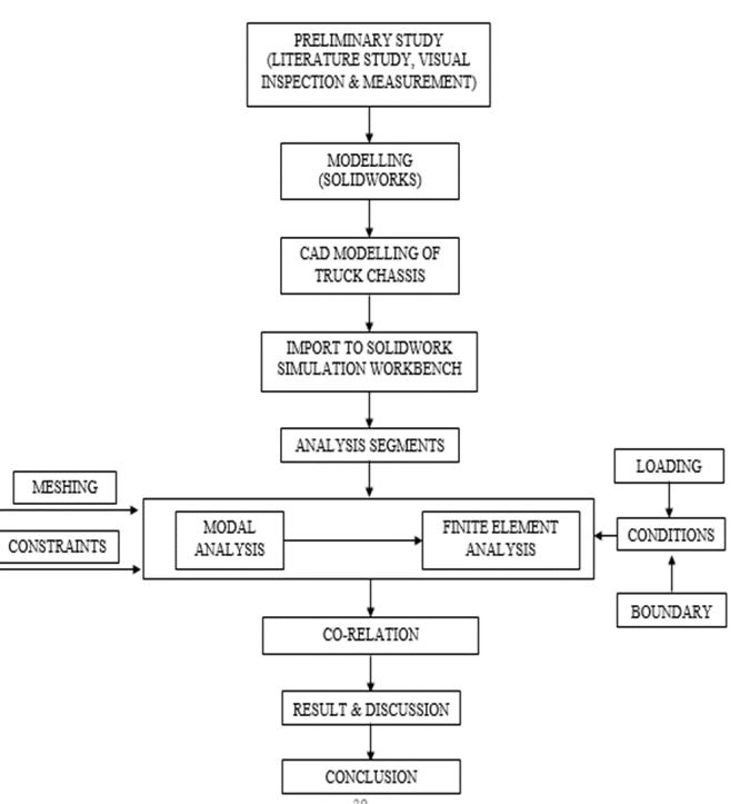
The Fem technique is employed to conduct static structural analysis on the chassis of a truck using ANSYS simulationsoftware.Initially,athree-dimensionalmodelof thetruckchassisiscreatedusingSOLIDWORKS3Dmodeling
software.Subsequently,theframemodelisimportedintothe Solidwork Simulation Workbench to facilitate the analysis process.

thetruckcapacitybecomes98,100N.Additionally,theweight ofthebodyandengineamountsto2tons,equivalentto2000 kgor19,620N.
Consequently,thetotalloadactingonthechassiscomprises thesumof10,000kgand2000kg,or98,100Nand19,620N, respectively, totaling 117,720 N. As the chassis consistsof two beams, each beam bears half theload imposed on the chassis. Therefore, the load on a single beam can be calculatedas117,720Ndividedby2,resultingin58,860N perbeam.

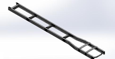

Themodelundergoesmeshing,employingatotalof76,399 nodes and 40,378 Tetrahedral elements. To enhance the accuracyoftheoutcome,amorerefinedmeshingtechniqueis employedspecificallyintheareabelievedtoexperiencethe greateststress
Inthisanalysis,staticforcesareemployedastheloadsonthe chassismodel.Weassumethatthemaximumweightofthe loadedtruckandbodyis10tonnes.Moreover,weconsider theloadtobeuniformlydistributedacrossthechassismodel. Consequently,anetforceof117,720Nisappliedtotheupper sideofthechassisframe.Bothsidebarsequallywithstand thisnetload,witheachsidebarcarryingaloadof58,860N. Theconnectiontypeemployedinthisanalysisinvolvesrivets, whichjointhecrossbars,sidebars,andbrackets
2.5
Theroleoftheloadapplicationisofutmostimportancewhen conductingcomponentanalysis.Oneencountersvariousload types, including the Uniformly Distributed Load (UDL), Uniformly Varying Load, and Point Load. The current frameworkincorporatestheUDLspanningitsentirelength. Thetruckchassismodelexperiencesstaticforcesexertedby thetruckbodyandcargo,therebyapplyingpressure.
Let'sdelveintothespecificsofthetruck'scapacity.Thetruck hasamaximumcapacityof8tons,whichcanbetranslatedto 8000kgor78,480N.Takingintoaccounta1.25%increment,

3. Result and discussion


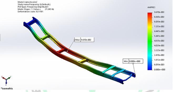
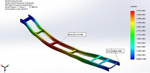
Modeshapesrefertothevaryingshapesofastructureat different natural frequencies. These mode shapes are determined by utilizing the Eigen values derived from vibrationequations.
Modal analysis holds significant importance as a fundamental aspect of dynamic character analysis. This contemporary approach allows for the identification of natural frequencies and mode shapes of structures. By analyzingrigidity,theoccurrenceofresonancevibrationscan be mitigated. Through modal analysis,one can discern the distinctive characteristics exhibited by each mode of the structure,whilealsopredictingtheactualvibrationresponse withinthefrequencyrange.Theinsightsgainedfrommodal analysisserveasvaluablereferencepointsforotherdynamic analyses,suchasrandomanalysisandharmonicanalysis.In thespecificcontextofthisstudy,a3Dfiniteelementanalysis is conducted on the modal analysis of the chassis frame, utilizingtheANSYSSIMULATIONWORKBENCHsoftware.
In the modal analysis of the frame, only fixed support boundary conditions are applied, thereby eliminating the need for other conditions like loading and gravitational acceleration.Consequently,themodalanalysisisperformed on a structural steel frame, yielding the following mode shape.

3. CONCLUSIONS
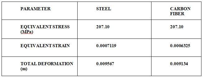
TheladderchassisoftheTata LPT3118 truck underwent modal analysis and static structural analysis. The results revealedthatwhencomparingsteelandcarbonfibers,the vonequivalentstressforcarbonfibersincreasedwhilethe totaldeformationdecreased.Thisindicatesthatthestress values of carbon fibers remain within acceptable limits. Consequently,carbonfiberemergesasanidealmaterialfor vehicle chassis due to its remarkable strength and lightweightnature.Infact,whenconsideringthesameload carryingcapacity,carbonfibersarepreferableoversteelfor constructingladderframes.Thisisbecausethecarbonfiber frameweighssignificantlyless(54.28kg)comparedtothe steel frame(170.45kg),resultingina weightreductionof 60-68%whilesimultaneouslyenhancingthestiffnessofthe chassisframe.However,it'simportanttonotethatcarbon fibermaterialsarerelativelymoreexpensivethansteelfrom aneconomicstandpoint.
REFERENCES
[1] I.M.Ibrahim,D.A.CrollaandD.C.Barton,“EffectOfFrame Flexibility On The Ride Vibration Of Trucks”, Department of Mechanical Engineering, University of LeedsLS29JT,U.K.August1994.
[2] Pomulo Rossi Pinto Filho, “ Automotive Frame Optimization”, Universidade Federal de Uberlandia. November2003.
[3] Wesley Linton, “Analysis of Torsional Stiffness and Design Improvement Study of a Kit Car Prototype”, CranfieldUniversity,Setember2002.

