
Design & Analysis of Bend Removal/Creation & Multipurpose Hydraulic Press Machine.
Rohan
Panage1 ,
Kshitij Asar2 , Shubham Chaudhary 3 , Tushar Sonawane41Professor, Dept of Mechanical Engineering, PVG’sCOET PUNE, Maharashtra, India.

2Student, Dept of Mechanical Engineering, PVG’sCOET PUNE, Maharashtra, India.
3Student, Dept of Mechanical Engineering, PVG’sCOET PUNE, Maharashtra, India.
4Student, Dept of Mechanical Engineering, PVG’sCOET PUNE, Maharashtra, India. ***
Abstract - Ahydraulicpressmachineisamachinethatuses ahydrauliccylindertogenerateacompressiveforceonthe workpiece.Inthistheframe,table,pilers,hydrauliccylinder arethemaincomponentsandallthisaredesignedbydesign procedure and the earlier reference model. And by optimizingthematerial andtheweightofthestructure of thehydraulicpressit will resultin the costreduction. We madeaattempttowardsreducingthevolumeofthematerial usedintheframestructureofthehydraulicframe.Wehave designedthispressforindustrialapplicationsandbyusing H-shaped structure we got to see that a large variety of operationscanbeperformedinasinglepressmachineby justchangingthefixtures.Ourmainpurposebehindmaking thishydraulicpressistoremovethebendsofthedifferent manufacturedpartscreatedduringmanufacturing.Tobend anypart,weneedtoapplyforceabovetheelasticlimitand entertheplasticregionofthematerial.
Key Words: hydraulic press machine, compressiveforce, hydraulic cylinder, optimizing, H-shaped structure, elastic limit,plasticregion,etc.
1. INTRODUCTION
Hydraulicpressmachineisa tool toproducecompressive forcebymeansofpressurizedhydraulicfluid.Thishydraulic fluidiscompressedbyusingeitherbyhandoperatedpiston ormotoroperatedpump.ItdependsuponPascal’sprinciple thatthepressurethroughoutanenclosedentityisconstant. Bymeansofhydraulicsystemlargerforcescanbeproduced in contrast with mechanical and electrical systems. Such forcescanbeusedforthepressworkapplication.Hydraulic presscommonlyuseinforging,stampingpress-fitting.
1.1 PROBLEM STATEMENT
It is a manufacturing industry. During manufacturing maximumtimethecomponentbendSoforremovalofbends thecompanyhastodependonotherserviceprovidersAnd thiscostingaredependentonsizeofcomponent.Andservice providersaskforperpieceprice
So,AfterDesigningandmanufacturingthishydraulicpress the dependency on service provider be reduced and cash outflowwilldecrease.Itwillhelpthemanufacturertosave
thetimeandprovidetheproductstotheconsumerwithno delays
1.2 FLOW CHART
2. CALCULATIONS & DESIGN
These Calculations and design are done based on someearlierdesignandsomeassumptions.Thesehydraulic presses are made with some materials which are already tested for their ultimate strengths. So, we selected a mild steelasitiseasilyavailableandwithlowcosts.Herewehave selected H-Shaped frame structurefor hydraulic press. HShaped hydraulic press has many advantages and can be used in many applications like punching, bending, press fitting,coining,bending,etc.
Design of this hydraulic press consist of the following components:-
1. Topframe
2. Movingframe(workingtable)
3. Bottomframe
4. Columns
5. Supportingpins
2.1 Calculations for cylinder selection
-Sample calculations
Pressure(P)= Force (F) / Area (A)
Where:
Force(F)=60tons=60,000kg(since1ton=1000kg)
Area(A)=π*(diameter2/4)
Puttinginthevaluesandconvertingthediameterfrom(mm) to(m)forconsistency:
Diameter(d)=80mm=80/1000m=0.08m
Load(F)=60,000kg
Area(A)=π*(0.08/2)^2=0.005027m^2
Now,wecansubstitutethevaluesintothepressureformula:
Pressure(P)=60,000kg/0.005027m^2
Pressure(P)=11,927,232.591kg/m^2
Pressure required to generate 60 tons of load
11,927,232.591kg/m^2
Convertedfrom kg/m^2 to bar
11,927,232.591*0.00001= 119.27 bar
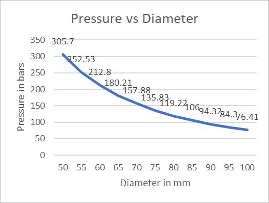
Table -1: Forgenerating60tonsofloadmaximum pressureneededwithdifferentdiameters
Chart -1:DiametervsPressure
Aswecanseefromthegraphthatasthediameterincreases thepressurerequiredtocreatethe60tonsloaddecreases.
And as the diameter decreases the pressure required to createthe60tonsloadincreases.
2.2 Calculations of load required for bendingaplateinVshape.
Vbendingformula:- P = C*B*t2*tmax
L
Where;C=coefficientofbending 1.5(L=5*t)
1.33(L=8*t)
1.2(L=16*t)
B=bendinglengthmm t=sheetthickness
tmax=tensilestrengthfromdesigndatabook.
Ex.1T=10,tmax=420Mpa,B=40,L=80 byusingvbendingformula
P=C*B*t2*tmax/L
P=1.5*40*100*420/80
P=27.9tons
P=28tons
Ejectorpad=bufferejection
Ejectorpad=0.3*p =0.3*28=8.4tonns
Totalload=Ejectorpad+P =8.4+28
Totalload=36.4tons.
Table -2: Load required to bend the plate with varying length
Table -4: Load required to bend the plate with varying width
Chart -2:LOADvsLENGTH
Table -3: Load required to bend the plate with varying thickness
Chart -4: LOAD vs Thickness


3. DRAWING

Chart -3:LOADvsThickness
4. ANALYSIS
Wehaveperformedanalysisontheframeofthehydraulic pressmachinebyapplying60tonsload.
Andwecame toknowthat theforce requiredto bend the plateisapprox.equaltotheforcerequiredforbendremoval.
REFERENCES
[1] Jarmai. K and Farkas.J. “Optimal design of Hoist structure frame”. Department of Mechanical Engineering,UniversityofMiskolc,Hungary.May2003


[2] Khurmi. R.S and Gupta. J.K (2005),”A Textbook of MachineDesign”,EurasiaPublicationHouseLtd.14ttth Edition.
[3] V. B. Bhandari, (2009),” Design of Machine Element”, TataMcGraw-HillEducation.
BIOGRAPHIES
RohanPanage

Professor at Dept of Mechanical Engineering, PVG’sCOET PUNE, Maharashtra,India.


EmailId: rohanpanage007@gmail.com
KshitijAsar
BE Scholar at Dept of Mechanical Engineering, PVG’sCOET PUNE, Maharashtra,India
EmailId:asarkshitij@gmail.com ShubhamChaudhary
BE Scholar at Dept of Mechanical Engineering, PVG’sCOET PUNE, Maharashtra,India.

EmailId: shubhamcc22@gmail.com
TusharSonawane
5. RESULTS

6. CONCLUSIONS
As the maximum principle stress is less than the ultimate tensile stress and the total deformation is within the specifiedlimits.Hence,thedesignis safe
BE Scholar at Dept of Mechanical Engineering, PVG’sCOET PUNE, Maharashtra,India
EmailId: sonawanetushar561@gmail.com