Vice Cum Bender Machine
1Student of Mechanical Engineering Department, Buddha Institute of Technology Gida, Gorakhpur, U.P., India
2Student of Mechanical Engineering Department, Buddha Institute of Technology Gida, Gorakhpur, U.P., India
3Student of Mechanical Engineering Department, Buddha Institute of Technology Gida, Gorakhpur, U.P., India
4Assistant Professor, Dept. of Mechanical Engineering, Buddha Institute of Technology Gorakhpur, U.P., India

Abstract - Objective of this project is to develop a vice cum bender machine that is use to bend metal strips in workshop and hold the work piece also. The motive of this project is to design and construct a portable vice cum bending machine. This machine is used to bend metal strips into curvature and the other curve shapes and when there is need to hold, it used as vice. The machine’s size is very appropriate for portable work. This machine is totally made by mild steel. Along with, it is easy to be carried and used anywhere at any time. It reduces human effort and also needed less skill to utilize this machine, that are designed manually operated vice cum bender machine with use of screw rod, bearings, slider and support (frame). This machine is manually operated &objective is to increase accuracy at cheap prize without affecting the bending productivity and also for vice with feeding specimen. This machine works on simple screw thread mechanism and roller instead of complicated design. Due to its portability, it can be used by small workshop or fabrication shop. Vice Cum Bender machine is used as common too in workshops that is used to bend a metal and hold it for cutting or other operation.
Key Words: Bending, Vice, Screw Rod, Portable, Fabrication, etc.
1.INTRODUCTION
Duetoincreaseinglobalization,itisverynecessaryforthe manufacturertofabricategoodshavinghighestaccuracy& integrity. In fabrication, Metal Bending and Holding is usually used as a surrogate method for casting or forging operations. Since it is associated to human being, it is compulsorytodesignthejointwith priorattentivenessto safetyofitsclient.Therearemanyproblemscomesduring bendingofmetallicstrips.Thereasonthatproblemisarisen duringthisprocessissincethemetallicpiecesrequirealot ofpressure,strengthaswellasaccuracytobebent.There are many machines to be used to achieve this but it is expensive.Thismachineisusedtobendmetalstripsandbar intocurveandtheothercurvatureshapesandwhenthereis needtohold,itusedasviceandfeedworkpiecealso.This construction is more user-friendly to everyone, relatively affordable,extremelyusefulanditwillfillwithfeelingsofjoy and satisfaction the people who want to spend their time productively.
2. LITERATURE SURVEY
Power regulated sheet bending machine & manually regulated sheet bending machine are utilized for manufacturing of pipes. It involves limitations too, of manuallyregulatedbendingmachine.Productivitythrough power regulated bending machine is higher from the outcomes of paper [1]. In this operation, Pipe bending mechanism has been used in fabrication and design & developmentofabicycle.Theutilizationofbentpipesisin frames,barricades,handleofbicycle.Apartfromthis,bent pipes are uses in most of industries as air conditioning, boiler tubes, off-road, power generation, automotive, ship building, furniture, railroad and agricultural equipment, aircraft etc. In countries like India, the physically driven machinewillimpactindevelopment&advancementofthe economy and employment of nation due to competent humanpower.Therefore,suchsystemhasapivotalrolein countryside as a result in Asian countries people are struggling with electricity cut-off throughout most of the days. [2]. Hydraulic tools have vast usage in different automobilefields.ForadjustingthechairsinBarber’sshop andindentalclinicsthesehydraulicequipment’sareused. Further to bend pipes, strips, bars and rods Hydraulic bending machine is the appropriate equipment. The strip, bar&pipethathastobebentiskeptbetweentherollers.We applyforceonthepipeandbendittothedesiredanglerely ontherollerusedbyusinghydraulicjack.Hydraulicbending machine has less expenditure, portable and flexible in comparison to those about which we talked previously. Hence it is better to substitute the present standard machines by hydraulic pipe bending machine [3]. Author informed in previous years that pipe bending machine is usedinindustryaswellasinhouseholdpurposeforbending thepipeundertherequiredanglesanddimensions.Inthe hydraulic pipe bending machine, it has a good process as comparedtotheheattreatmenttechnique [4].
3. RESEARCH GAP
Theimprovementinsomefields,inthisprocesslike reductionofcost.
High flexibility because of different types of parts canbebend.
Unevenshapedofbar&stripcanbegeneratedby otherbendingm/c.
Thesizeofthismachineisveryconvenientbywhich itisportable.Duetoitsportability,itcanbeusedin smallworkshoporfabricationshop.
4. PROBLEM STATEMENT
Themainreasontochoosethisprojectistosimplify the operation of bending and make vice in this machinebecausematerialslipsduringprocess.
The main problem is that the machine already availablearemostcostlyandheavy.
The study shows bending of thick strip or bar executehigherloadoncenterrollerofmachine.As the thickness of strip or bar increases the load actingonthetoprolleralsoincreases.
5. OBJECTIVE OF THE WORK
Theobjectiveofourworkistofabricate,manufactureand designaVicecumBenderMachineforlightduty.Theeffort istocombineintoasinglemulti-taskingmachinewhichis effortless to manage and performs the aforementioned operationsefficientlywhichisbetterofthetwomachines.
Infewwords,theobjectivesoftheworkareasfollows:-
To fabricate and design a bending machine for metalstrips.
Toutilizeunskilledworker.
To reduce the duration and expenditure of the operation.
To construct a machine competent of holding, feedingalongwithbendingmetalstrips&bar,pipes androdsofvariousdimensions.
To construct this m/c on a simple working principle.
To formulate the machine comfortable & ease to operate.
Tomakeitconvenient&transferable.
Takingtheseinaccount,thewholeworkwasshiftedfurther, alsoeffortsweremadetoadheretothetargetasrigidlyas feasible.
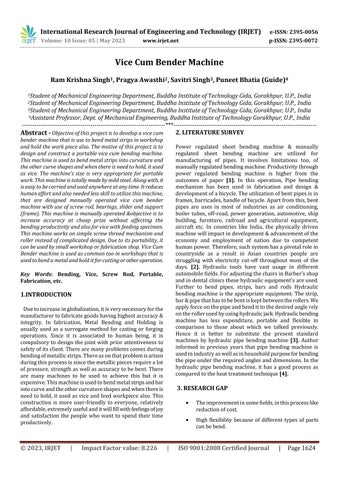
6. METHODOLOGY
7. DESIGN
7.1 Designing Process
Theprocessofdesigningisanecessarypracticeinapplied innovation&creativity.Differentdesignprocedurescameto be elucidated to help out assemble to assault over inbuilt problems description is indistinct for which numerous solutionsexist.Severalofthisdesignprocessarebeneathas youcanobserve.
Recognitionofneed:Itincludesidentificationbysomeone that an issue exists for which some rectifying measures ought to be taken. The problem perhaps recognizes few defectsintheexistingmachineryoraneedofnewproductin themarket.
Definition of problem: It embrace through requirement of the product to be prepared. Physical,practicalorfunctionalfeatures,costprice, propertyorquality,andoperableperformancesare involvedinthesespecifications.
Synthesis: In this phase we are developing preliminary (basic) ideas regarding the topology andconfigurationofthedifficulty,i.e.,regardingthe structure&extentandassociationofdistinctparts intheproduct.Aprototypemodeliscreatedinthis stage.
Analysis: In this phase a prototype model is analyzedbygivingdifferentlimitedsituationsand restrictions, subjecting the model to different conditionsandloadstoperformstudyoffeasibility. Thedesignisreturnedbacktothesynthesisphase, iftheproductblunderatthisstage.
Evolution: The final products of the inspecting period is compared with terminal stage. If they requireabittransformation,thenthedesignisonce againregressedbacktotheblendingperiod.
Presentation: It contains authentication of the design by signify of drawings, component specifications, charge of elements, scenes, toughnessandsoon.
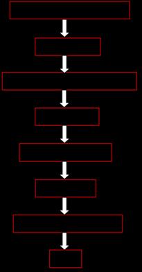
7.2 Component
7.3 Calculations
Consequentfundamentalpruningprocessonametalsheet, constituents can be twisted to give it a specific structure. Curvingofsegmentsrelyuponcomponentqualitiesatthe position of the bend. To attain bending, the functional element needs to be subjected to two considerable intensities;thereisnoslip becauseofthe resistanceforce duetowhichweapplybendingforcethroughtheroller,then the deflection occurs in the metal bar or in strip and the torque is generated through the handle due to which the materialmoves.
Where,
F=onrollerforceisapplied;
L=gapbetweenroller;
μ=0.4Nm-1i.e.,frictionalforce;
a = interspace from the no-slip point to departure zone (assumea=L/2);
T=torqueappliedtorollers;
r=rollers’radius;
ho,hf=widthofthestripbeforeandaftertimet.
Toincreaseanddecreasethethicknessofanymetalstrip orbar,thereshouldbeatleasttworollersareusedthrough which its thickness is reduced by rolling process and converteditintoacurvatureformweshouldusethreeroller mechanisms. When a ductile material is bent then the tensionoccursinitsuppersurfaceandcompressionin its lowersurface.
A. Design of Chain drive:
Specifications:
D1:drivingsprocket’sdiameter
D2:drivensprocket’sdiameter
L=chain’slength =Ln*P
Z1:Numberofteethondrivingsprocket=19
Z2:Numberofteethondrivensprocket=19
a: center distance between driving sprocket and driven sprocket=301mm
where,
Ln:numberoflinks
P:Pitch=0.25inch=6.35mm
Ln=78.30mm
L=78.30*6.35
L=497.205mm
D=30mm
D=D1=D2=30mm
B. Design of power screw Specifications
µ:co-efficientoffriction=0.15
do:minordiameter=6.04mm
W:weightoftheroller=2.5Kg=24.525N
dc:majordiameter=7.4mm
P:pitch=6.35mm
Torquerequiredliftingtheload:
Lead=pitch(singletrapezoidalthread)
Torquerequiredtoloweringtheload
Lead=6.35mm
T2=4.47N-mm
d= thatistheloadactingononescrewrod
d=6.72mm
Thescrewisself-lockingbecausethereducingloadis+ve.
C. Force analysis
Specifications = Highest torque appropriate for a cylinder rolling
s: Output limit of material=218 N/mm2 (from data hand book)
B:Twistedshieldmaximumthickness=40mm:Rolledsheet widthinmm
Torque required raising the load (for 1 revolution of one screw)
Mt=ydA=2
Forthickness
Whenconsideringthedistortionoftheproduct,there T is strengthening and to customize the equation the reinforcementco-efficientKisintroduced
T1=20.45N-mm
Itistheforceactingonscrew.
Mt-mm
Totaltorque=20.45*54
Intheaboveformula
K:reinforcementco-efficient=1.15
Totalforce=2mm
Mt=10028N-mm
Forthickness=3mm
Mt=22563N-mm
Forthickness=4mm
Mt=40112N-mm
D. Force condition
The force position is acting while rolling steel strip. The supportingF2ontherollstripcanbeacquiredthroughthe followingformula,accordingtotheforcebalance.
F=theanglebetweendefinedline001and002
a=lowerrollercenterdistanceinmm.
d min = minimum diameter of the rolling strip in mm = 388mm
d2=lowerrollerdiameterinmm=62mm
R=rollingradiusofneutrallayersinmm
R=0.5dmin
R=0.5*388=194mm
F2=115.63N
ThepressureforceF1thatisdevelopedbytheupperroller, affectingontherollingstrip,accordingtoforcebalancei.e.,
F1=2F2
F1=2*115.63
F1=206.91N
F2=260.3N
F1=2F2
F1=2*260*
F1=460.98N
F2=462.90N
F1=2*F2=2*462.90*
F1=828.31N
E. Calculation of driving Torque:
Thelowerstriprolleroftherollingmachineisthedriving roller and the driving torque is utilized to conquer the deformation torque Tn1 and friction torque Tn2 on the lowerroller.
Tn1=1601.13N-mm[for2mmMSstrip] whichcanbecalculatedasfollows.
Intheaboveformula,
f=co-efficientofrollingfriction=0.008*103mm
=co-efficientslidingfriction
d1,d2=upperrollerandlowerrollerdiameter(mm)
D1,D2=upperrollerandlowerrollerneckdiameter(mm)
Di=0.5di(i=1,2)
D1=0.5d1
D1=0.5*62=31mm
D1=D2(samesize)
Tn2=0.008*103[206.91+2(115-63)]
Tn2=3508.07N-mm
TotaltorqueT=Tn1+Tn2
T=1601.13+3508.07
T=5109.206N-mm
F. Shaft analysis
Specification, Tensilestrengthofthematerial(Sut)=770N/mm2
Yieldstressofmaterial(Syt)=480N/mm2
fs=factorofsafety
ShaftMaterial=steel(FeE480)
145N/mm2
Calculatingtorque,
T=0.18Sut =0.18*770
T=139N/mm2
128<149N/mm2, Hencedesignissafe.
8. WORKING
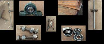
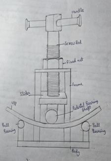
Screw rod is a main component which is fixed on a top of machineframeincentreandbyhandleitisoperated.Onthe bottomsideofscrewrod,asliderisattached.Andbelowthe sliderpedestalbearingisjointinwhichashaftislocatedand run by handle. With the help of nut bolt ball bearings are attached both side of frame on a certain height at fixed distancefromcentre Twohandlesareusedoneforscrew rod and other for shaft. Screw rod and nut mechanism is used to applied force on work piece which is to be bend. Work piece is hold between ball bearing and shaft of pedestal bearing. When work piece is to be bend then graduallyforceisappliedbyscrewrodandworkpiecedoes to&fro motionwiththehelpofpedestal bearingshaft by handle.Ballbearingisusedasarollermechanismforfeeding theworkpieceifneeded.
10. SIGNIFICANCE
VeryusefulinFabrication
Curvedpartsareeasilymade
Supportsavarietyofsoftmetals
Portable
Lowinitialcost
Lowmaintenancecost
SimpleDesign
11. EXPERIMENTAL RESULTS
Resultsfor5mmthicknessofmetalstrip:S.No.
Costofproject:-
12. CONCLUSIONS
This project is to increase accuracy at low prize withoutaffectingthebendingproductivityandalso usedasvicewithfeedingtheworkpiece.
Tofabricatemachinesinlesspossibleexpenditure was one of the main purposes. We preferred to utilize Screw Rod over the more expensive hydraulic jack and the rolling feed and bending pressure as well are given by human effort, that bringsdownthepricefurtherinourdesign.
Theoutcomeacquiredbyconceptualestimationand theoneacquiredfromsimulationareapproximately similar with one another and this results in authentic design. This machine is completely a mechanicaltool.Thus,theregardedworkpieceand itsmeasurementsaresufficientandthefabricated machine can function effectively with the aforestatedspecifications.
Throughthismachinemaximum20mmthicknessof metal strip can be bended & 25mm of bar for a maximumlengthof0.6m.
Whenitisusedasavicethenthemaximum20feet length of strip or bar can be feed with maximum thickness150mm.
ACKNOWLEDGEMENT
Cooperation&coordinationhelpsincompletionofanywork, and together efforts of some sources of knowledge. We wouldliketoexpressourspecialthanksofgratitudetoour guideMr.PuneetBhatia,whohelpedusinfabricationofthe
model.Andalso,wearethankfulfortheassistcontributed byMechanicalEngineeringDepartmentofBuddhaInstitute ofTechnology,GIDA(Gorakhpur)intermsofmachinesand equipment.
REFERENCES
[1] P.S.Thakare,P.G.Mehar,Dr.A.V.VanalkarandDr.C.C. Handa,"Applicationswithanew6-dofbendingmachine in tube forming processes". Jose Vitor Souze, InternationalJournalofMachineTools&Manufacture, 2002.
[2] V.SenthilRaja,R.Maguteeswaran,C.Karthik,S.Rajarajan andD.ShanmugaVadivel,“Experimentalandnumerical modellingofbucklinginstabilityoflasersheetforming”, InternationalJournalofMachineTools&Manufacture, 2002.
[3] H.A.Hussain,M.SohailPervez,Md.NaushadAlamand Atul. P. Ganorkar, The Bending of Curved Pipes With VariableWallThickness.JournalofAppliedMechanics, Vol.70,pp.253–259,2003.
[4] S. A. Mohan Krishna, P.E. Piping Handbook (7th Ed.). NewYork:McGraw-Hill.ISBN,2000.
[5] Prashant P. Khandare, Dhiral N. Patel, Mayur K. Aher, Ravi S. Parbat and Prof. Swapnil S. Patil, Effect of internal pressure and shape imperfections on plastic loads of pipe bends under in-plane closing moment, EngineeringFractureMechanics105(2013)1–15.
[6] MaheshGadekarandMr.Amol,“DesignDataHandbook forMechanicalEngineersinS.I.andMetricUnits”,ISSN: 2321-8169,Volume:3,Issue:8,August2015,PP5132–5135.
[7] K. Mahadevan and K. Balaveera Reddy, “Design & DevelopmentofThreeRollerSheetBendingMachine”in InternationalJournalonRecentandInnovationTrends in Computing and Communication, CBS Publishers & DistributorsPvt.Ltd,ISBN:978-81-239-2315-4,Fourth Edition:2013.
[8] C.Vinod,P.C.KumarandCH.S.Reddy,EffectofCurved BarPropertiesonBendingofCurvedPipes.Journalof AppliedMechanics,Vol.68,pp.650–655,2001.
[9] DesignofMachineElementsbyV.B.Bhandari,intership live,2012.
[10] Hiroyukigoto,Kenichiru,Hidenobusaitro,Yuuishikura andYutakatanaka,“ProductivityAnalysisofManually OperatedAndPowerOperatedSheetBendingMachine: A Comparative Study” in International Journal of Engineering Research and Applications (IJERA), ISSN: 2248-9622,Vol.2,Issue2,Mar-Apr2012,PP.111-114.
[11] Z. Hu, R.Kovacevic, M.Labudovic, “A New Model in Design and Manufacturing of Mobile Hydraulic Pipe BendingMachineinIndustry”inInternationalJournalof Engineering Research & Technology (IJERT), ISSN: 2278-0181,Vol.3Issue1,January–2014,PP27062713.
[12] Nayyar,P.E.,MohinderL."A1".InMohinderL.Nayyar, “Experimental Design and Fabrication of a Portable Hydraulic Pipe Bending Machine” in International JournalofDevelopmentResearch,ISSN:2230-9926,Vol. 4,Issue12,pp.2681-2684,December,2014,PP26812684.
[13] ChristoMichael,A.R.Veerappan,S.Shanmugan,“Studyof Portable 3 Roller Pipe Bending Machine” in International Conference on Emerging Trends in Engineering and Management Research, ISBN 97881932074-7-5,23March2016,PP624-630.
[14] Cherniy.V.P.,“DesignandDynamicAnalysisofHydraulic PressMachineforSheetnotPipebendingOperations”in InternationalJournalofEngineeringTechnologyScience and Research, ISSN:2394-3386, Vol 4, Issue 12, December2017.
[15] Cherniy. V. P., “Design and Development of Bicycle Integrated Pipe Bending Machine” in IOSR Journal of MechanicalandCivilEngineering(IOSRJMCE),e-ISSN: 2278-1684,p-ISSN:2320-334X,2014,PP24-28.
BIOGRAPHIES
Ram Krishna Singh is an Engineering student who have done Diploma in Mechanical Engineering Production and Bachelor in Technology in MechanicalEngineering.

Emailid:
ramkrishnasing676@gmail.com
Contact:+918400895717