End-Effector System for Semi-Solid Material-Based Additive Manufacturing
Sameer Bhuvaji1, Anmol Khose2, Prathamesh Bhalerao3, Yash Jadhav4, Girish Ghadage5 , Mr. Vivek Diware6
1,2,3,4,5 Student, B.E. Mechanical Engineering, D. Y. Patil College of Engineering, Akurdi, Maharashtra India
6 Assistant Professor, Dept. of Mechanical Engineering, D. Y. Patil College of Engineering, Akurdi, Maharashtra, India ***
Abstract - Significant advances have been made in various fields including advances in additive manufacturing and fabrication of complex geometries using semisolid materials. This paper presents a detailed review of the design and fabrication of an end-effector system specifically for semi-solid material-based additive manufacturing is provided. The focus of this study is to develop an efficient hopper system for semi-solid and controlled material distribution in addition to incorporating an auger shaft into the system to facilitate mixing and control of material flow through the nozzle. To validate the performance of the proposed system, experimental measurements were carried out to determine the maximum flow rates under operating conditions, theoretical calculations were also used to analyze the flow behavior and predict how the large flow is expected. Experimental and theoretical results were then compared to verify the accuracy and reliability of the system. The findings of this study demonstrate the successful design and operation of an end effector system capable of efficiently handling semisolids for additive manufacturing applications. Experimental and theoretical validation demonstrates the system's ability to achieve a constant mass flow rate, precise control, and reliable fabrication. New avenues have beenopenedfor raw materials.
Key Words: Additive Manufacturing, 3D Printing, Auger Shaft, Hopper, PLA
1. INTRODUCTION
The field of additive manufacturing has witnessed an extremely good increase in current years, revolutionizing conventional production methods by allowing the fabrication of complicated geometries with greater performance and accuracy. In particular, the usage of semi-solidmaterialsinadditivemanufacturinghasgained enormous interest due to its potential to supply components with improved mechanical intricacies. However, achieving precise control over the shelling out and going with the flow of such substances poses precise challengesthatnecessitatetheimprovementofspecialized endeffectorstructures.
This studies task makes a specialty of the design, fabrication, meeting, and testing of an end-effector

mechanism specially tailor-made for semi-solid materialbasedadditivemanufacturing.Thekeygoalistoincreasea system capable of efficiently handling the meting out and float of the semi-solid material at the same time as ensuringconstantandmanageddepositionviathenozzle.
1.1 Design and Modeling
The preliminary section of the mission involved the design of a hopper-style layout for the end effector. The hopper layout turned into important as it determines the slope and length of the hopper, which in flip impacts the material waft traits. With the entire period of the entire systemconstantat425mmlengthandthediameterofthe nozzle set at 25 mm, the layout considerations have been based on optimizing the hopper's dimensions to gain the desiredoverallperformance.
The subsequent step was designing the auger shaft, whichplaysavitalpositioninblendingandregulatingthe flow of the semi-strong material through the nozzle. The diameterandlengthofthehoppersystemdeterminedthe calculatedpitchoftheaugershaft,makingsureofefficient sedimentblendingandcontrolledflow.
Tofacilitatethedesignmethod,AutodeskFusion360,a complete computer-aided design (CAD) software, become applied to model the entire assembly. This 3-D version served as a virtual representation of the end effector mechanism, allowing thorough visualization and analysis ofitsadditivesearlierthantheproducinglevel.
1.2 Manufacturing and Testing
The fabrication technique uses 3D printing techniques to convert the virtual design into a physical prototype. This method provided the benefit of speedy and effective manufacturing, allowing for iterations and changes based totallyontheanalyticalconsequences.
Subsequently, the prototype was subjected to rigorous experimental testing to evaluate its overall performance. The experimental statistics were compared with theoretical values obtained through calculations, allowing the validation of the end effector system. This validation
manner helped verify the system's capability to attain the favored mass flow quotes and established its reliability within the semi-solid material-based additive manufacturingtechnique.
The outcomes of this study undertaking keep massive implications for the additive manufacturing enterprise, especially within the domain of semi-solid material processing. The development of a specialized end effector system capable of exactly controlling the allotting and glideofsemi-solidmaterialsopensupnewpossibilitiesfor fabricating intricate additives with improved mechanical accuracies. By providing a comprehensive exploration of the layout, fabrication, and validation system, this study contributes to advancing contemporary additive manufacturingtechniquesforsemi-stablesubstances.
2. COMPONENTS
2.1 Hopper
The hopper serves as the field for the semi-solid material used within the additive manufacturing manner. It has a funnel-fashioned design and is fabricated from Carbon Steel to face up to the material's homes. The hopperpermitscontrolledandconstantdishingoutofthe material, making sure of a constant glide for layer-bymeans-of 3D printing. Its layout, together with the slope and length, is essential in optimizing the design with the flowcharacteristics.
2.2 Auger Shaft
Theaugershaftperformsanessentialtaskultimatelyin the end effector system because it allows the integration and law of the semi-solid material. It is housed in the hopper and driven by using a wiper motor. As the shaft rotates,itmixesthematerialthoroughly,makingsureofa homogenous composition. Additionally, the auger shaft regulates the mass drift flow of the material through the nozzle, contributing to unique manipulation during the printingmanner.
2.3 Wiper Motor
While no longer explicitly cited inside the preliminary undertaking description, the wiper motor is a vital elementintheendeffectorsystemforsemi-solidmaterialbased additive manufacturing. It is answerable for controlling the motion of the auger shaft, which helps maintain the cleanliness of the nozzle orifice. The wiper motor guarantees that the nozzle remains unobstructed, preventinganyabilitydisruption withinthematerial waft andmakingsureofsteadyprinting.
2.4 Nozzle
The nozzle is an essential part of the 3D printing procedure, chargeable for depositing the semi-solid material onto the printing floor in a desired shape. It is designed with a particular diameter (25 mm in this assignment) to regulate the go-with-the-flow and attain the desired layer thickness. The nozzle's role is to precisely manage the deposition of the material, making sure of accurate and controlled fabrication of the desired geometries.
2.5 End Cap
The end cap serves as the closure for the hopper, preventing the material from overflowing out of the system. It is designed to securely seal the hopper to preserve managed surroundings for the material. By preventing material spillage or leakage, the end cap guarantees the integrity of the additive manufacturing system and avoids any disruptions that could affect the qualityofthematerialadditives.
Overall, everything in the end-effector system has a particular characteristic related to dealing with, manipulating, and deposition of the semi-solid material. Together, they work in tandem to enable the proper and controlledadditive manufacturingof intricategeometries, contributingtotheachievementoftheproject.
3. WORKING
i. Material Addition and Inlet:Thesystembeginsbyway of adding the semi-solid material into the hopper volume. This can be carried out thru an inlet pipe, making an allowanceforguideloadingorpumpedinput.Thehopper serves as the container for the material, ensuring a managed and steady delivery for the additive manufacturingmethod.Thematerialisintroducedintothe hopper, wherein it is stored and organized for the next processing.
ii. Mixing Action:Oncethematerial isinsidethehopper, the auger shaft comes into play. The auger shaft is
designed to rotate, offering a mixing action to the semisolidmaterial.Thisblendingmovementisvitaltopreserve the material’s favored consistency and prevent it from sticking to the hopper's internal surfaces. The rotational movement of the auger shaft guarantees thorough blending, ensuring a homogenous composition of the materialinsidethehopper.
iii. Auger Shaft Speed and Mass Flow Rate:Thevelocity of the auger shaft plays a massive position in regulating the mass flow rate of the material via the nozzle. By adjusting the rotational velocity of the auger shaft, the system can manipulate the flow at which the material is dispensed through the nozzle. Higher speeds commonly result in improved waft costs, even as slower speeds can lessen the flow rate. This capability lets in for particular control over the material deposition at some point of the additive manufacturing manner, allowing the advent of trickygeometrieswithaccuracy.
iv. Computer Control and Shape Creation: The end effector system is generally PC-controlled, providing a high degree of precision and versatility in shaping systems. The PC interface permits the regulation of the ratedrateoftheendeffector,whichdeterminestherateat whichthematerial isallotted. Additionally,thevelocity of the auger shaft can be adjusted to in addition refine the management of the material flow. By manipulating these parameters within the X, Y, and Z axes, the system can create pathways with thefavoredshapesanddimensions, layerbylayer.
In summary, the end effector system operates by using introducing the semi-stable material into the hopper, which undergoes blending via the rotation of the auger shaft. The velocity of the auger shaft regulates the mass flow rate of the material through the nozzle, even as PC managementallowsfortheparticularshapingofobjectsin three dimensions. This coordinated functioning of the system enables controlled and accurate additive manufacturingofcomponentsusingsemi-solidmaterials.
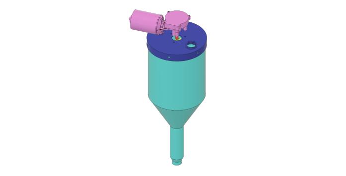
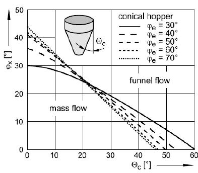
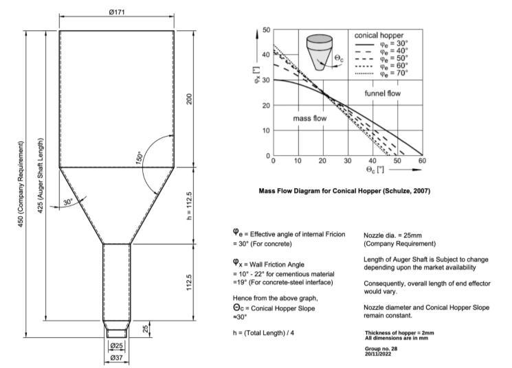
The effective attitude of internal friction (Θe) represents theslopeorshearelectricityofthematerial.Forconcrete, the literature survey yielded a steady cost of 30° for this attitude[2].Thewallfrictionperspective(Θx)referstothe angleatwhichthematerialslidesagainstaparticularwall surface end. The literature indicated a constant value of 19° for the wall friction angle among concrete and metal interfaces [4]. Based on the Mass Flow Diagram, the conicalhopperattitude(�c)becamedeterminedtobe30°, representingtheangle betweenthevertical routeandthe tiltedexitwall.
Thedesignofthehopperfortheendeffectorsystembegan with figuring out three key angles: the effective angle of internal friction (Θe), wall friction attitude (Θx), and conical hopper perspective (�c), primarily based at the Mass Flow Diagram for conical hoppers via Schulze (2007).
Other variables along with the full period, extruder diameter, and internal diameter above and beneath the hopper cross-sections have been additionally calculated. The general duration became supplied by means of the
organization as a requirement and set to 450 mm, whilst theextruderdiameterturnedintofixedat25mm.
An empirical relation between the height of the hopper and the overall length of the frame become determined throughout the research segment. It became discovered that the peak of the hopper (h) is the same as one-fourth ofthewholelengthofthebody.Applyingthisrelation,the peakofthehopperchangedintocalculatedash=450/4= 112.5 mm. It become also decided that the height of the hopper (h) is identical to the period of the body underneaththehoppercross-segment.
Considering the inner diameter of the nozzle as 25 mm and providing a 2 mm clearance, the internal diameter of the auger shaft was selected as 35 mm. This sizing of the auger shaft changed primarily based on the necessities of thenozzle'sdimensions.
Based on these layout calculations and dimensions, the hopper turned into modeled using Autodesk Fusion 360, which allowed for the visualization and analysis of the hopper'sgeometry.
Thepitchofanaugershaftreferstothedistancebetween corresponding factors on adjacent threads. It is a critical parameter as it determines the rate at which the material istransportedalongtheshaft.Byhavingthepitchidentical to the diameter, the layout ensures that the material is successfully blended and regulated as it moves via the augershaft.

Relation
Having a steady pitch and diameter simplifies the layout and fabrication method for the auger shaft, because it eliminates the need for complicated calculations or customizations. It additionally lets in for easier manufacturingandassemblyoftheceaseeffectordevice.
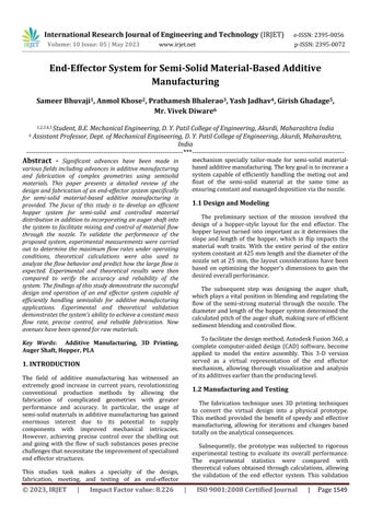
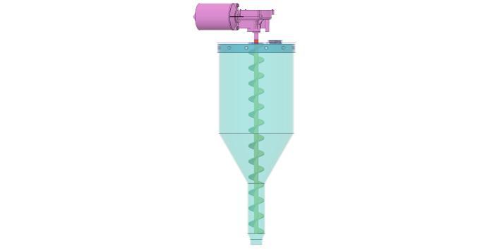
Fig -3:CADModeloftheEnd-EffectorSystem
By considering the required angles, dimensions, and empirical family members, the hopper layout turned into correctly formulated, permitting the following ranges of fabricationandcheckingoutfortheceaseeffectordevice.
5. DESIGN OF AUGER SHAFT
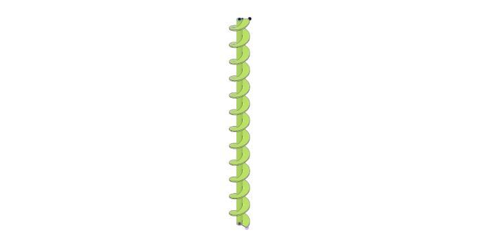
The layout of the auger shaft for the end effector system consists of figuring out the diameter and pitch. In this project, the auger shaft diameter changed into decided to 35mmbasedonthenozzle'sinternaldiameteranda2mm clearance.
To calculate the pitch of the auger shaft, an empirical relation become used. In this case, the pitch was decided tobeidenticaltothediameteroftheshaft[4].Thisimplies thatthegapbetweenadjacentthreadsoftheaugershaftis thesameasthediameteritself.
-5:CADModeloftheAugerShaft
By figuring out the diameter as 35mm and setting the pitch equal to the diameter, the design of the auger shaft guaranteesefficientmixingandmanagedmasswaftrateof the semi-stable material at some stage in the additive manufacturingmethod.
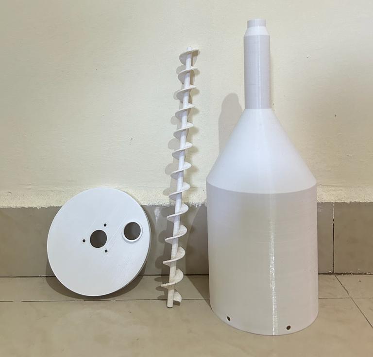
6. MANUFACTURING
For the manufacturing of the end effector device, the decisionwasmadetomakeuseof3-Dprintingtechnology for prototyping purposes. PLA (Polylactic Acid) turned intoselectedbecauseofthematerial for3-Dprinting.PLA is a famous thermoplastic polymer known for its biodegradability, low toxicity, and ease of use in 3D printing packages. It is derived from renewable sources, which include cornstarch or sugarcane, making it an environmentallyfriendlypreference.
Due to the height of the model being near half a meter, it turnedvitaltodiminishthedesigntomakecertainitcould match the obstacles of the three-D printing workspace. A scaling aspect of 25% became carried out to the version,
reducing its usual dimensions while keeping the design proportions.
The use of 3-D printing allowed for the introduction of a bodily prototype with complex information and precise geometries.Thelayeredadditivemanufacturingprocessof 3-D printing enabled the fabrication of complex shapes and internal structures that would be hard to obtain with theuseofconventionalproductiontechniques.
The general printing time for the scaled-down model became approximately 1 day, 2 hours, and 17 minutes. Thisdurationrepresentsthecumulativetimerequiredfor printing all of the layers of the model, deliberating the layer peak and printing pace settings. During the printing procedure, the 3D printer systematically deposited and fused PLA filament layer via layer till the entire model turnedintoform.
By employing 3-D printing technology and deciding on PLA as the printing material, the production process for theendeffectorsystemchangedintogreen,rate-effective, and allowed for fast new release and refinement of the layout. The resulting prototype supplied a tangible representation of the system, facilitating further checking out and validation of its capability and overall performance.
delicate nature of the scaled-down 3D published auger shaft, which could not resist the trials of managing actual concrete material. Additionally, the hopper frame, being made of PLA, changed into no longer appropriate for holding dense, wet concrete. The experimental manner worried filling the hopper with dry first-class sand and rotating the auger shaft as soon as, similar to one entire revolution. This rotation became intended to simulate the combination and meting out the process of the semi-solid material. The experiment repeated for 5 instances, ensuring sufficient factors for analysis and lowering the effectofanycapacityinconsistencies.
6. EXPERIMENTAL AND THEORETICAL ANALYSIS
To compare the functionality and overall performance of the end effector device prototype, experimentation become carried out with the usage of dry fine sand as an alternative material. This become necessitated by the
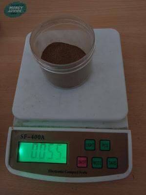
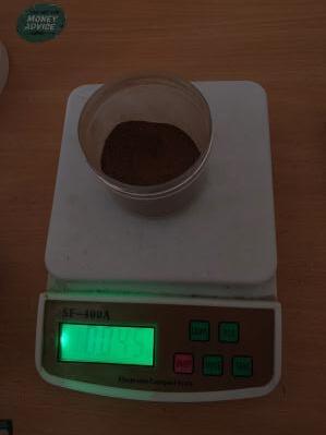
After every check, the weight of the disbursed sand material becomecautiously measuredandrecorded.This allowed for the quantification of the mass glide price achievedbytheendeffectorsystematsomestageineach rotationoftheaugershaft.
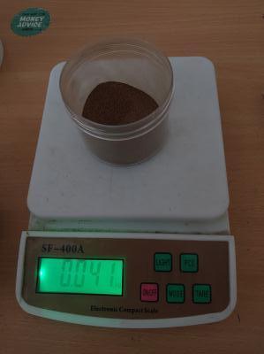
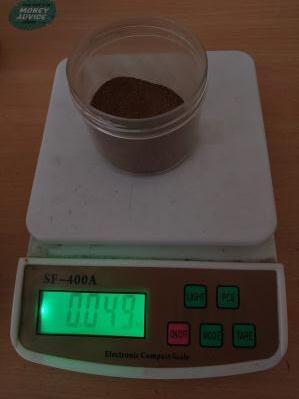
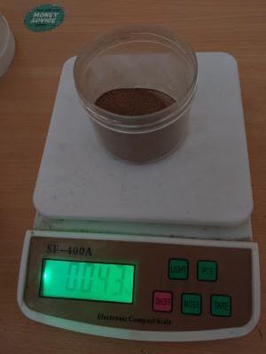
To decide the average mass flow charge, the recorded weightsfromthefivetestshavebeensummedanddivided via the number of assessments conducted. This common practice represented the experimental mass flow rate performedbythesystem.
By evaluating the experimental mass flow with the flow rate with the corresponding theoretical values, the performance of the end effector system may be verified and assessed. The theoretical values had been received through calculations primarily based on the layout parameters, consisting of the dimensions of the hopper, auger shaft, and nozzle, aswell as the rotational pace and pitchoftheaugershaft.
The comparison of the experimental and theoretical mass go with the flow prices allowed for an evaluation of the system's efficiency and the accuracy of the layout calculations. Any discrepancies among the experimental and theoretical values ought to provide insights into potential regions of improvement or optimization for the endeffectorsystem.
Overall, the experimentation phase provided valuable statisticsontheshellingout oftheoverall performance of the end effector system using dry high-quality sand instead material. The outcomes received through this checking-out manner contributed to the validation and verificationofthesystem'scapabilityandtheevaluationof its suitability for semi-stable fabric-based totally additive manufacturingapplications.
7. RESULTS
Theexperimentalandtheoreticalcalculationsforthemass flow rate of the end effector system were conducted, and the obtained values were compared. The experimental mass flow rate was found to be approximately 46.6 grams/sec (at 60 RPM), while the corresponding theoretical value was calculated to be around 43.8 grams/sec (at 60 RPM). The small difference between the experimental and theoretical values indicates a high level ofaccuracyandreliabilityinthedesignandfabrication of the end effector system for semi-solid material-based additivemanufacturing.
8. CONCLUSION
In this paper, we offered the layout, fabrication, and experimental validation of an end effector system for semi-solid material-based additive manufacturing. The system comprised a hopper for material storage and a mainlydesignedaugershafttocombineandmodifythego with the flow of the material through the nozzle. The layout parameters for the hopper, which include the effective angle of inner friction, wall friction angle, and conicalhopperperspective,weredecidedbasedtotallyon empirical members of the family and literature survey.
The auger shaft became designed with a diameter of 35mmandapitchequaltothediameter,ensuringefficient blendingandmanagedmassgowiththeflowrate.
Through the usage of 3-D printing technology, we efficiently fabricated a scaled-down prototype of the end effector system using PLA material. While the delicate nature of the auger shaft limited trying out with real concrete material, we carried out experiments with the usage of dry satisfactory sand rather. The experimental mass float rate turned into determined to be in near agreement with the corresponding theoretical rate, demonstrating the correct design and functioning of the ceaseeffectorsystem.
Theseoutcomesimplyahitcognizanceofaneffective end effector device for semi-stable material-based additive manufacturing. The design and fabrication process, coupled with experimental validation,have confirmed the feasibility and reliability of the proposed system. The findings of this observation make a contribution to the advancement of additive manufacturing technologies for the fabrication of complex geometries using semi-stable substances.
In future paintings, in addition, optimizations and upgradescanbe exploredtoimprovethesystem'soverall performance, including investigating alternative substancesforthehopperandaugershafttoenabletrying out with real concrete. Additionally, the system could be integrated into an entire additive manufacturing setup to explore its capabilities in fabricating elaborate structures andusefuladditives.
Overall, this research assignment has supplied precious insightsinto the designand fabricationofa cease effector system for semi-stable fabric-primarily based additive manufacturing, showcasing its capacity for numerous packageswithinthedisciplineofadvancedproduction.
REFERENCES
[1] A. Albar, M. R. Swash and S. Ghaffar, "The Design and Development of an Extrusion System for 3D Printing Cementitious Materials," 2019 3rd International Symposium on Multidisciplinary Studies and Innovative Technologies (ISMSIT), Ankara, Turkey, 2019,pp.1-5,doi:10.1109/ISMSIT.2019.8932771.
[2] Jo, J.H., Jo, B.W., Cho, W. et al. Development of a 3D PrinterforConcreteStructures:LaboratoryTestingof CementitiousMaterials.IntJConcrStructMater14,13 (2020).https://doi.org/10.1186/s40069-019-0388-2
[3] Zeleny, Petr&Růžička,Vojtěch.(2017).Thedesignof the 3D printer for use in gastronomy. MM Science Journal. 2017. 1744-1747. 10.17973/MMSJ.2017_02_2016187.
[4] JoãoTeixeira,CecíliaOgliariSchaefer,BárbaraRangel, Lino Maia, Jorge Lino Alves, A road map to find in 3D printinganewdesignplasticityforconstruction–The state of art, Frontiers of Architectural Research, Volume 12, Issue 2, 2023, Pages 337-360, ISSN 20952635,https://doi.org/10.1016/j.foar.2022.10.001
[5] Lobato, J.C.M. & Mesenda, Alexandre & Mesenda, Andre. (2014). Conical hopper design for mass flow –caseofstudyforredmudpowder.
[6] Fadeyibi,Adeshina&Osunde,Zinash&Gbabo,Agidi& Egwim,Evans.(2016).Designofsinglescrewextruder for homogenizing bulk solids. Agricultural Engineering International : The CIGR e-journal. 18. 222-231.