
Design and Development of Ackerman Steering System for Formula Student Vehicle
Shreyash Chougule1, Jotiba Avatade21Student, Department of Automobile Engineering, Rajarambapu Institute of Technology Islampur, Maharashtra, 415414 India
2Student, Department of Automobile Engineering, Rajarambapu Institute of Technology Islampur, Maharashtra, 415414 India

***
Abstract – In this paper, a steering system is designed for FORMULA BHARAT student vehicle, which adopts a rack-andpinion steering mechanism. Team planned to design and develop a custom steering design that not only provide high accuracy but also met our weight & budget norms. The theoretical modeling of the systems as well as the derivations of the optimal parameter values is presented here. By understanding the vehicle requirements first we finalized the Ackerman angle. Based on that angle the geometry of the Ackerman steering system and all the design calculations of the each component of the steering system are also presented.
Key Words: SteeringSystem,FormulaStudent,Ackerman Steering,RackandPinion
1. INTRODUCTION
As we are working on a national level project named FORMULABHARATinwhichthedesignanddevelopmentof aFormulaStudentracecarwastobedoneandforthatwe had the task to design and develop a Ackerman Steering System thatfacilitated thedriverto takesharpturns with less efforts or with less revolutions of steering wheel. To achievethiswedecidedtomodifytheconventionalsteering mechanism that is used in the normal round cars. The steering system of the car is rack and pinion based mechanismthatconvertstherotationalmotiongeneratedat thesteeringwheelintoalinearmotionattheendoftherack. ThedesignisbasedontherulebookofFORMULABHARAT 2019,accordingtowhichdrivebywireforbiddenandhence wehaveselectedasimplerackandpinionsystemwith no additional electrical or hydraulic help. Though the tracks usedforsucheventsareflatinnature,onemustaccountfor thenaturalkinematicbehaviorofthesteeringsystemand henceitisessentialtonotonlyfactorstaticstressbutalso thedynamicaspectsofthesteeringsystem.
2. DESIGN PROCEDURE
Thesteeringsystemisafrontwheelbasedsteeringunit,asit inmostformulastudentcars,thedesigninvolvesformation ofmathematicalandgeometricalmodelfollowedbyCADand FEA procedure. The approach in designing said system involvesthefollowingsteps,
1. Identificationofthevehiclerequirements
2. Geometricalsetup
3. Geometricalvalidation
4. Designofmechanism
5. ModelingandAnalysisbyCADandFEArespectively
3. DESIGN SPECIFICATIONS
4. GEOMETRY DESIGN
4.1 Steering Geometry
The requirements are in accordance with the standard rulebookofFORMULABHARAT,butarealsomadesuretobe satisfactorytothedrivercomfortandalsotoensuresafetyto the driver. That’s why Ackerman steering geometry is chosen. Ackerman steering geometry is geometrical arrangement of linkages of the steering of vehicle. The kinematic condition between inner and outer wheel that allowsthemtoturnslip-freeiscalledAckermansteering.
Thefollowingparametersaresetup,
WheelTrack=1200mm
WheelBase=1550mm
RadiusofCurvature=2300mm
To avoid the lateral motion of wheel, while vehicle is in bump, a concept of bump steer geometry is implemented Conditionstoachievebumpsteerare:-
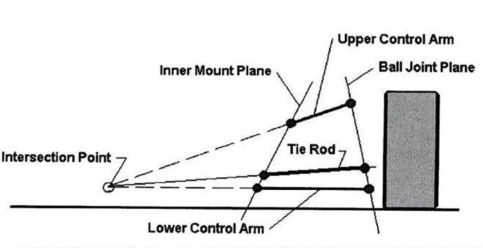
Instantaneouscenterofbothwishbonesandtierodmust besame.[2]
Tierodlengthissuchthat,itmustbeattachedtotheline ofintersectionofupperandlowerball joints.[2]
Thebelowfigureexplainsmoreaboutbumpsteergeometry.
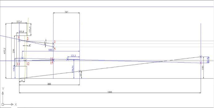
Soastoachievebumpsteerinourvehicle,steeringrackis place at 56 mm above floor. The following figure shows bumpsteergeometrydrawninAUTOCAD.Vehiclehassame instantaneousofbothwishbonesandsteeringrack.
5. DESIGN CALCULATIONS:
5.1 Steering System Design Calculations:
Assumptions:
Turningradius(R)=2300mm
Wheelbase(b)=1550mm
WheelTrack(t)=1200mm
VehicleWeight(W)=280Kg
TW=trackwidth
WB=wheelbase
R=radius
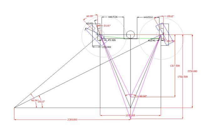
5.2 Ackerman geometry calculation: …….[3]
Value of the bump steer can be found from the below geometry.
AckermanAngle= ……….[3]
=42.32º
Steeringarmangle= ….[3] = =21.16º
Wheellocktolockrotation=θ+∅=42.35°+28.12°=70.47
%ofAckerman= = =100
5.3 Determination of Steering Ratio
ExistingSteeringratio = = …..[5]
ExistingSteeringratio=3.20
5.4 Determination of Steering Effort
Weightonfrontaxle=0.5×280=140kg
Weightoneachfrontwheel= kg=70 =686.6N
Friction force offers resistance to wheel rotations while negotiatingturn.
Frictionforce=μ×weightoneachfrontwheel=0.7×686.6= 480.7N
Torquerequiredatsteeringwheel=Frictionforce×radiusof pinion
Torquerequiredatsteeringwheel=480.7×20=9614N.mm
SteeringEffort= = =83.60N [3]
5.5 Calculation for M6 bolt:-
P=2kN–lateralforceontierod
Factorofsafety–2.5
Permissibletensilestrength=400N/mm²
σ= …….[1]
160= :d=3.98mm
5.6 Bending calculations for bolt: -
P=2000N
D=8mm
σb = …….[1] = =66.80N/mm^2
Doubleshearcalculations:
P=2000N
D=6mm
D= ……[1]
8= τ=21.21N/mm^2
Duringdoubleshearing,
τ=65.01N/mm^2
65>21.21N/mm^2:Designissafe.
5.7 Tie rod calculations:
θ= …..[1]
θ= =25.6kN/mm
τ(max)= 92.5=
Mb=25.8KN/mm
σb= …….[1]
σb=
σb= 131.3N/mm^2
Shearstress: τs= ……[1]
τs=
τs=65.1N/mm^2
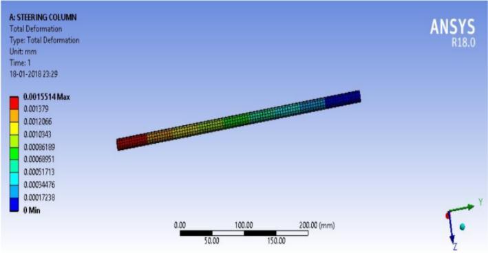
5.8 Steering Column Calculations:
RequiredData:
Lengthofcolumn(L)=200mm
Cfactor=di/d0=0.5
Permissibleangleoftwist=30
Diameterofsteeringwheel(D)=230mm
Modulusofrigidityofstainlesssteel=77200Mpa
Maximumtorqueonsteeringwheel(Mt) Forceonsteeringwheel(F)=83.6N
Mt=D*F=230*83.6
Mt=19228N-mm
Design of Hollow shaft on basis of Torsional Rigidity:
Θ=(584*Mt*L)/77200*d04(1-c4) …..[1]
3=(584*19228*200)/77200*d04 (1-0.54)
d0=12.09mmi.e.d0=14mm
Therefore di=7mm
Θ=(584*Mt*L)/77200*(14)4(1-0.54)
Θ=1.66840
Hence,FactorofSafety=3/1.66 =1.79
5.9
Ergonomics consideration for driver and as per the rule outerdimensionsofsteeringwheelsisdecided.
Fr =2000N
L10h=4000hrs.
N=750rpm
Bearinglife–
L10= ……..[1] =180millionrevolution
Dynamicloadcapacity–
P=Fr=2000N
C=P* …….[1]
=2000* =11292.43N
6.
5.10 Bearing calculations:
Fr =radialload
L10h=usedbearinglife
N=speedofrotation
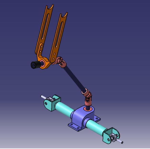
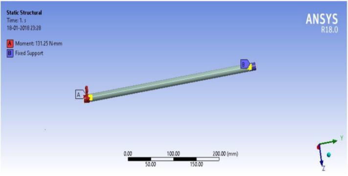
7. Analysis of components: -
7.1 Tie rod analysis:-
Tierodloading[6]
8.2
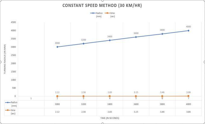
Hereturningradiusiskeptconstantandtimefordifferent speedtocompletethecircleiscalculated
-
Fortestingofsteeringsystem2methodsarefollowedand theyare:-
Constantspeedmethod.
Constantradiusmethods.
Time required in both the methods are calculated by stopwatchandtheresultsareplottedongraph.

Herespeedofthevehicleiskeptconstantat30km/hr.and time required to complete different turning radii are calculated.
While designing the vehicle the primary objective was to makethevehiclelight,compact,ergonomicandsafeforthe driver. While designing the system all the conditions of a racingenvironmentsuchasSpeedycornering,properturn and steering response were considered. Steering system functions desirably and the resulting vehicle is safe, attractive,reliable,economicalandfuntodrive
10.
Wewouldliketoexpressourspecialthanksofgratitudeto our team “Team Nequit” and “Automobile Engineering Department, RIT, Islampur” for guiding us throughout the process.
11. REFERENCES
[1] V B Bhandari, Design of Machine Elements, third edition,McGrawHillEducation,India,2010
[2] Thomas D. Gillespie, Fundamentals of vehicle dynamics, Society of Automotive Engineers, Inc. 400commonwealthdrive,Warrandale,PA150960001
[3] WilliamF.Milliken and DouglasL.Milliken,“Race Car Vehicle Dynamics”, Society of Automotive Engineers, Inc. 400 commonwealth drive, Warrandale,PA15096-0001
[4] Cristina Elena Popa, “Steering System and SuspensionDesignFor2005FormulaSAE-ARacer Car”, UniversityofSouthernQueensland,Facultyof EngineeringandSurveying,2005
[5] Caroll Smith, “Racing Chassis and Suspension Design”,societyofAutomotiveEngineers,Inc.400 commonwealth drive, Warrandale, PA 150960001,2004
[6] “Analysis and design of steering and suspension system by computer and mathematical methodology”AkashSood,AbhishekPandey,Savita Vyas,AvadeshK.Sharma,Internationaljournalof current engineering and scientific research (IJCESR), ISSN (PRINT): 2393-8374, (ONLINE): 2394-0697,VOLUME-3,ISSUE-1,2016
[7] RulebookFORMULABHARAT2019
12. Authors
Shreyash Satish Chougule TechnicalLead(TeamNequit) AutomobileEngineeringStudent, RIT,Islampur.


Jotiba Vinayak Avatade TeamCoordinator(TeamNequit) AutomobileEngineeringStudent, RIT,Islampur.