ANALYSIS OF POWER WIRE COMMUNICATION SYSTEM
Vaibhav V Rajguru1 , A.U Wagdarikar2
Abstract: The communication over power wire we can use for transferring data on low and medium speed. This communication allows to reduce wires used for sensor networks, signal wires and data transmission. It can use for vehicles having more number of sensing elements and number of BCM of featured vehicle. So sensors are connected with transmitter controller board via cable, Power wire transmitter will transmit sensor data over same power wire which provides power to sensor device, transmitter and receiver board. This communication will be the good solution for reducing number of wires for multiple sensor device interfacing. The major application area for this system would be electrical vehicle which have multiple sensor networks and complex wiring.
Keywords: BCM, Electrical vehicle, Sensors, Wiring, Power Wire communication
1. INTRODUCATION:
As a dependable alternative networking medium, this study offers communication on power wire system that allows in-vehicle communication for the transmission of control messages and sensor data from sensor location to receiver control module. The Power wire Communication can be sue for multiple sensor networking, sending short data massages and vehicle system uses an existing DC/AC power wires as the communication media, which doesn’t require an additional signal wires for sending data and signals in-vehicle signal transmission We can achieve the reduction of number of wiring harness from a system where large number of sensors and slave network works. For example, solar panels are located at far distance from control station in solar electricity generation system. Power Wire Communication will help to send data like solar panel position altitude, voltage and current measurement near to the solar panel terminals which is quite difficult with manually for every solar panel. Second exampleiswecanutilizethissystemforfeaturesofvehicle (Stoplight,reverselight,numberplatelight,demister,rear wiper, rear indicators) with the safety features like short circuit protection, fault protection and feedback to vehicle controlunit.
This power Wire communication will eliminate the number of wires, complexity of wiring harness design, weight of wire and production of wiring harness. Hence costwillcomedown
2: Author review
Analysis Review result of author 1:
Sheng-Xiu Lin, Yuan-Hua Zhang, Chao-Tang Yu, WeiWen Hu, Liang-Bi Chen, and Wan-Jung Chang – “A DC Power-Line Communication based In-Vehicle Safety Aided System for Rear Vehicles Road Safety” [3]
This paper proposes an in-vehicle safety aided system, whichadoptsDCpower-linecommunication(DCPLC)asa maintransmissionchannel.
Thesystemiscomposedwith
Voice-to-text(VTT)module
Twoembeddedcomputermodules
TwoDCPLCtransceivermodules
Textandvideomessagedisplaymodule
Distancemeasurementmodule.
Moreover, the proposed system is successfully installed and tested in a real vehicle. The experimental results showed that the proposed system can have a data of distance to the adjacent rear vehicle, and display front view video with alerting messages for drivers of rear vehicles.
Analysis Review result of author 2:
S. Barmada, M. Raugi, M. Tucci, T. Zheng - “Power Line Communication in a Full Electric Vehicle: Measurements, Modelling and Analysis”.[2]

The technological implementation is nowadays done by using different data bus (Local Interconnect Network, Controller Area Network, Media Oriented Systems Transport, FlexRay), depending on the required communicationspeedandreliability.
A modern vehicle of average dimension is characterized by a communication grid of several km, with a constantly increasing number of connectionpoints(morethan200nowadays).
The weight of the wiring harness is second only comparedtotheengine–gearboxweight.Itisnot
difficult to understand that the complexity of this structure will soon become an issue difficult to manage,alsofromthediagnosticandmaintenance pointofview.
Forthisreasontheuseofpowerlinestotransmit data could reduce this problem, since it would remove part of the cables (or all of them in the best case) for command and control with enormous advantages in terms of weight, space andcost.
3: SELF SYSTEM ANALYSIS (Author: Vaibhav
review
Block diagram analysis description
1. The UART transmitter and receiver for communicationwithtwomicrocontrollerssystem.
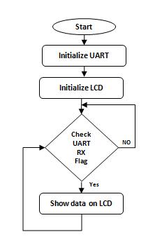
2. Interfacing resistive sensor (potentiometer) and two switches as input to the transmitter controller.
3. InterfacingLCDforshowingthetransmittingdata.
4. Interfacing filters at receiver with receiver microcontroller pin and interfacing LCD for showing received data from transmitter to show thecompletecommunicationoverpowerwire.
ANALYSIS OF SYSTEM FLOWCHART WORKING
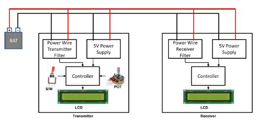
TransmitterFlowchart:
1. Microcontrollerwillinitializecommunicationport, GPIOportsandADCport.
2. Sensors like level sensor, switch type sensors ate initialized. Date read from sensors is shown on transmitter LCD display, simultaneously sent on powerwiremedia.
3. Checking for next data and reapete 1st and 2nd numberfunctioninpollingtechnique.
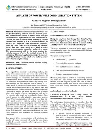
Receiverflowchart:
1. Initializecommunicationport.
2. Waitfordatareceiveinterrupt.
3. DisplaythedataonLCDdisplay.Repeat1st and2nd inpollingtechnique.
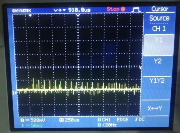
The received pulses form are so noisy and having distortions. So this received distorted signal pulses are filteredtogetremovedfromnoise.
Data pulses from communication port pin of transmitter controller. Amplitude is 5V that is
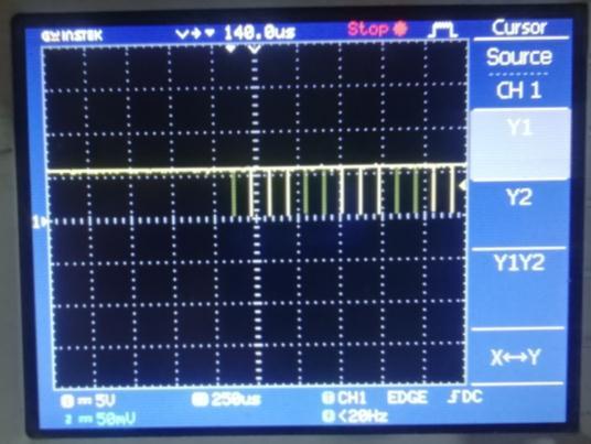
pulses
Thecommunicationsignal
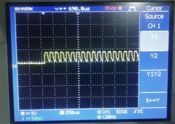
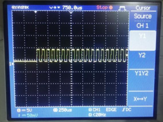
Afterfilteringandbufferstagewegetthepulseswhichcan readable for receiver microcontroller communication port anddecodethetransmitteddatatodisplayonLCD.
I have analyzed a 12V DC-based Power Wire Communication system for many applications who are working on DC power. in solar system and in-car communication,inordertomakeaalternativenetworking methodforsolarandvehicleinthisstudy.Themaingoalof thisworkforanapplicationistodo messagetransmission via an Power Wire Communication system It can provide the performance, data rate, dependability, flexibility, and cost-effectivenessrequiredformentionedapplications.
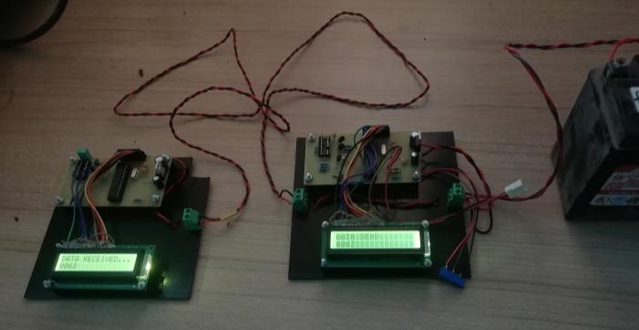
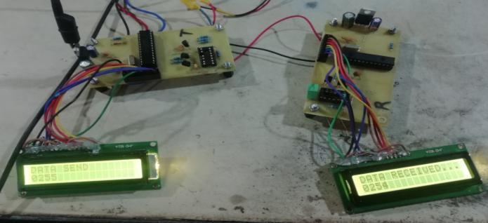
POWER WIRE COMMUNICATION PROJECT SETUP ANALYSIS:
[2]L.-B.Chen,H.-Y.Li,W.-J.Chang,J.-J.Tang,andK.S.-M.Li, "An intelligent vehicular telematics platform for vehicle driving,"inL.-B.Chen,H.-Y.Li,W.-J.Chang,J.-J.Tang,andK. S.-M. Li, "An intelligent vehicular telematics platform for vehicle driving," in An SDN-MQTT Based Communication SystemforBattlefieldUAVSwarms[J]
[3] Failure Inference for Shortening Traffic Detours[C]/ Proceedings of the International Symposium on Quality Service. XU A, BI J, ZHANG B. Failure Inference for Shortening Traffic Detours[C]/ Proceedings of the International SymposiumonQuality Service.1-10, Beijing, China,2016.
In project setup there is two PCBA boards, power line transmitter and power line receiver board. Both boards are interfaced with batter cables only. This battery power cable is responsible for communication between them. Transmitted ADC data count is shown over transmitter as wellreceiverdisplay.Thetoleranceofreceiveddatacount is±2counts.
[4] N. Taherinejad, R. Rosales, L. Lampe, and S. Mirabbasi, “Channelcharacterizationforpowerlinecommunicationin a hybrid electric vehicle,”in Proc. IEEE International Symposiums Power Line Communications and Its Applications(ISPLC),March2012,pp.328–333.
[5] Xiong F, Li A, Wang H, et al. IEEE Communication Magazine, vol. 57, no. 8, pp. 41-47, 2019.Optimal LinkDisjoint Node-"Somewhat Disjoint" Paths [2] YALLOUG J, ROTTENSTREICH O, BABARCZI P, et al.[C]/ IEEE International Conference on Network Protocols Proceedings.1–10,Singapore,2016.
[6] H J GENE, X G SHI, Z L WANG, et al. Efficient LFA implementation method[J]. Journal of Software, 29(12), 3904-3920, 2018. Full Protection Made Easy: The dispath IP Fast Reroute Scheme [J]. ANTONAKOPOULOS S, I3EJERANO Y, KOPPOL P. IEEE/ACM Transactions on Networking,vol.23,no.4,pp.1229-1242,2015.
[7] A Sudhakar, Shyammohan S Palli "Circuits and NetworksAnalysisandSynthesis,"FourthEdition
13.
TheadvantageofthePowerwirecommunicationistosend and receive data signal over DC power supply wire. Communication over power supply wire will allow to minimizethewirerequiretosendsensordata innetwork Reduction in number of wire will lead to minimize complexity, cost and weight of wiring harness in said applications and useful for automotive industries The advantage of power wire communication is can support sensor networks with minimum wire count for long distance(severalmeters)communication.
REFERENCES:
[1] R. P. Antonioli, M. Roff, Z. Sheng, J. Liu, and V. C.M. Leung, "A realtime MAC protocol for in-vehicle power line communications based on homeplug GP," IEEE 81st VehicularTechnologyConference(VTCSpring'15),pp.1-5, 2015.
[8] G.-N. Sung, C.-M. Huang, and C.-C. Wang, "A PLC transceiverdesignofin-vehiclepowerlineinflexray-based automotive communication systems," IEEE International Conference on Consumer Electronics (ICCE'12), pp. 309310,2012.
[9] M. Wilson, H. Ferrira, and R. Heymann, "Markov modelling of invehicle power line communication," AFRICON'13Proceedings,pp.1-6,2013.
[10] M. Bogdanovic, “Computer based simulation model realization of odfdm communication over power lines,” in Proc.TelecommunicationsForum(TELFOR),2012.