
Designing FSEV suspension system in Lotus Suspension Analysis SHARK
1,2,3,4Undergraduate Student, Department of Automobile Engineering, Saraswati College of Engineering, Kharghar, Navi-Mumbai, Maharashtra, India.
5Assoc. Professor, Department of Automobile Engineering, Saraswati College of Engineering, Kharghar, Navi-Mumbai, Maharashtra, India. ***

Abstract - In this study, the suspension geometry of a Formula style race car's suspension system was designed accordance with a Kawasaki Ninja 650® and later the engine was optimized to KTM Duke 390® for low-end torque from mid-range power delivery of Kawasaki Ninja 650® engine. In this study the suspension system is kinematically simulated with Lotus Suspension Analysis SHARK® Software. These systems are subjected to several forces in both dynamic and static conditions. Lotus Suspension Analysis SHARK® gave us an idea about the load-cases applied on the vehicle. Our primary goal is to increase suspension stiffness, which will ultimately reduce spring travel. A major change in stiffness willbemadeat therearsuspensionsystemduetoasignificant weight changebroughtthroughthereplacementoftheengine, and perhaps a subsequent change in the static load on both axels of the vehicle, requiring a revised version of the front suspension geometry. Bump steer is to be improved dynamically over prior vehicles, and body roll is to be controlled substantially.
Key Words: Suspension, suspension arms, suspension actuation mechanisms, Bump steer, Understeer, Vehicle Roll, Lotus Suspension Analysis SHARK.
1. INTRODUCTION
Thedesignanalysisandoptimizationofsuspensionwillbe demonstratedinthisstudy.Developmentandredesignofthe suspension system for a formula type racing vehicle that providesacceptabledrivecomfort,goodstability,andgreat manoeuvrabilityisthegoalofthisproject.TheSuspension systemisadevicethatconnectsthebodywiththewheels.In boththestaticanddynamicstates,thereareseveralforces operatingonthewheels.Alloftheseforceshaveanimpact onthedesignoftheSuspensionAssembly.Theprojectaimed touncoveranyproblemswiththeoldvehicleandthenuse thesefindings,coupledwithappropriateresearch,tocreate a new suspension system that possesses improved performance.Completionoftheprojecthasseenthedesign ofgeometryforthesuspensionarms,suspensionactuation mechanisms,uprights.So,theprojectwillbeusedforanew vehiclewhichwillbebuiltaccordingtotheengine KTMDuke
390® whicheventuallyneedsanewsetupofsuspension& steering
2. METHODOLOGY
Tooptimizebumpsteerandrollvalues,itwasnecessaryto examinethesuspensiongeometryusingspecializedsoftware Lotus Suspension Analysis SHARK® waschosenforitsuserfriendly features and then analyzing them. Designing the suspension kinematics for an FSAE vehicle is a critical processthatcansignificantlyimpacttheperformanceofthe vehicleonthetrack.Inthisstudy,wewilldiscussthesteps involvedindesigningthesuspensionkinematicsforanFSAE vehicle with pull-rod suspension at the front and pushrod suspension at the rear, using Lotus Suspension Analysis SHARK® .

Tire and Suspension Selection:


As we select Rims which have 6-inch width, we would requirenewtirestoaccommodatethewidthofthewheels. WehaveselectedHoosierTiresofsize(18x6R10).Upuntil the end of 2015, our team had been using a pushrod suspension at the front and a push rod suspension at the rear for many years We have been inspired by the suspensiongeometryofFerrariSF15-Tandrecentlywehave upgradedoursuspensionsystemintoapullrodsuspension atthefrontforlowerCGandclosetorollCentre.

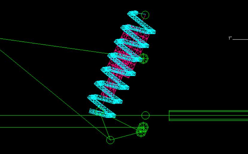
In the new edition Fig -6, spring travel is less than it was, indicatingthatthesuspensionsystemisstifferthanitwas. Thiswasattainedbyredesigningthesuspensiongeometry. Rolloverstabilitywasultimatelyimprovedbyreducingthe suspension's overall position Fig -8, which also helped to decreasetheCGheightandbringitclosertotherollcenter. Inthenewervehicle,thepushrodisconnectedtothelower controlarm(LCA) Fig -8,whichimprovesmotionratioand lowersthebellcrankpivotpoint,ascomparedwiththeold vehicle,wherethepushrodisconnectedtotheuppercontrol arm(UCA) Fig -7.


In Fig -9, The bump steer is a condition where the toe-in angleincreasesasthewheeltravelsverticallyandiscaused by the inner tie rod end not being aligned with the inner mount plane. This condition was set specifically for the driver'sneeds.Thecargraduallyundersteersasthetoe-in rises.
In Fig -10,Accordingtoourdrivers'needs,thecarshould havemorebrakingandthrottlecontrol,whichwillgivemore roomforadjustments.
Hence,whatwehaveaccomplishedistohaveslightlymore understeer in the car, which will boost the driver's confidence while cornering, and it was achieved with a slightlyincreasedamountofbumpsteer.
5. CONCLUSIONS
In this study, we have replaced the engine which brought significantchangeinweight.Keepingthatinmind,wehave optimisedoursuspensionsystemintoapull-rodandpushrodgeometrywhichhelpedinachievingincreasedrollover stability,bumpsteerwhichisincreasedby170%,alongwith the understeer behavior with vehicle performance parametersappropriateforthedrivingstyleofourdriver.
REFERENCES
[1] AlejandroDiaz,OsvaldoFernandez,RicardoGonzalez, Christian Ramos. "FSAE 2015 Chassis and Suspension FinalReport",EML4905SeniorDesignProject 2014
[2] SamantSaurabhY.,SantoshKumar,KaushalKamalJain, Sudhanshu Kumar Behera, Dhiraj Gandhi, Sivapuram Raghavendra, Karuna Kalita. "Design of Suspension System for Formula Student Race Car". 12th InternationalConferenceonVibrationProblems,ICOVP 2015,ProcediaEngineering144(2016)1138–1149
[3] JockAllenFarrington."RedesignofanFSAERaceCar’s Steering and Suspension System". University of Southern Queensland Faculty of Engineering and surveying. Courses ENG4111 and ENG4112 Research Project.2011
[4] Ayush Arvind Singh, Puneet Sai Naru, Kishor Laxman Adsare, Mr. Shrikant Baste. "WHEEL ASSEMBLY AND SUSPENSION CORRELATION OF FORMULA STYLE VEHICLE". International Research Journal of ModernizationinEngineeringTechnologyandScience, Volume:04/Issue:05/May-2022, e-ISSN: 2582-5208. 2022
[5] Ojas Babannavar, Aditya M Deshpande" Design, analysis,andoptimizationofanFSAEupright".IOPConf. Series: Materials Science and Engineering, doi:10.1088/1757-899X/1166/1/012043.2021.
[6] MuhammadIzzatNorMa'arof,VongRatanakvisal,Lim Jin Wei, Amir R. Ghani, Girma T. Chala. “Design and Analysis of the Suspension Upright Structure of a Formula SAE Car”. International Conference on Innovation and Technopreneurship, Vol.2019:019, eISSN:2600-7920.2019.
[7] Jixiong Li, Jianliang Tan, Jianbin Dong. “Lightweight DesignofFrontSuspensionUprightofElectricFormula Car Based on Topology Optimization Method”. World Electric Vehicle Journal, doi:10.3390/wevj11010015. 2020