
POWER GENERATION BASED ON WASTE HEAT RECOVERY
 Mandadi V L N S Karthikeya Sharma1
PG student, Department of Mechanical Engineering1 , Annamacharya Institute of Technology & Sciences, Kadapa, India1 ***
Abstract - Production of electricity from low or moderate temperatures is very difficult. To make it possible we need modern techniques. In every industry, power plants and process plants lot of low grade energy is wasted into the atmosphere. To recover this low grade energy, we propose Kalina cycle as a modern tool of thermodynamics. This Kalina cycle consists of multi component fluids as thermodynamic working fluid. Most of the heat is wasted near the boiler of the steam power plant, or at the flue gases coming out from chimney or stack. Using Kalina cycle we perform heat recovery task quite easily. Kalina cycle uses Ammonia and Water as working fluid. Using Aspen plus simulation tool the simulation work was performed and a reliable result was obtained. The Heat recovery from flue gases coming out from chimney of any industry may be studied using Aspen plus. Composition of Ammonia and Water mixture was varied from 0.5 to 0.9 mass fraction of Ammonia. Flow rate of hot gases is kept constant, assuming that there is constant burning of fuel in the boiler. Power generated in this process was tabulated and efficiency of the process is also calculated.
Key Words: KalinaCycle,Fluegas,HeatRecovery,Power
1. INTRODUCTION
The energy demand in the world is expected to increase continuously. In order to minimize the negative environmental impact from utilizing energy resources, more efficientenergyconversionprocessesarenecessary. The electrical power demand is also expected to be very highinfuture.Itisthereforeagreatinteresttobetakento improvetheefficiencyof powergeneratingprocesses and power plants. This can also be very good from for the national economicpointof view. Therearemanypossible ways in which these improvements can be achieved [4]. KalinacyclewasfirstdevelopedbyAlexandrI.Kalina[1]in the late 1970’s and early 1980’s. Based on this, several Kalinacyclehavebeenproposedfordifferentapplications. Kalinacycleusesaworkingfluidcomprisedofatleasttwo differentcomponents, typically Water and Ammonia. The ratio between those components variesin different section or parts ofsystem to decrease thermodynamic irreversibility and thereby to increase the overall thermodynamic efficiency [1] In thermodynamics, the Carnotcyclehasbeendescribedasbeingthemostefficient thermalcyclepossible,whereintherearenoheatlosses,and consistingof four reversible processes, two isothermal
andtwo adiabaticprocesses. ButInaCarnotengineheat additionandrejectionhappenatuniformtemperature.

1.1 Ammonia-water power cycle principle
Theammoniaandwatermixtureisnon-azeotropic.The characteristic for non-azeotropic mixtures is that the compositionandtemperaturechangesduringboilingatall possiblecompositions of the mixture. When the mixture starts boiling, a separation of the components takes place. The vapour is richer in ammonia fraction than the liquid. The starting point for the boiling is called the bubble point and the end point is called the dew point. The bubble point temperature for a mixture with a mass fractionofammoniaof0.5atapressureof11MPais204°C. During the boiling the temperature of the mixture increasesasthecompositionchanges.Whenthetemperature oftheboilingmixturehasreached 230°C, the mass fraction of ammonia in the liquid phase is 0.37, while in vapour phaseitis0.70.
1.2 Comparison between Kalina cycle, Rankine cycle and ORC
TheKalinacycleisprincipallya‘‘modified’’Rankinecycle. These special designs, either applied individually or integratedtogetherinanumberofdifferentcombinations, compriseafamilyofuniqueKalinacyclesystem.Intheory, theKalinacyclecanhelptoconvertapproximately45%of direct-firedsystem’sheatinputtoelectricityandupto52% foracombined-cycleplant.Moreover,Kalinacyclecangive up to 32% more power in the industrial waste heat applicationcomparedtoaconventionalRankinesteamcycle. However, the Kalina cycle in small direct-fired biomass fuelledcogenerationplantdonotshowbetterperformance
thanaconventionalRankinesteamcycle.Whenbothcycle areusedtogetherinasamepowergenerationsystemwith samethermalboundaryconditions, it can befoundthat when the heat source is 1100 :F (537:C), Kalina cycle shows 10-20%highersecondlawefficiencythanthesimple Rankinecycle[14].
2. Literature Review
A.Kalina,H.Leibowitz[1],aimsataverylargeincreaseofthe efficiencywhilekeepingcostsbasicallyatthesamelevelof other applications. Author suggested that, for the better performanceofthecycleammoniamassfractioninthecycle variesfrom0.7to0.9withmassflowrateof25kg/s,andinlet pressuretotheturbineshouldbebetween25barto40bar withoutletpressuretotheturbineas7-10bar.Itshouldalso be mentioned that the use of a water ammonia mixture allowsthetotalflowofthefluidtoremainwithinreasonable limits.
Carlos Eymel Campos Rodríguez .et.al [3] deals with the thermodynamic analysis, of first and second law of thermodynamic of two different technologies, (ORC and Kalina cycle) for power production through an enhanced geothermal system (EGS). In order to determine the performanceofboththermalcycles,heevaluated15different working fluids for ORC and three different composition of ammonia-water mixture for the Kalina cycle. For this purpose,theAspen-HYSYSsoftwareisusedbytheauthorto simulate both thermal cycles and they calculated thermodynamic properties of organic and ammonia-water solution based on Penge-Robinson Stryjeke-Vera (PRSV) EquationofState(EoS).
IsamH.Aljundi[6]studied,theenergyandExergyanalysisof Al-Hussein powerplantinJordan.Hisprimaryobjectives wastoanalysethesystem componentsseparatelyandto identify and quantify the sites having largest energy and Exergy losses. In addition, the effect of variation of environmental conditions, on this analysis will also be represented. Theperformanceoftheplantisestimatedbya componentwisemodelingandadetailedstudyofenergyand Exergylossesfortheconsideredplanthasbeenpresented.
JiangfengWanget.al[7]studiedthesolar-drivenKalinacycle toutilizesolarenergyeffectivelyusingammonia-water,due toitsvariedtemperaturevaporizingcharacteristic.Inorder toensureacontinuousandstableoperationforthesystem,a thermalstoragesystemisintroducedtostorethecollected solarenergyandprovidestablepowerwhensolarradiation isinsufficient.Amathematicalmodelwasdevelopedforthe simulationofthesolar-drivenKalinacycleundersteady-state conditions and also a modified system efficiency were definedtoevaluatethesystemperformanceoveraperiodof time. He found the results that indicate, there exists an optimal turbine inlet pressure under given conditions to
maximize the net power output and the modified system efficiency.Theoptimizedmodifiedsystemefficiencyis8.54% underthegivenconditions.TheKalinacycle,whichutilizes ammonia-waterasitsworkingfluid,wasoriginallyproposed byAlexanderKalinain1983.
Mark D. Mirolli [10], suggested that, cement production consumes large quantity of heat, for kiln, calcination and drying process. Also lot of energy is consumed by the electrical motors for grinding, fans, conveyers and other motor driven processes. By assembling the Kalina cycle whichutilizesthewasteheatfromthevariouspartsofthe cement production process, it is possible to generate electricitywithoutconsumingfuel.Thisreducesthecostof cementproduction.Authornoticedthat,thermalefficiency usingKalinacycleimproves20-40%,incomparisonwiththe conventionalhotgaspowerplant.Kalinacyclepowerplantis moreenvironmentfriendlythananyotherpowergeneration plant because of utilization of ammonia-water as working fluid.
Omendra kumar singh, S.C. kaushik [11], did a computer simulationofaKalinacyclecoupledwithacoalfiredsteam power plant with the aim of examining the possibility of exploiting low-temperature heat of exhaust gases for conversion into electricity. They described the numerical model, to find the optimum operating conditions for the Kalinacycle.Theeffectofkeyparametersnamelyammonia mass fraction in the mixture and ammonia turbine inlet pressureonthe cycleperformancehasbeeninvestigated. Resultsindicatethat,foragiventurbineinletpressure,there is an optimum value of ammonia fraction that yields the maximumcycleefficiency.
3. PROCESS DESCRIPTION AND SIMULATION
3.1 Simulation of Kalina cycle using Aspen plus
In industry complicated problems are often not solved by hand for two reasons: human error and time constraints. There are many different simulation programs used in industry depending on the field, application and desired simulationproducts.Whenusedtoitsfullcapabilities,Aspen can be a very powerful tool for a Chemical Engineer in a varietyoffieldsincluding oil andgasproduction,refining, chemical processing, environmental studies and power generationetc.Kalinacyclecanalsobesimulatedthrough Aspenplus.AsweallknowthatAspenprovidesaveryhandy toolsforsimulation.Aspenconsideredalltherealandideal methodinthepropertytabwhichprovidesareliableresult ofsimulation.Thisresultmaybetreatedasaresultfoundby direct experiment in the laboratory. Flow sheet of Kalina cycle is drown in the Aspen plus using the equipment availablewithAspenplus.Noequipmententryistakenfrom outsideofAspenforthesimulationpurpose.
3.2 Beginning of simulation
Step-1,Aspenprogramstartedinthecomputerbyclicking ontheAspenplususerinterface.
Step-2,whattypeofsimulationisto beperformed,that is chosenfromthesimulationmenu.Formypurpose,general simulationwithEnglishunitischosen.Thereare26different optionsofsimulationwithAspenplusisavailable.

Step-3,byclickingonOKbutton,Aspenredirecttoanother page.Onthispagewecancreateourflowsheetasperour requirement.
3.2 The process flow sheet
Apieceofequipmentisselectedfromtheequipmentmodel librarybyclickingonceontheflowsheetwindow,wecan placethisequipmentwhereitisrequired.Byfollowingthe sameprocedureforeachpieceofequipment,wecanaddas manynumbersofequipment’saswerequire.Afterplacing the equipment’s at it proper place, equipment’s are connectedwiththesuitablematerialstream.Aspenshasa feature that indicates the required stream and optional streamfortheequipment’s.Aspenalsohasfeaturetorotate, resize,andrenametheequipment’sandstreams.
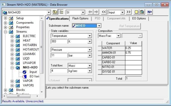
3.3 Data Input
AllofthedatainputforAspenisenteredintheDataBrowser window. This window can be opened by clicking on the eyeglassiconorbygoingtoData/DataBrowserintheMenu Bar. Aspen has two features in the Data Browser window thatcanbothhelpandhurttheuser.Thefirstofthesecanbe seen on the right hand side. Aspen highlights the areas where the input has been completed and has not been completedwiththeuseofeitherabluecheckmarkorahalf filledredcircle.However,itisnotalwaysnecessarythatall the required input are entered, especially if we are simulatingamorecomplexproblem.Thisfeaturewillonly tracktheminimaldatainputrequiredtorunasimulation.If onerequireddataisentered,byclickingtheblueNbuttonto gotothenextrequiredinputs.Whenalltherequiredinputs arecompleted,intherightmostbottomsitisindicatedby “Requiredinputscompletes”.
3.4 The process flow sheet Description
Hotexhaustgasescomingoutfromtheindustryispassed through a heat exchanger in order to exchange heat with ammonia-watermixtureflowinginthesameheatexchanger intheshellside.Hotfluegasesareflowinginthetubeside. Becausethevapourholdupofshellsideismuchhigherthan thetubeside.That’swhyammonia-watermixtureisallowed topassthroughshellside.Iftheliquidflowsinthetubeside, thepossiblevapourgenerationwillcreatedifficultyinflow. Afterheatexchangeammonia-water,liquid-vapourmixture passes through a separator, where vapour and liquid get separatedintotheirrespectivestreams(vapourandliquid stream).Fromthetopoftheseparatorvapourcomesoutas topstreamandbottomreleases liquid which is a lean
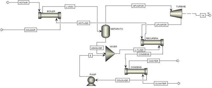
ammonia-water mixture. Top stream or vapour stream whichishighpressureandhightemperaturevapour,isfeed intotheturbine, whereitsenthalpyisutilisedtogenerate electricity.
4. RESULT AND GRAPHS
Whenallthedataareenteredintothecorrespondingdata space in the Aspen plus. The software indicates all the required input is complete. That means we can run our simulation by clicking the N button. After completion of calculation,thesoftwareindicatesthecompletionofgiven processthroughindicationofresults.Resultcorresponding tothestreamandblockcanbeobtainedbyclickingtheon streamorblock.
[2] BombardaP.,InvernizziC.M..,PietraC.,Heatrecovery from Diesel engines: A thermodynamic comparison betweenKalina and ORC cycles. Appliedthermal engineering.30(2010),pp.1-50.
[3] CarlosE.C.R,JoséC.E.P,OsvaldoJ.V,ElectoE.S.L. , VladimirM.C.,Daniel
[4] M.D , Fábio R. Lofrano D. , Vernei.G., Exergetic and economiccomparison ofORCandKalinacycleforlow temperature enhanced geothermal system in Brazil. Appliedthermalengineering.52(2013)pp.109-119.
[5] HoustonT.,ExergyI.,AlexanderI.KNovelpowercycle for combined-cycle system and utility power plants. Proceeding from the Eighth Annual Industrial Energy technologyconferences.(1986):pp.17-19.
[6] IsamH.A.,EnergyandExergyanalysisofasteampower plantinJordan.Appliedthermalengineering,Volume29 (2009),pp.324–328.
[7] JiangfengW.,ZhequanY.EnminZ.,YipingD.Parametric analysis and optimization of a Kalina cycle driven by solarenergy.Appliedthermal engineering,50(2013), pp.408–415.
[8] Jonsson,M.,Yan,J.,Ammonia–waterbottomingcycles:a comparisonbetweengasenginesandgasdieselengines asprimemovers.Energy,(2001):pp.31-44.
5. CONCLUSIONS
Based on the data input from a power plant as reported earlierusingaKalinacycleforwasteheatrecoveryatlow temperatureconditionusingAmmonia-Watersystem.Itis concludedthattheprocessgeneratessubstantialamountof energy for improving the thermal efficiency of the given power plant. Aspen was said to be a very powerful tool (software)tosimulatetheresultandarriveatasatisfactory result. It is also suggested that, the process can also be extendedtootherenergyintensiveindustrieslikecement, steel and glass etc. To find an economical solution to the excessivepowerconsumptionthroughapplicationofKalina cyclebywayrecoveringenergyfromwastestream.
REFERENCES
[1] A. Kalina., Leibowitz H., Lazzeri L., Diotti F. Recent development in the application of Kalina cycle for geothermal plant. Exergy inc., Hayward, cal., USA. AnsaldoEnergia,ViaN.Lorenzi8,16152,Genoa,Italy
[9] Lu X.L., Watson A., Deans J., Analysis of the thermodynamicperformanceofKalinaCycleSystem11 (KCS11)forgeothermalpower plant-comparison with Kawerau Ormat binary plant. Proc. ASME 3rd InternationalConferenceonEnergySustainability,San Francisco,California,USA,No.90165(2009),pp.19-23.
[10] MarkD.Mirolli,TheKalinacycleforcementkilnwaste heat recovery power plants. Conference paper. (2005).pp.330-336.
[11] OmendraK.S.,S.C.K.,Energyandexergyanalysisand optimization of Kalina cycle coupled with a coal fired steam power plant. Applied thermal engineering, 51 (2013)pp.787-800.
[12] TribusM.,TheKalinaPowerCycles,Aprogressreport, 1989.
[13] Valdimarsson, P., ORC and Kalina Analysis and Experience,2003.
[14] XinxinZ.,MaogangH.,YingZ.,Areviewofresearchon theKalinacycle.
[15] RenewableandSustainableEnergyReviews.16(2012) pp.5309–5318.
[16] Matthew B., René O., Aspen plus 12.1 instructional tutorials. University of Washington department of chemicalengineering.
[17] Aspenpropertyuserguideversion10.2
[18] RalphSchefflan,Hoboken,Teachyourselfthebasicsof Aspen plus, New Jersey, A John Wiley & sons, inc., publication.
[19] http://kalinacycle.net“whatisKalinacycle”.
[20] http://www.learnengineering.org/2013/01/kalinacycle-power-plant.html