
Strength Improvement of Bus Body Structure with Design Modification


1Assistant Professor of Mechanical Department, Dr. A. D. Shinde Collage of Engineering, Gadhinglaj-416502, Maharashtra, India

2,3,4,5,6 Student of Mechanical Department, Dr. A. D. Shinde Collage of Engineering, Gadhinglaj-416502, Maharashtra, India ***
Abstract - In our society mobility conditions are adding drastically with growing population and contemporaneously environmental perceptivity is also adding. Thus it's making a big challenge for transport pots of government and private drivers to manage vehicles and business policy makers to handle them. Accordingly, the light and heavy passenger vehiclemanufacturers as well as vehiclebodybuilders haveto borrow new request conditions along with minimal introductory safety of the passenger.
The design includes detailed design, development and analysis of the body structure of machine. According to AIS law, performance parameters have to be followed by the machine body builders to insure needed strength. To insure strength of the machine body, all the machine body builders have to assay their design in any one of the FEA( Finite Element Analysis) tool. With the help of FEA tool bone can gain accurate results of strength of design in lower time. As notified in Rule number 126 of the CMVR 1989, all machine body builders have to use anyone of the FEA tools by themselves or with authorised test agencies to corroborate the strength.
Key Words: Bus Body Structure, FEA, Strength Improvement, Vehicle Body Builders
1. INTRODUCTION
AlltheOEvehiclemanufacturesellstheirvehiclesin driveawaychassisforms,sothatcustomercangetvehicle bodybuildingsdonasperhisrequirementsandchoicewith localbodybuilderswithlowcost.Theselocalbodybuilders use low quality parts and materials in a poorly designed bodywhichleadstoaccidentsometimelater.These body structures are not safe since designs are not optimal, for example these designs provide more heat transfer, noise, andvibrationsinsidethecabin.
All the automobile body builders have a big demand for compact body and can accommodate more number of passengerswithgoodsafetyofallthepassengers.Therefore these new body designs must have high strength to withstandmoreloadofincreasingpassengers.Thestrength ofbodyisanalysedandverifiedthroughtheFiniteElement
Analysis(FEA)softwareandlifesecurityoftheuserscanbe guaranteed.
1.1 Problem Description
In MSRTC workshop nearly 2000 number of bus are manufacturedper year. Theperiodic conditioning of these buseswillbedoneaftereverythreeyearsorafterrunning every three lack kilometres. In most of the cases it was observedthatfailureoccursatjointsatclitsorpillars,aswe canseeinfigure1&2.Sotherewillberequirementforthe replacement of the failed members to recondition. This replacement of components is very time consuming and tedious job. These buses aredesigned tosurviveat leasta minimum of ten lack kilometres. Therefore high strength designs,materialsandcomponentsmustbeused.
1.2 Objectives of the project
Demand for public transport is increasing day by day.Toensurestrengthofthenewlyinnovativelydesigned component,ithastobetestedandanalysed.Thesearethe objectivesoftheproject
1. Tocarryoutthedetailedthestudyofthestructure ofbusbodyasperAIS052standard.
2. Tostudyallthebusbodystructuretheory.
3. Failuremodesarestudiedandcause-effectdiagram isprepared.
4. ToprepareCause-effectdiagram.Todothestudyof failure modes by components structural analysis andtofindcriticalregionforfailureusingsuitable analysissoftware.
5. Toprovidesolutiontoavoidfailureofstructureof bus.
6. To carry out analysis of modified structure using analysissoftware.
7. To validate the simulation results of modified structureofbusbodybycomparingtheresultswith simulationresultsofexistingstructureofbusbody.
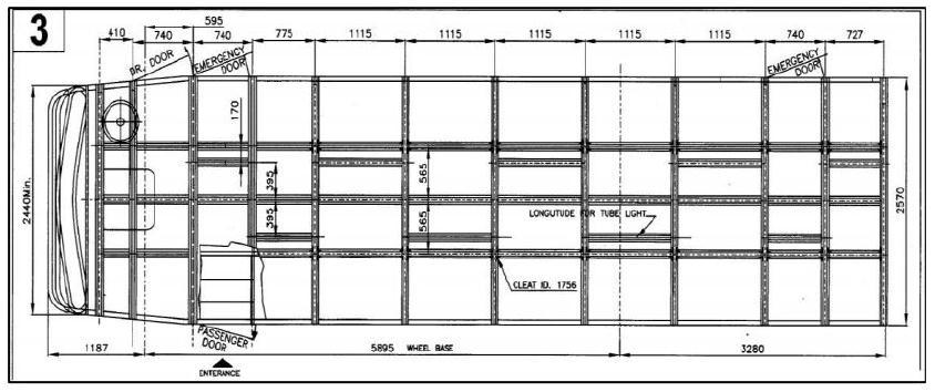
2. Dimensional specifications for a bus body
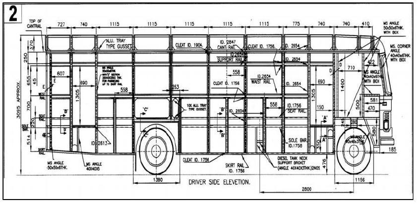
SpecificationsusedinMSRTC-2x2parivartanbusareas follows.BelowfigureshowsthedimensionsusedinMSRTC2x2parivartanbuswiththestandardsgiveninAIS_052
frameworkisdonebyusingM8boltswithrivetedjoints.Fig showstheassemblyofbusbodyaccordingtodimensions.
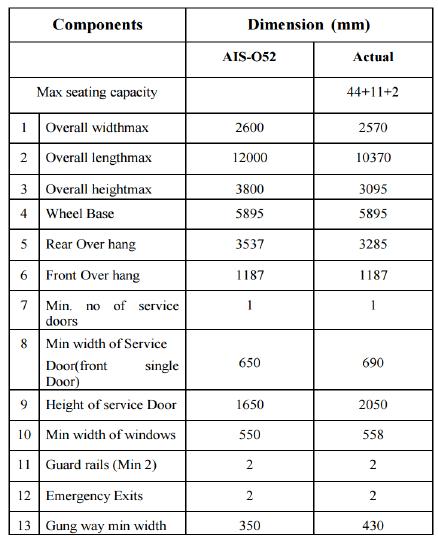
3. Layout of Framework of a bus body
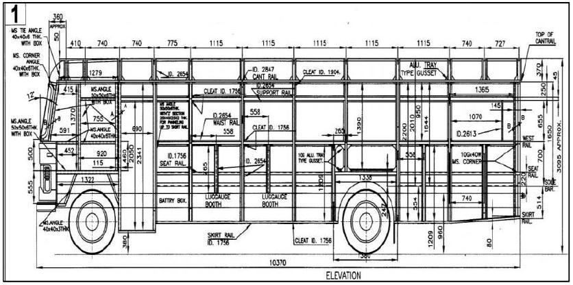
Layout of a bus body is shown in the below figure with dimensions. Material used for body is aluminium. The
4.1 Static Analysis
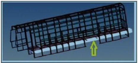
Boundary conditions are used to restrict the body with constraints and different types of loads. In this problem bottomstructureisattachedtothechassisofthevehiclethat isthelongmembersofthebottomstructuresareconnected. Therefore the long members of the bottom frame are constrainedwithalldegreesoffreedom.Alsotheloadof5Kg
inXdirection,5KginYdirectionand10KginZdirectionis applied.Theloadsappliedcanbeseeninfigure
Thereforetheforcesactingare
Xdirection=5x9810=49050N
Ydirection=5x9810=49050N
Zdirection=10x9810=98100N
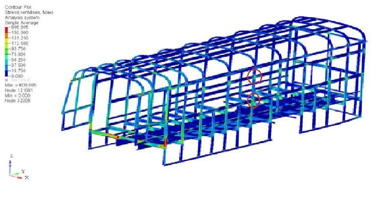
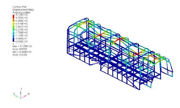
Stressesactingonthebodystructurecanbeseenincounter plot. The result shows the stress distribution in the body structurewhichcanbeseeninfigure6.3.Inthefigureitcan bealsoseenthatthestressconcentrationismoreattheclits. Thisisthepartwhichispronetofailureandwhichcanfailat theearliestduringaccidents.
Itcanbeseeninfigure6.4thatthisisthecriticalareawhich will fail on repeated loads and timely maintenance is required. Therefore this part of the structure needs to be modifiedandstrengthenedtoimprovethelifeofthebody structure.
4.2 Dynamic Analysis
Dynamictypeofanalysisisdividedintodifferenttypes, theyareasfollows
1.Modal
2.Frequency/response
3.Transient/response
4.Random/vibration
4.2.1 Modal Analysis
4.1.1
This analysis is carried out to find the systems natural frequency.
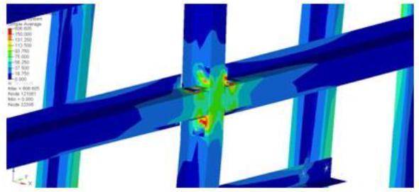
Table No. 2 NaturalFrequency

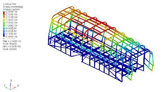
4.2.2 Frequency/response type analysis
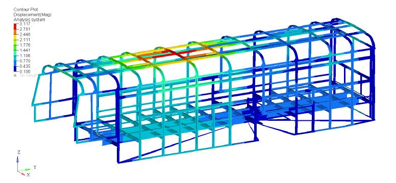
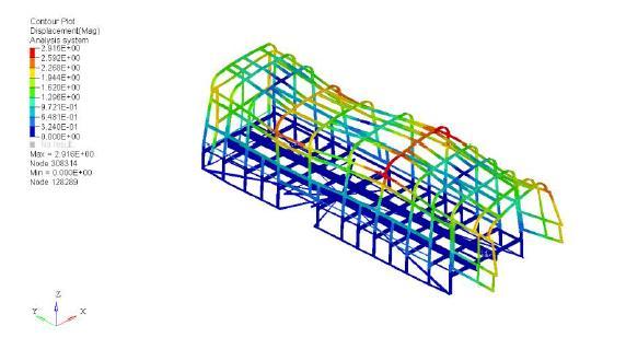
Thefiguresbelowshowtheresultforfrequency/response type of analysis. Figure 6.13 shows value of maximum/displacementof3.117m.Figure6.14showsthe result for equivalent type of stress. It was observed that maximumstresswas63.244MPaandthemaximum/stress atclitswas49.447MPa.

5. Modification Required for Clit

Duetotheproblemfacedbythepresentdesign,theclitwas requireda newdesigntoimprovethestrength.Therefore clitwasredesignedwiththedimensions76.2x50.8x6mm. Materialselectedissameasthatofpreviousclit.Figure7.2 showsthenewdesignoftheclit.
IntheprojecttheMSRTCbusbodystructurewasdesigned and analysed because some parts were giving lot of maintenanceissues.Thisproblemwassolvedbyredesigning theclitpartofthebusbody.Botholdandnewdesignswere analysedandcompared.Thebelowtablenumber8.1shows thecomparisonofnewandolddesignanalysis.
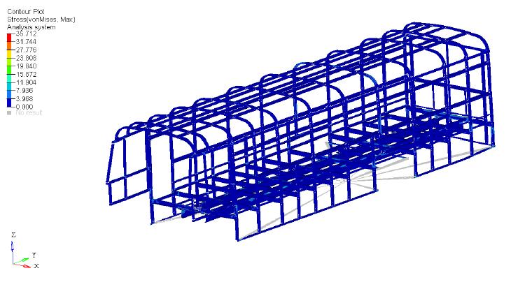
5.1 Analysis results
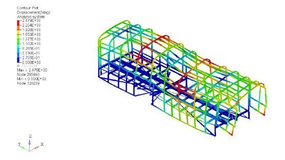
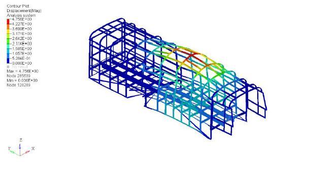
AfterredesigningtheclitintheCADsoftware,theclitwas replaced with the new model and again meshed and analysedforalltheconditionedwhichwasfollowedearlier. Forfrequency/responseanalysisitwasfoundthatmaximum displacementwas1.603m(figure6.3)andmaximumstress of35.71MPa(figure).
By seeing above table we can understand that with the modified design the structure of bus body can withstand moreloadandlastslonger.


ACKNOWLEDGEMENT
It gives us an immense pleasure to write an acknowledgementtothisPaper,acontributionofallpeople whohelpedusrealizeit.Wetakethisopportunitytoexpress ourrespectfulregardstoourbeloved Principal Prof. K. S.
Joshi formotivateustopublishthispaper.Alsoweexpress ourdeepsenseofgratitudeandappreciationtoourbeloved Project Guide Prof. Praveen Kokitakar for this enthusiastic inspiration and amicable in all phases of our Paper.
REFERENCES
A. Magnus G.H. Cruz, AlexandreViecelli, "A methodologyforreplacementofconventionalsteel by micro alloyed steel in bus tubular structures", MaterialsandDesign29,Elsevier,pp.539-545,2008.
B. J. Karliński, M. Ptak, P. Działak, E. Rusiński, "Strengthanalysisofbussuperstructureaccording toRegulationNo.66ofUN/ECE",Archivesofcivil andMechanical Engineering 14,Elsevier,pp.342–353,2014.
C. A.Gauchía,E.Olmeda,M.J.L.Boada,B.L.Boadaand V. Díaz, "Methodology for bus structure torsion stiffnessandnaturalvibrationfrequencyprediction based on a dimensional analysis approach", International Journal of Automotive Technology, Vol.15,No.3,pp.451−461,2014.
D. G. Zhang, X. Zhang, and B. Liu, "The Study of Bus Superstructure Strength Based on Rollover Test UsingBodySections",AdvancesinMSECVol.2,AISC 129,Springer,pp.315–322,2011.
E. H.S.Kim,Y.S.Hwang,H.S.Yoon,"DynamicStress AnalysisofaBusSystems",AnnualHyundaiMotor CompanyConference,Korea,2009.
F. SachinThorat,G.AmbaPrasadRao,"Computational analysis of intercity bus Withimproved aesthetics and aerodynamic performanceonIndian roads", International Journal of Advanced Engineering Technology,E-ISSN,pp.0976-3945,2011.
G. S.Butdee,F.Vignat,"TRIZmethodforlightweight bus bodystructure design",Achievements in Material and Manufacturing Engineering, Vol 31, Issue2,2008.
H. Prasannapriya. Chinta ,Dr.L.V.VenugopalRao, "A New Design and Analysis of Bus Body Structure", IOSRJournalofMechanicalandCivilEngineering,eISSN: 2278-1684,p-ISSN: 2320-334X, Volume 11, Issue5VolI,pp39-47,2014.
I. Automotive Industry Standard-052, “Code of PracticeforBusBodyDesignandApproval”IS7331983 “Specification for wrought Aluminum and Aluminumalloybars,rodsandSections”
J. NitinGokhale,“PracticalFiniteElementAnalysis”, 2007