
Design and Analysis of an 8-Speed Gear box.
Abhishek Chavan1 , Abhiraj Baji2 , Yash Darakh3, Chinmay Inamdar4145Department of Mechanical Engineering, Vishwakarma Institute of Technology, Pune-48, Maharashtra, India

Abstract - Lathe Machine is used in all the engineering applications and in the college Workshops. Lathe machine is used to perform all the basic operations such as drilling, cutting, tapping, turning, etc. with the help of different tools placed in the work environment There are 2 main types of Lathe machines: Capstan Lathe and Turret Lathe. Turret Lathes use a turret head to perform operations. A turret head is a vertical cylindrical revolving tool-holder for bringing different tools into action successively in the lathe machine. The turret head needs to rotate at different speeds to perform different operations on the workpiece. This is controlled by a gearbox. A gearbox which converts high speed input into various output speeds is called a multi speed gearbox. A 6speed gearbox is usually used. But 8-speed and 9-speed gearboxes give a wider range of speeds and efficiency. The aim of this project is to design and analyze 8-speed gearbox which meets the functional requirements of a turretgearbox.DesignandAnalysishavebeenconducted and a detailed study has been performed for various components in the gearbox.
Key Words: Lathe, Gearbox, Turret, Gears, Shaft, Ray Diagram, etc.
1. INTRODUCTION
Ever since the development of the first gearbox by Sturtevantin1904forautomobileapplication,theutilisation of this technology has evolved marking its presence in variousindustrialsectorslikepowergeneration,petroleum refining,miningandmaterialhandling,metalprocessingand so on. Considering the metal processing and machining aspect,awiderangeofindustrialgearboxesareusedinlathe machines.Thesegearboxesofferavividrangeofoperating speed, and the main aim of this project is to design an 8Speedgearboxforusinginturretlathemachines.
1.1 Deciding Input Requirements
Speed Requirement: Afteracomprehensivestudyonspeed ranges (Nmin and Nmax) for turret lathe, we arrived at a genericaveragevalueof100rpmto1100rpm.Thesevalues areoptimalforfurtherprocessingandgiveabetterdesign resultascomparedtootherexperimentalvaluesaswell.
Torque Requirement: Turret lathe gearboxes usually requireapowerofapproximately5-8kW [2] .
Motor Selection: Motor selection has been done taking power and input speed conditions into account. An
approximate 8.5HP(6.33kW)and650rpmmotorhas been selected. The values will be explained further on in the project.
1.2 Deciding Material
After trial and error with various materials in the design processandopinionsofindustryprofessionals,materialsfor the following components were decided mainly based on strengthanddurability.
Gear: Allthegeararemadefrom‘Grey Cast Iron’.
Shaft: Alltheshaftshavebeenmadeofthematerial‘Steel FeE 580’.
Keys and keyways: All the keys have been made out of ‘Steel 50C4.’
Casing: Thecasinghasbeenmadefrom‘Cast Iron’.
2. DETAILED DESIGN PROCEDURE
2.1 Derivation of Structural Formula
The structural formula gives information about various aspects of the gearbox like number of shafts, number of gears and a basic idea of transmission pairs. It tells about transmissionrangeaswell.Theprocedurefollowedtoreach thestructuralformulaisexplainedbelow.
Law of Discretizing Speeds: Discretizingspeedsbetween minimumspeedandmaximumspeedisveryimportantto knowouroutputspeeds.Thesespeedsaredecidedbythree basiclawsasdepictedinthetablebelow.

Justification of using Geometric Progression: Thespeeds in gear boxes can be arranged in arithmetic progression (A.P.),geometricprogression(G.P.),harmonicprogression (H.P),andlogarithmicprogression(L.P.).However,whenthe speedsarearrangedinG.P.,ithasthefollowingadvantages
Thespeedlossisminimumi.e.,Speedloss=Desired optimumspeed–Availablespeed
Thenumberofgearstobeemployedisminimum.
G.P.providesamoreevenrangeofspindlespeedsat eachstep.
Thelayoutiscomparativelyverycompact.
Productivityofamachiningoperation,i.e.,surface areaofthemetalremovedinunittime,isconstant inthewholespeedrange.
G.P. machine tool spindle speeds can be selected easilyfrompreferrednumbers.Becausepreferred numbersareingeometricprogression.
Deciding Speed Ratio from Standard Series: Ingearbox designasetofpreferredstepratioorpreferrednumbersis used to obtain the series of output speed of gearbox. The preferredstepratioismentionedasbasicseriesnamedas R5,R10,R20,R40andR80.Eachbasicserieshasaspecific stepratio.Inourcase,wehaveNmin as100rpmandNmax as 1100rpm.
Thus,
TheStepRatio1.4comesunderR20series.
Thus,thespindlespeedscalculatedare:
N1= = 100rpm
N2= = 140rpm
N3= =196rpm= 200rpm
N4= =274.4rpm = 280rpm
N5= =392rpm= 400rpm
N6= = 560rpm
N7= =784rpm= 780rpm
N8= =1097rpm= 1100rpm
These are subject to change based on number of teeth chosen.
Deriving Structural Formula:
Let,
n=Numberofspeedsavailableatthespindle.
p1,p2,p3…..=stagenumbersingearbox.
X1,X2,X3…..=Characteristicsofthestages.
Then,structuralformulaisgivenas:
N=p1(X1).p2(X2).p3(X3).p4(X4)
Were,
X1=1;X2=p1;X3=p1xp2;X4=p1xp2xp3
Table -1:
SRNO: Numberofspeeds PreferredStructuralFormula
For8–SpeedGearbox: 2x2x2=8
Therefore,
P1=2,X1=1
P2=2,X2=2
P3=2,X3=2x2=4
Then,structuralformula=2(1).2(2).2(4)
Determining number of Shafts, Gears and Transmissions: Calculation of No. of shafts to draw kinematicarrangement:
No.ofshafts=No.ofstages+1.
Thatis,
If3stagesarethereingearboxdesign,thenno.ofshaftwill be=3+1=4shafts.
Aspergearkinematics,
Shaft1=p1gears=2gears.
Shaft2=(p1+p2)gears=4gears.
Shaft3=(p2+p3)gears=4gears.
Shaft4=p1gears=2gears.
Limiting Value of (Ig)stage:
2.2 Structural Ray Diagram
Drawing Structural Ray Diagram: The ray diagram is graphicalrepresentationofthedrivearrangementingeneral from. In other words, the ray diagram is a graphical representationofthestructuralformula,asshowninfigure. Itprovidesthefollowingdataonthedrive:
Thenumberofstages(astageisasetofgeartrains arrangedontwoconsecutiveshafts)
Thenumberofspeedsineachstage.
Theorderofkinematicarrangementofthestages.
Thespecificvaluesofallthetransmissionratiosin thedrive.
Thetotalnumberofspeedsavailableatthespindle.
Procedure: The following is the procedure to plot structural ray diagram:
In this diagram, shafts are shown by vertical equidistantandparallellines.

The speeds are plotted vertical on a logarithmic scalewithlog asaunit.

Transmission engaged at definite speeds of the drivinganddrivenshaftsareshownonthediagram by rays connecting the points on the shaft lines representingthesespeeds.
Figure shows the ray diagram for a 9-speed gear box,havingthestructuralformula, Z = 2 (1). 2 (2). 2(4).
representsthetransmissionfrommotorshaftand therestrepresentthetransmissiongroupsofspeed box.2).
Draw array of horizontal lines is equal to the numberofspeedstepszof speedintersectingthe verticallinesdistanceoflogØfromeachother.
2.3 Speed Ray Diagram:
Significance: Aspeedraydiagramisadiagramdepictingall possible exact values of speeds at which the multi speed gearboxcanrun.Itgivesusaclearpictureofgearratiosas well.
Plotting Speed Diagram: A basic procedure which is followedisasfollows-
Drawu+1verticallineatconvenientdistancewhere u=Numberofstages(foraboveformulau=4three transmission group) Note : first vertical line
2.4 Preliminary Gearbox assembly:
Basic Assembly Diagram Optimisation: The following diagramshowsthebasicgearboxassemblywhereGn isthe numberofthenthgearandZn isnumberofteethofGn thgear.

2.5 Determining Gear Ratios and Number of teeth:
Approximating Gear Ratio from Speed Ratio and Constraints: Aswehaveseeninthepictureabove,thereare 12gearsofwhichweneedtofindthenumberofteeth.There
are a few constraints to take care of after which we can easilyselectnumberofteethfromthedesigndatabook.
The summation of number of teeth of the meshing gears betweentwoshaftsshouldbeexactlyequal.
Corrected final speeds:
m=constantforall thus, thus, similarly, and
Therefore, by selecting standard number of teeth from design data book to satisfy the above given gear ration equation,wegetthefollowingnumberofteethpergear: Table

2.6
Determining final gear dimensions:
Determination of module:
Byourcalculations,wegotamoduleof2.8.Roundingthis off,wechoseamoduleof3mm.
m = 3mm
Determination of Gear diameter:
Determination of Gear dimensions:
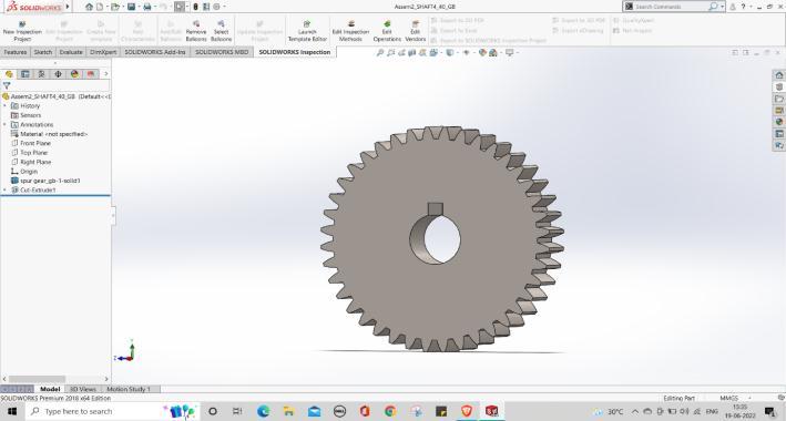
Wehaveselected20fulldepthinvoluteteethsystem.Aswe inputourmodule,systemofteethandnumberofteethinto Solidworks,itgivesustheremainingoutputs.
Design of shaft:
Torque input to individual shafts: The selected motor providesaninputpowerof6.33kWtotheinitialshaft.The firstshaftrotatesat625rpm.Fromtheformula,

WegetTorsionalmomentoffirstshaftT1=96.71N-m. Similarly,findingoutallthepossibletorsionalmomentsof all shafts, we consider the maximum one for calculation purposes.Theresultsaretabulatedasfollows:
Fig - 6:Typesofteethsystem
Byconsidering20-degreefulldepthsystem:
Addendum(ha)=m=3mm
Dedendum(hf)=1.25m=3.75mm
Clearance(c)=0.25m=0.75mm
Workingdepth(hk)=2m=6mm
Wholedepth(h)=2.25m=6.75mm

Tooththickness(s)=1.5708m=4.7mm
Toothspace=1.5708m=4.7mm
Filetradius=0.4m=1.2mm
Weights of individual gears:
Post obtaining the dimensions required for each gear, we design them on modelling software and then obtain the weightsasfollows:
Thetorquesmarkedinredarethehighesttorquesactingon therespectiveshafts.Thisbeourtorsionalmomentstobe consideredduringdesign.
Calculation and Direction of Gear Forces: There are 3 maintypesofforcesactingwhenagearpairmeshes.They areasfollows:
Tangential Force Ft: Theforceactingtangentialto the gear surface at the point of contact with meshinggear.
Radial force Fr: Theforceactingtowardsthecentre ofthegearatthepointofcontactwiththemeshing gear.
Axial Force Fa: Theforcethatactsinthez-direction alongtheshaftduetotheangleoftheteethisthe axial force. As our teeth don’t have an angle with respect to the gear base, this force for our consideration,is0.
Asourgearboxisaspurgearsystem,wewillconsiderthe tangential and radial forces of all gears for calculation purposes.
For each gear
Modified Weight of Gear: FromSolidworks,wehavethe weightofthesolidgear.Astherewillbeashaftofdiameter ‘d’ through this, we must reduce that much weight. Therefore,givinganewmodifiedweighttoworkwith.
Let,
Wnew=ModifiedWeightinNewton
Wold –SolidworksoutputweightinNewton
Wr -WeightofInnerparttoberemovedinNewton.
d–diameterofshaftinm
f–facewidthofgearinm
ρ–densityofgearinkg/m3
g–accelerationduetogravityinm/s2
Wnew =Wold –Wr
Wr =Weightofcylindricalpartofgear
Wr =
Calculating Maximum Bending Moment for each Shaft: Ouraimrightnowistocalculatemaximumbendingmoment actingontheshaftforthecalculationofshaftdiameter.This can be done in terms of ‘d’ as all values in our SFD are in termsof‘d’.
ThemaximumbendingmomentisareabetweentheSFDand theshaftaxisabovetheshaftaxisandthepointofmaximum bendingisthepointwheretheSFDgraphcrossestheshaft axis.Thus,calculatingtheareas,wegetthefollowingresults.
Determining Shaft Diameter: We will be designing the shaft using ASME code of shaft design. According to this code,thepermissibleshearstressτmax fortheshaftwithout keywaysistakenas30%ofyieldstrengthintensionor18% oftheultimatetensilestrengthofthematerial,whicheveris minimum. Therefore, τmax = 0.30 Syt or τmax = 0.18 Sut (whicheverisminimum).
Ifkeywaysarepresent,theabovevaluesaretobereduced by25percent.AccordingtotheASMEcode,thebendingand torsionalmomentsaretobemultipliedbyfactorskbandkt respectively,toaccountforshockandfatigueinoperating condition.TheASMEcodeisbasedonmaximumshearstress theoryoffailure.
were,
kb =combinedshockandfatiguefactorappliedtobending moment
kt =combinedshockandfatiguefactorappliedtotorsional moment
Mb =MaximumBendingmomentactingonshaft
Mt =Maximumtorsionalmomentactingonshaft
Shaft Number Shaft diameter (mm)

1 28
2 30
3 30
4 28
2.7 Design of keys and keyways:
Type of key: There are various types of keys. We have selected Rectangular Saddle Key. Its design has been conductedasfollows.
Fig -7:Shockandfatiguefactors
For the gearbox, it is a minor shock application. Thus, the load is applied suddenly. We have taken as intermediate valueofkb=1.5-2.0andkt=1.0-1.5.

Ourshaftmaterialis‘SteelFeE580(Sut =770andSyt =580 N/mm2).
Calculatingpermissibleshearstress, 0.30Syt =0.30(580)=174N/mm2
0.18Sut =0.18(770)=138.6N/mm2
Thelowerofthetwovaluesis138.6N/mm2andthereare keywaysontheshaft.
τmax =0.75(138.6)=103.95N/mm2
Combiningvaluesofτmax frombothaboveequations,
Design on load basis: ThematerialforkeyisSteel50C4(Syt =460N/mm2)andthefactorofsafetyistakenas3.Forkey material,theyieldstrengthincompressioncanbeassumed tobeequaltotheyieldstrengthintension.Keywaysareon thesecondandfourthshaft.
Syc =Syt =460N/mm2 N/mm2
Accordingtomaximumshearstresstheoryoffailure,
Ssy =0.5*Syt =0.5(460)=230N/mm2
b –breadthofkey
Usingmaxbendingmomentandtorsionalmomentvaluesfor eachshaft,wegetthefollowingshaftdiameterswhichare takeninaccordancewiththestandardshafttable.
h –heightofkey
l –lengthofkey
d –diameterofshaft
Industrystandardistoselectabasicdimensionof
b=h=d/4=30/4=7.5=7mm or
Taking maximum value using both equations, we get key length=28.7mm
Nowselectingfromstandardtable,
Thus,weselectthekeywithdimension (b,h) as (8,7) and a length of 30mm.
The values given in the above table are only for general guidance.Foraparticularapplication,thedesignershould consider the experience, the difficulties faced by the customer in replacing the bearing and the economics of breakdowncosts.

Asweare relativelynewto thedesigningaspect, wehave taken an estimated 15,000 hr( due to it being an intermediatevalueforaservicemachine.
Selection from Manufacturer’s Catalogue: To select the finalbearings,wewillneedradialforceacting.Asthereisno axial force, total force P = Fr. Diameter of all 4 shafts are takenintoconsideration.Thenusingmaxspeedofallshafts, wecalculatetheratedbearinglifeL10 bytheformula,

After we get this value for all shafts, we calculate the dynamicloadcapacityCby,
2.8 Selection of bearings:
Defining Bearing Life: Toselectbearings,itisnecessaryto specifylifeofthebearings.Thiscanbedonefromstandard bearingselectiontable. The recommendedbearinglifefor gearapplicationsisgiveninthetablebelow:
Thus,wegetthevaluesofCasfollows:
BasedonthesevaluesofC,wemustselectabearingfromthe manufacturer’s catalogue whose dynamic load capacity is morethanourrequirement.Thetableforselectionisgiven below.

Thefollowingtabletellsuswhichbearingsaresufficientto satisfyourrequirementandarethusselected.
2.9 Casing Design:
Casing consideration: Followingstepshavebeentakeninto considerationwhiledesigningthecasingofthegearbox.
Compact
Weightoptimisation

Leakproof(bearingfittedincasing)
Visual Representation: Thepartofthecasingwhichholds thegearboxlooksasfollows.
2.10 Final Gearbox assembly:
Final Gearbox assembly: ThefinalGearboxassemblywith correctedvaluesisasfollows:
3
Nowthatwehadalltheparametersrequiredfordesigning thegearboxonCADtools,theCADmodelsforallthegears, shafts,bearings,andthecasingwascreated. TheCADwas modelledinSolidworkssoftware.


Deformation Results:
3.3 Gearbox
analysis: Analysis of Gearbox
ThegearpairshavebeenanalyzedonANSYS18.1software. Analysis of components can be done in various ways like static,dynamic,transient,etc.dependinguponapplication. Staticanalysisisconcernedwithdeterminationofresponse ofageartosteadyloadswhoseresponseremainsunchanged withtime.Theresponseofthegearisexpressedintermsof stress,strain,displacement.Thetoolusedinstaticanalysisis Staticstructural.
Procedure: The finite element analysis procedure of the spurgearwasgivenbelow:
1. A three-dimensional model of the spur gear was createdusingthepro/engineerCADsoftware.


2. Thematerialpropertiesweredefinedforgears.
3. The model was meshed using finite element software.
4. Boundary conditions for ANSYS Workbench as mentionedbelow.
5. Fixeddisplacementconstraintwasappliedongear.
6. Momentwasappliedongear.
7. Toarrestthedisplacementonx,y,zdirectionsand rotations on x, y directions remote displacement constraintisappliedonpinionsurface.
Contacts – Frictionlesscontactsbetweenthegearpairsand thegearandshaftpairs.
Boundary Conditions – Torqueshavebeenappliedtothe inputgearsurfaces.
Material – Cast Iron has been considered for all the gear pairs.
Factor of
The value obtained for the FOS for all the gear pairs is mentionedbelow–


Hence, we can conclude that the design is within the permissiblelimitsforthegivenmaterialandgeometry.
Analysis of shafts:
ThetoolusedinstaticanalysisisStaticstructural.
Procedure: The finite element analysis procedure of the shaftswasgivenbelow:


1. A three-dimensional model of the shafts was createdusingthepro/engineerCADsoftware.
2. Thematerialpropertiesweredefinedforshaft.
3. The model was meshed using finite element software.
4. Boundary conditions for ANSYS Workbench as mentionedbelow.
5. Fixeddisplacementconstraintwasappliedongear. Contacts – Fixedcontactshavebeenprovidedattheendsof theshafts.
Boundary Conditions – Forceswereappliedontheshaftas PointloadsandUDL.
Total Deformation:
4.2 Shaft Analysis
5. CONCLUSIONS
Inconclusion,astandarddesignprocedureforthedesignof this 8-speed gearbox was followed considering various researchpapersandtextbooks.Normally,inlathemachine applications, 6 speed gearboxes are used and using an 8speed gearbox will provide more operating speeds along with offering more smoother and uniform machining operation as the intervals between two successive speeds will reduce.Post designing, thoroughanalysisconsidering theworkingandstaticconditionsofthegearboxwasdone andallcriticalparameterswerefoundtobewellwithinthe permissiblerange.
REFERENCES
[1] N.SivaTejaandK.DineshBabu,“Designandanalysisof differentialgearboxinautomobiles”IJMET,vol.8,May 2017,pp.175
185.
[2] PNVSaiMaheshandMVVSaiRam,“DesignandAnalysis ofa4-speed,dualinputhybridgearbox”IJPAM,Volume 118,No.24,2018.
[3] YeMintandZawMawOo,“AnalysisofGearBoxDesign inheadstockforCNClathemachine”IJSRP,Volume9, Issue8,August2019.
[4] DMohammedRafiandMr. BRajaKumar,“Designand development of gearbox for multi-purpose milling machine”AIJREAS, Volume1,Issue12,Dec2016.
[5] Pawan Kumar and M. Y. Patil, “Design and Thermal Analysisofhelicalgearbox”GRA,Volume2,Issue4April 2013.
[6] A.Y.VGopiKrishnaandR.V.Kiran,“DesignandAnalysis oftwostagereductiongearbox”IRJET,Volume6,Issue 12,December2019.
[7] ThiteSagar,“Modalandstressanalysisofgeartrainin portalaxlesystem”IJERT,Volume6,Issue5,May2017.
[8] Nihad Hassan Talib and Gopi Krishna, “Design and finite element analysis of high-speed compressor gearbox”IJIRCT,Volume1,Issue1,2015.
[9] RejiMathewandLintoPAnto,“GearboxdesignforCNC lathe”IRJET,Volume5,Issue4,April2018.
[10] JoginderSinghamdMRTyagi,“Analysisofstressesand deflectionsinspurgear”IJMET,Volume8,Issue4,April 2017.
[11] SushilKumarTiwariandUpendraKumarJoshi,“Stress Analysis of mating involute spur gear teeth” IJERT, Volume1,Issue9,November2012.