Suspension and chassis design, and steering calculations for SAE BAJA All-Terrain Vehicle
Gurpreet Singh1, Abhinav Kumar , Saurabh Menwal31-3B.E. Mechanical Engineering, Panjab University SSG Regional Centre, Hoshiarpur, India
Abstract - The purpose of this research paper is to provide an effective framework of design criterion, equations, & basis for design trade-offs to carry out suspension and steering calculations, suspension geometry design, and design decisionmaking for single-seater All-Terrain Vehicle for off-road racing specifically for student BAJA competitions.
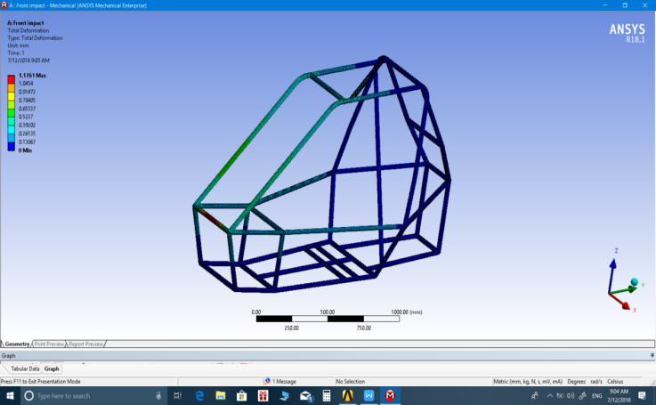
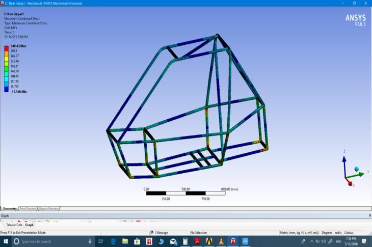
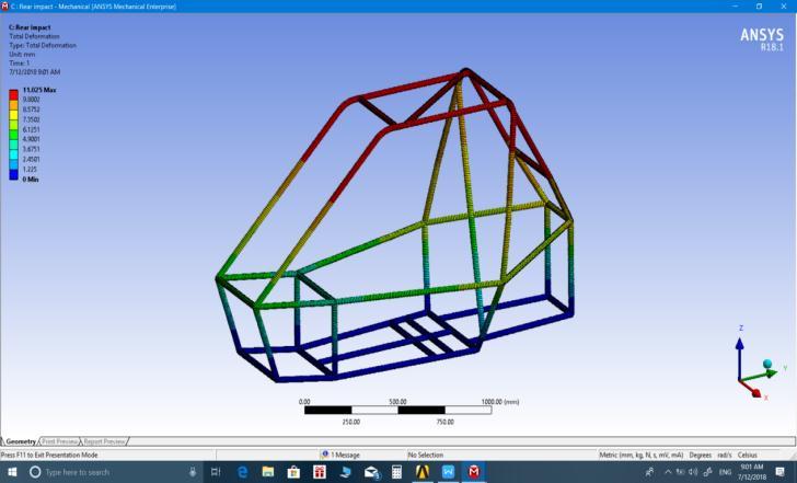
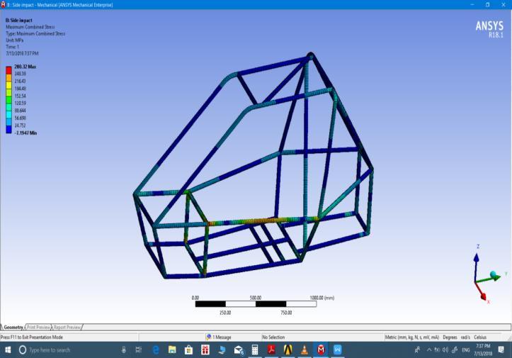
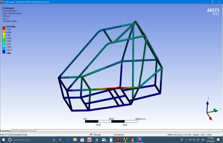
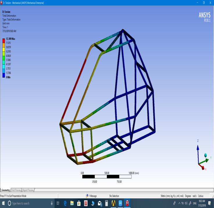
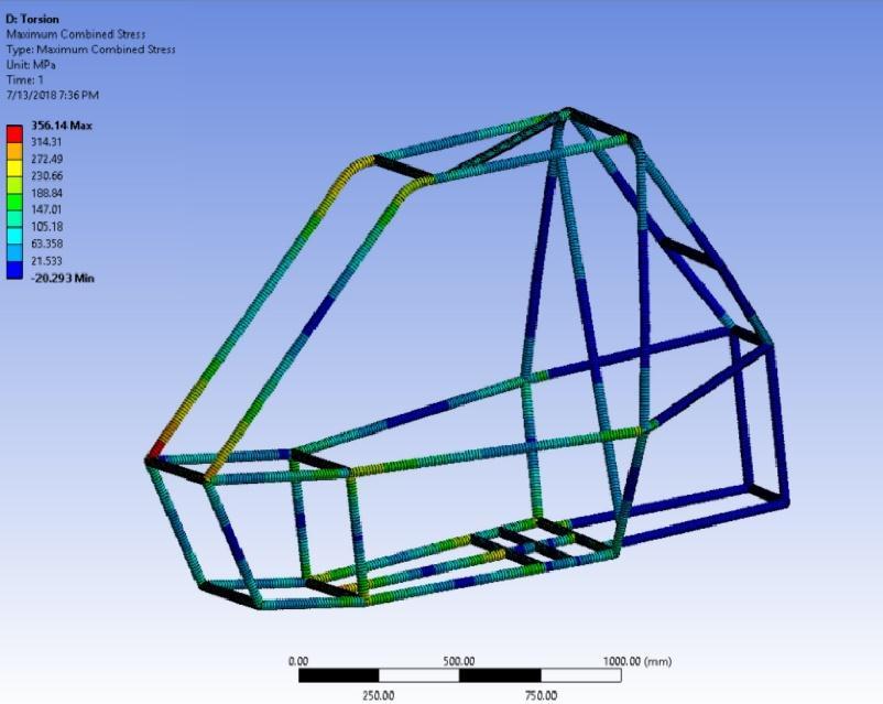
Following guidelines set by the BAJA Student rulebook, the ATV chassis was designed considering driver safety and ergonomics. A physical model of the chassis was created using PVC pipes for design verification. CAE validation of the chassis was done for the front, side, and rear crashes, torsional stability, and rollover, also the suspension wishbone A-arm deformation analysis was conducted.
Suspension and steering geometries were optimized using LOTUS software.
Keywords- Baja,Suspension,Steering,Design, CAE,Chassis, ATV
1. INTRODUCTION
BAJA SAE is a national level competition conducted annually bytheSocietyofAutomotiveEngineers(SAEIndia)todesign, make and race single-seating off-road cars. It has been running successfully for the previous 10 editions and our collegiateteam‘8MILES’wasparticipatinginBAJA2019.
All-Terrain Vehicle is a vehicle that travels on low-pressure tires and is designed to handle a wider variety of terrain. Since it is made to run on different types of terrain, thus stability, vehicle behavior, and driver comfortability in the vehicle are the foremost problems [5]. So the aim is to develop a suspension and steering system which gives good performance, and endurance and provides maximum directional control and stability to the vehicle. The steering knuckleisadisparagingcomponentofanyautomobile Italso comesasthehigheststresscarryingpartofthevehicle.
Toensuredriversafetyandstandardizeconstraintsforevery team SAE BAJA provides an extensive set of guidelines in a rulebook[4].Youaresupposedtoadheretoitfor thedesign and manufacturing practices of your BAJA Buggy. The
rulebook also serves as design guide for the vehicle’s roll cageandothersub-system’sdesign.Tokeepthecompetition fair, BAJA bounds every participating team to use the same engine,Briggs&Stratton1450series10HPengine.
2. SUSPENSION AND WHEEL ALIGNMENT
2.1 Objective
The suspension sub-system play a pivotal role in the vehicle dynamics of an ATV as it helps the vehicle to perpetuate the rigorous environment of off-road racing. It also aids the vehicle to sustain the hard impact of bumps and ditches of the rough terrain. Student teams have faced difficulty in selecting suspensions, so it’s always advisable to focus more onthispartinitiallyinvehicledesign.Afewfactorsinvolved inmakinganoptimumsuspensionsystemforthevehicleare the roll center’s height and its dynamic fluctuation and camber gain and scrub radius. A design engineer should carefully balance these factors considering on all the design trade-offs[2].
2.2 Design Contemplations
Thedesignoutputofasuspensionsystemshouldbeto:
● Improvethevehiclehandlingandcontrol
● Providesufficientrideheightandtotalwheeltravel.
● HaveSufficientlyrigidanddurable
● Control movement at the wheels during vertical suspensiontravelandsteering,
● Limit chassis’ rolling during cornering, to prevent rollover, decrease roll camber, and therefore decreasesteeringreactiontime.

2.3 Vehicle Specifications
Table -1: WheelalignmentanglesandSuspensionResults
Camber
3° Enhances stability and cornering ability
Caster 7° Enhances stability and aids in self-centering.
King Pin
Inclination
31° Returntheabilityofthewheelto astraightposition
RollCenterFront 156’’ Morechassisrollsinturns
Suspensiontravel 6’’ ForFoxfloat3suspensions
Groundclearance 13inches -
2.4 Wishbones
The double-wishbone suspension system was chosen as it hasthefollowingadvantages:
• It gives more flexibility in designing the suspension system i.e. we can control roll center variation and roll centerheightaspertherequirementsofthevehicle[6]

• It is sturdy and hence easily sustains the large bumps and frequent impacts that are desirable for the front suspension[6]
This system requires more physical space than other suspension systems (McPherson strut, trailing arm suspension systems) The vehicle Chassis was designed taking into account the extra space essential for double wishbones.
Tostartthesuspensiondesignonemustbeginbyconcluding on the front geometry of the vehicle. The design of the front geometryrequiresthefollowingparameters[2]:
● Knuckle’slength
● DoubleA-arms’lengths.
● Inclinationofkingpin.
● Vehicle’sJounceandRebound.
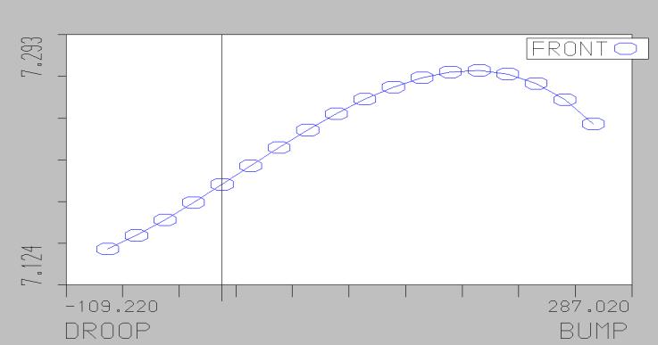
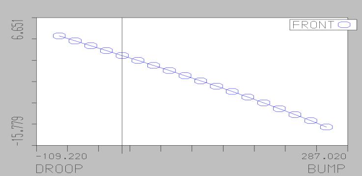
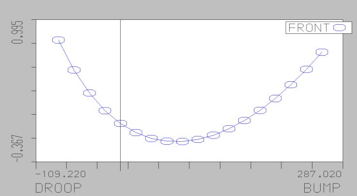
The geometry optimization for suspension and steering was done using LOTUS suspension software. Suspension hard points are the areas where suspension connects to the chassis, they command the suspension kinematics. Coordinatesofthesepointsaretakenasinputinthesoftware and the vehicle’s dynamic motion during droops and bumps andsteeringmotionissimulated.
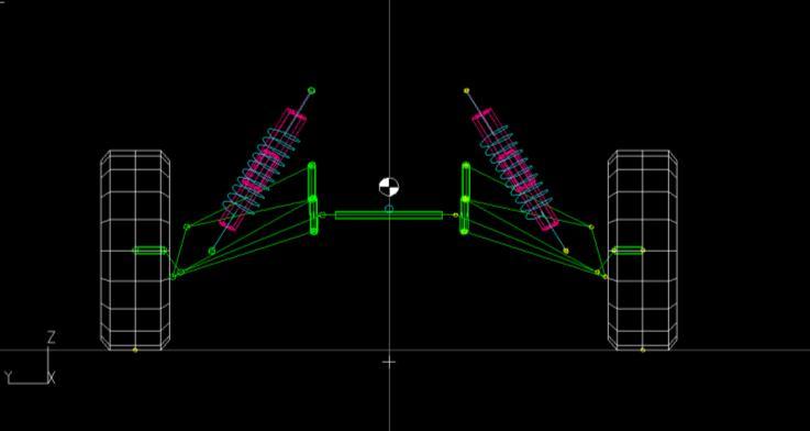
Finer geometry optimizations were done using guidelines from Carroll Smith, “Tune to win” [2]. Graphs of Camber, caster, and toe angles versus droop/bump were extracted fromLOTUS.Variations intheiramplitudeswereadjustedto bewithindesiredvaluesbychanginghardpoints.
All-terrain high-performance tires were chosen with dimensions: 22 X 7 X 10: (external diameter x tire width x rim diameter) (in inches) after market research and understanding the experience of teams in previous competitions.
3.1 Objective
● To provide directional stability to the vehicle, ease of movinganddirecting,comfortablystabilizingafterturns, andmaximumdispersionofroadshocks[1].
● To facilitate straight-ahead recovery after completing a turn

● Tokeeptheturningradiusminimumindesign
● Tohaveexcellentrollingofthetiresaboutasolepoint
3.2 Design decisions and computations
After a lot of research and study, it was decided that Ackermansteeringgeometryistheeasiesttoimplementand hasbeentestedallovertheglobeforBAJAvehicles.
Ackermann’s steering mechanism is a 4-bar linkage mechanism. It consists of no sliding pairs. As there are only turning pairs, hence it minimizes the wear and tear of the mechanism. The mechanism has the following advantages [3]:
● Itreducesthesteeringlaborofthedriver.
● Itconsumesminimumspace
● Itinvolveslessno.ofverylightweightlinkages.
● Due to the small no. of linkages probability of wear and tearofjointsislowest.
The steering wheel’s rotational movement is transferred to the pinion through the use of universal joints. The rotary motion of the pinion is converted into reciprocal movement of the rack, this linear motion of the rack gets transferred to

the ball joints and tie-rods and then to the wheels supposed tobesteered
After numerous iterations in LOTUS software, below mentioned values were chosen for their respective properties.
PROPERTY VALUE
Turningradius 2.528m
Steeringangle Inside-40degrees Outside-25degrees
No.oflock-to-lockturns 540
Racklength 4.25inch
Tierodlength 0.3683m

4. ROLL CAGE DESIGN
The roll cage is one of the most critical components for driver’s protection in every vehicle. Principal aspects of the chassisfocusedonthedesignandimplementationoftheroll cage were driver safety, suspension and drivetrain integration, structural rigidity, weight, and operator ergonomics.
BAJA rulebook {was religiously followed to decide upon the sizeandorientationofeveryrolecagepipemember.
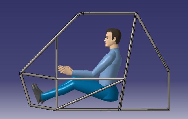
The rear roll hoop’s design was made for the safety of our driverconsideringtheclearancesandanglesgovernedbythe rulebook. Lateral Diagonal Bracing was determined during thePVCprototypingprocesswithcarefuldeliberationon the stabilityofthewholestructure.Thelateralsidememberwas chosen such that the driver is able to steer the wheel comfortably and apply force to the brake and acceleration pedals with his feet to their limits. The slightly crouched sitting position of the driver was preferred keeping in mind thealertnessandsteadinessrequiredinoff-roadracing.
4.1 Design considerations
● Easymanufacturing
● Durableandcompact
● LightweightandErgonomicdesign
● Favor quick assembling and disassembling of vehicle components
● Driversafety
4.2 Pipe material and size selection for Roll Cage
Theselectionof theproper materialforthebuildingof aroll cage is very important as it provides the desired strength, reliability, safety, and endurance to the vehicle. The strategy behind selection of the material was weight, weldability, goodbendingstiffness, and maximumstrengthforthepipes. After a lot of market research we narrowed down the
selection to AISI 1018 and AISI 4130 Steel materials. Based onthecost,availability,andpropertiesofthesetwoalloyswe finalizedAISI1018Steel

Table 4:Propertiesofpipematerials MATERIAL
4130
PHYSICAL PROPERTIES
According to the rulebook, the primary member should be circular steel piping with an externa diameter of 1.25 inches and a wall thickness of 0.067inch. As a constraint was provided on the selection of the size of secondary members, the minimum wall thickness must be 0.035inch and the minimum outside diameter must be 1 inch. The bending strength and ease of manufacturing were also taken into considerationwhiledecidingthecross-sectionofthepipe.
4.3 Finite Element analysis of roll cage
The followingresultswere obtained during differenttestsof rollcage:
Table 5: FEAanalysis results of Roll cage with Factorof Safety


4.4 Driver Ergonomics
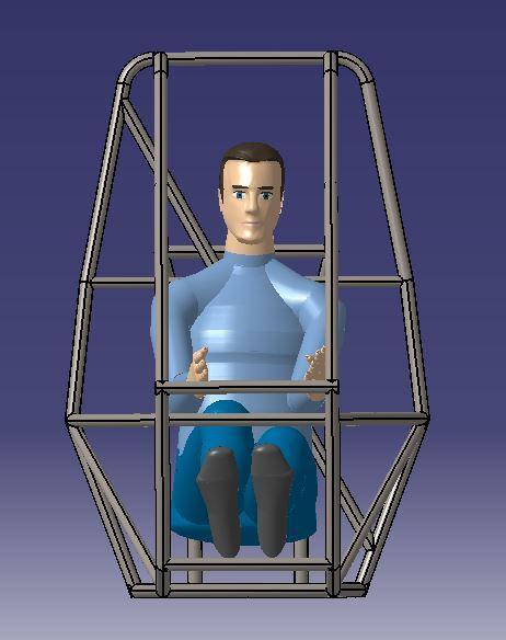
The following factors were considered in creating an ergonomicallysuitedrollcage[4]:
● Seatinclination[4]
● SteeringWheellocation[4]

● Designingofthefootboxarea[4]
● DriverSafety[4]
● Seatlocation[4]
CATIA V5 was used to do the human ergonomics test and a prototypemodelwaspreparedwithPVCpipes.


Vehicle Ergonomics were decided based on the following features:
● Centerofgravityofthevehicle
● Weightbalancing
● The posture of the driver was decided so that any of its bodypartsdonotinterferewiththecomponents
● Properpedalinganditslocationforeasyoperationofthe vehicle
● Seat and placement of the other components of the vehicleforsafetyandcomfort.
Also, FEA analysis of critical components make the design fail proof and saves the cost of numerous cycles of prototyping.
6. ACKNOWLEDGMENT
We would like to offer our gratitude towards our faculty advisors for the project, Dr. Manu Dogra and Mr. Gaurav Saini, M.E. Their persistent support and guidance to our team throughout the journey helped us accomplish our project goals and pushed us to advance further in automobile design and become better engineers. We also acknowledge the financial support of our college to make thisprojectasuccess.
5. CONCLUSION
In conclusion we can say that designing and manufacturing an ATV for student competitions makes upcoming engineers wellversedwitheveryaspectofautomobileengineering.
The use of LOTUS software is a very beneficial method to designthesuspensionandsteeringgeometry.Itallowsuseto testandtrial differentdesignparametersandoptimize them tofreezeonthefinalvalues.
7. REFERENCES
[1] Thomas D Gillespie, “Fundamentals of vehicle dynamics”,SAEInc.,1992,pp.291-293
[2] Carroll Smith, “Tune to win” , Aero Publishers Inc., 1978,chapter4,5
[3] William F. Milliken, Douglas L. Milliken, “Race Car VehicleDynamics”,SAEInternational,1994,chapter5.
[4] Baja SAEINDIA Rules, 2019 Collegiate Design Series, PartB
[5] Nitish Malik, Prakhar Agarwal ‘Fine-Tuning Of the Suspension System of Baja ATV’. ISSN : 2248-9622, Vol.7,
[6] Issue 8, ( Part -2) August 2017, pp.94-98 https://www.ijera.com/papers/Vol7_issue8/Part2/P0708029498.pdf

[7] Yogesh Sharma, Rohit Kumar Garg, Rishabh Raj Bhargava,AadityeshwarSaranSinghDeoetal."Design and Development of Single Seat, Four Wheeled AllTerrainVehicleforBajaCollegiateDesignSeries",SAE International,2015
8. AUTHORS
First Author – Gurpreet Singh, B.E. Mechanical Engineering, Panjab University SSG Regional Centre, Hoshiarpur,gsbasra96@gmail.com
Second Author – Abhinav Kumar, B.E. Mechanical Engineering, Panjab University SSG Regional Centre, Hoshiarpur,sukoiabhinav97@gmail.com
Third Author – Saurabh Menwal, B.E. Mechanical Engineering, Panjab University SSG Regional Centre, Hoshiarpur,saurabh.mn95@gmail.com
