
Investigating the Effect of Prestressing CFRP Laminate and Mechanical Anchorage to Strengthen Steel Beams Under Flexural Loading
Mohamed A. Gharib 1 , Ali El Awadi 21 alfanar Engineering Services,
mo.g.abdul.76@gmail.com2 Teaching and Research Assistant, Zagazig University, Zagazig, Egypt,

Abstract - The use of composite materials, such as Carbon Fiber Reinforced Polymer (CFRP), as a strengthening and retrofitting method for steel beams, has gained widespread attention in recent years. This study aims to improve the understanding of the behavior of steel beams reinforced with CFRP laminates with mechanical anchorage. The previous analytical studies did not include the effect of mechanical anchorage. This study examines the behavior of steel I-beams strengthenedwithprestressedcarbonfiberreinforcedpolymer (CFRP) laminate and fixed with mechanical anchorage under flexural loading. An experimental program, a closed-form analytical model, and a finite element analysis are presented in this investigation. Ten steel beams were experimentally investigated with and without mechanical anchorage and at various prestressing levels. An analytical and a finite element model considering the mechanical anchorage were developed to predict the stresses in the CFRP-Steel beam adhesive layer at the contact area. The models were validated with experimental results. The mechanical anchorage successfully increased the bond strength and changed the failure mode from premature debonding to CFRP rupture. The study highlights the importance of considering mechanical anchorage in analytical models for bonded CFRP laminates to ensure the preservation of prestressing force.
Key Words: CFRP, Mechanical Anchorage, Prestressing, CohesiveZoneMethos,CrackPropagation.
1. INTRODUCTION
TheuseofCFRPlaminateinretrofittingsubstandardsteel beams is not popular as its use for retrofitting concrete structures[1&5].Thestrengtheningprocessincludesthe adhesionofaCFRPlayertothesteelbeamlowerflange[2& 3] This configuration has a major problem which is the debondingfailureofbetweenthesteelbeamandtheCFRP strip.Itwasfoundfrompreviousstudiesthatprestressing theCFRPlayermayimprovetheperformanceutilizethefull capacityofthestrengthenedhybridbeam.
Previous investigations found that prestressing the CFRP laminates is beneficial to the strengthening process [4]. Several techniques are suggested to apply the pretension force to the CFRP laminate in such a configuration. Mechanical anchorage is required for the effectiveness of these techniques. The proposed mechanical anchorage is
cengag2@gmail.comappliedatbothendsofthelaminate. Thiscanresultinan enhanced ductile behaviour and increase the prestressing force that can be applied. Using mechanical anchorage improves the serviceability and strength of the composite sections[2&6].Previousstudies thatemployedthefinite element method to investigate the behaviour of this strengtheningtechniqueusedthesmearedcrackconceptto analysetheinterfacialstressresultingfromthecontactzone betweenthesteelbeamandtheCFRPlaminates[7].Onthe other hand, the discrete damage method reflects the final damaged condition more accurately. It models the crack propagationthroughadisplacement–discontinuityusingan interface element that separates two sides of the crack modelled using solid elements such as the cohesive zone method (CZM). This method presupposes that the stress between two surfaces of two materials does not dissipate immediatelywhendamageisinitiatedattheirinterface.The cohesivematerialbehaviourcontrolstheinterfacebetween theseparatingsurfacesofthesteelbeamandthelaminate. TheCZMactasaspringbetweentheelementconnectingthe modelledsurfaces.However,thestiffnessoftheelementis partofthestructuralstiffness,sotheelementdeformation will occur during the loading of the laminate. Analytical modelsinpreviousstudieswereintroducedtocalculatethe shear and normal stress in the contact zone between the steel surface and the CFRP layer attached to it [8, 9 &10]. However,thesestudiesdidnotconsiderthesignificanteffect ofmechanicalanchorageifemployed.
Thisstudyutilizedanexperimentalprogramtoevaluateand analyze the behavior of steel beams reinforced with prestressed CFRP using mechanical anchorage under flexural loading at two points. A total of ten steel beams reinforcedwithvariousconfigurationsofprestressedCFRP laminates were subjected to static flexural loading until failureoccurred. Thespecimensweresimulatedusing the CZMapproachandfiniteelementmethod.Theaccuracyof theFEmodelwasvalidatedbycomparingitwiththeresults obtainedfromtheexperimentalprogram.TheFEmodelwas then utilized to evaluate the impact of increased prestressing.Furthermore,ananalyticalinvestigationwas introduced to predict the interfacial shear and normal stressesontheadhesivelayeroftheexaminedbeams.The analyticalmodel'sfindingswerecomparedagainstboththe FEMandexperimentalprogramresults.
2. THE EXPERIMENTAL PROGRAM
The experimental program considered several key factors, includingtheprestressinglevels,yieldstrengthofthesteel beam,andmechanicalanchorageimplementedatbothends of the CFRP laminate. The jacking system setup shown in Figures (1) and (2) is used to apply the load to the strengthenedbeams.


50 Yes 25
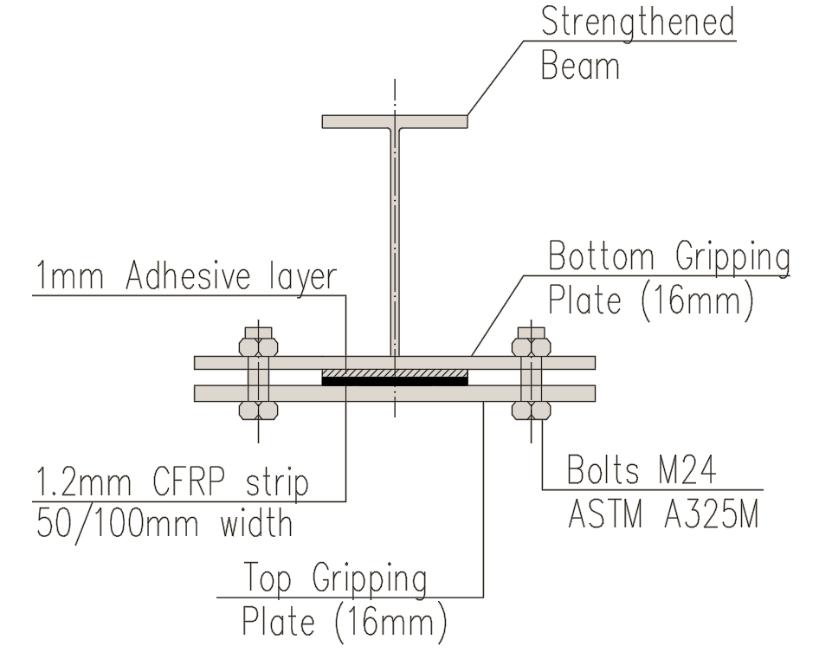
TheCFRPlaminateusedtoreinforcethespecimensis100 mm wide, with the exception of TB and B5-25-AN, which havea50mmwideCFRPstrip.ThethicknessoftheCFRP laminatesforallspecimensis1.2mm.SpecimenB6-45-ANNAD features a 100 mm pre-stressed CFRP laminate and mechanical end anchorage, but no adhesive layer was appliedbetweenthesteelbeam'slowerflangeandtheCFRP laminate.Figure(3)illustratesthebeam'scross-sectionand theCFRPlayer.
2.1 Description of the Beams
The experimental program's test specimen details are presentedinTable(1).Thefirstspecimenhasasectionsize ofIPE160,whiletheotherninebeamshaveacross-sectionof W6x20,withasteelbeamlengthof2.9m.SpecimenCB2was reinforcedwithbondedCFRPandwasnotprestressed.The CFRPlaminatethicknessusedforallspecimenswas1.2mm.
2.2 Material Properties
ThemechanicalpropertiesofthesteelbeamandtheCFRP stripsweredeterminedthroughstandardtestingandfrom themanufacturer'sdatasheet.Theaverageyieldstrengthof thesteelbeammaterialis390MPa,anditsultimatetensile strengthwasmeasuredtobe560MPa.
TheCFRPstripsusedinthisinvestigationconsistofpitchbasedcarbonfibersandepoxyresin,withthicknessesof1.2 mm and widths of 50 mm or 100 mm. The fiber volume fraction of the strips is 68%. The CFRP laminate has an average ultimate strength of 3,100 MPa and an average measuredelasticitymodulusof165GPa[27].
Atwo-componentepoxyadhesivewasutilizedtobondthe CFRP laminate to the steel beam's surface. The adhesive's mechanical properties, as provided by the manufacturer's datasheet[28],arelistedinTable(2).
-2: Propertiesoftheepoxymaterial
2.3 Test Set-up
Figure(1)depictstheexperimentalsetupusedinthisstudy, whichconsistsofsimplysupportedbeamssubjectedtotwopoint loads. The load was applied to the beam using a universal testing machine. To measure the deflection, a displacement transducer was installed at mid-span. Additionally, strain gauges were mounted on the CFRP laminateandatthemid-spanofthebeamflangestomeasure strain.
2.4 Experimental results
2.4.1 Failure Modes
In this study, applying prestressing to the CFRP laminate resultedinaproportionaldecreaseindeflectionanddelayed prematuredebondingfailure.ThecontrolbeamsCB-1and CB-1Afailedinatypicalflexuralmanner.Ontheotherhand, beam CB-2, strengthened with non-prestressed CFRP laminate,experienceda1.2%increaseinthefailureloaddue tolaminatedebonding.
CFRP-prestressedbeamsB1-25-NAandB2-45-NAfaileddue to debonding of the CFRP laminate from the steel bottom flangeimmediatelyafterreleasingthegripanchorat both endsofthebeam.However,CFRP-prestressedbeamsB3-25AN and B5-25-AN with end anchorage and Fy = 390 MPa failedinatypicalflexuralmanner,withtheCFRPlaminate experiencing a sudden rupture failure and a significant increase in the failure load compared to the nonstrengthenedcontrolbeamCB-1.Thesebeamsdevelopeda fullplastichingeatfailurewithoutencounteringpremature debonding.Thesamefailuremodewasobservedforbeam B4-45-AN,butwithalowerachievedstrengthenhancement of3.3%inyieldload.
The behavior of beam B6-45-AN-NAD, which had end anchoragebutnoadhesive,wassimilartothatofbeamswith endanchorageandadhesiveintermsofflexuralbehavior, buttheincreaseinfailureloadwaslessthanforspecimens strengthenedusingtheadhesivelayer,at7%comparedto the original non-strengthened beam CB-1. The CFRP laminateinthisbeamrupturedataloadof186kN,earlier thaninthecorrespondingspecimenwithendanchorageand adhesivelayer.

B1-25-NA 64.8 15.16
B2-45-NA 76.33 16.48
Table-3c: Resultsoftheexperimentalinvestigation-
The load deflection response of specimen B3-25-AN was compared to that of the control beams CB1 and CB2. The yield load for specimen B3-25-AN was measured to be 194.66 kN at a corresponding deflection of 21.07 mm, indicatinga 13%increaseintheyieldloadcapacityofthe combinedstrengthenedsectioncomparedtocontrolbeam CB1. During the plastic stage, the specimen experienced a loaddrop,combinedwithasuddendeflectionatmid-span caused by CFRP rupture at a load of 199.7 kN and a corresponding deflection of 37.05 mm. The specimen exhibitedasecondandfinalruptureataloadof197.8kNat acorrespondingdeflectionof57.53mmbeforethesection becameun-strengthenedandhadthesamebehaviorasboth controlbeamsuntilfinalfailure.
2.4.2 Load-displacement relationship
ThespecimenTBfailedduetolateraltorsionalbuckling,but nodebondingorCFRPrupturewasobservedduringthetest. ThepredictedyieldloadofthespecimenwasPy=93.3kN. However,basedonexperimentalresults,themeasuredyield loadwas108.16kNatacorrespondingdeflectionof22.44 mm.Thisindicatesa16%increaseintheyieldloadcapacity ofthestrengthenedsectionwhencomparedtothepredicted yieldload.
The load deflection response of specimen B5-25-AN was comparedtothatofthecontrolbeamCB1.Duringthetest, therewasnodebondingorCFRPruptureobservedinB5-25AN.TheyieldloadofCB1was172.7kNatacorresponding deflectionof20.46mm,whereastheyieldloadofB5-25-AN was 195.2 kN at a corresponding deflection of 26.28 mm, indicatinga 13%increaseintheyieldloadcapacityofthe combinedstrengthenedsection.ThefinalfailureloadofB525-ANwas200.7kNatacorrespondingdeflectionof93.45 mm, while the final failure load of CB1 was 187 kN at a correspondingdeflectionof82.63mm.
Specimen CB2 attained its yield capacity without any observedprematurefailure.TheyieldloadofspecimenCB2 wasmeasuredtobe174.8kNatacorrespondingdeflection of 19.5 mm, indicating that the CFRP strengthening, with neither prestressing nor mechanical anchorage, only increased the yield strength of the combined section by 1.2%. However, the specimen experienced a debonding failureandasuddendropintheappliedloadafterfurther loading. The debonding load for specimen CB2 was measured to be 193.2 kN at a corresponding deflection of 29.33 mm. After debonding, the specimen was unstrengthened and behaved similarly to control beam CB1 untilfinalfailure.
The load deflection response for specimen B4-45-AN was compared to that of control beam CB1A. Both specimens reachedtheiryieldcapacitywithoutanyprematurefailure observed.ThemeasuredyieldloadforspecimenCB1Awas 161kN atacorresponding deflectionof22mm, whilethe measuredyieldloadforspecimenB4-45-ANwas166.3kNat acorrespondingdeflectionof23.34mm.Thisindicatesonly a3.3%increaseintheyieldloadcapacity.Bothspecimens, B6-45-AN-NAD and CB1, exhibited similar load deflection responses.Thespecimensfailedinatypicalflexuralmanner, with no premature failure observed. The measured yield load for the specimen was attained with no significant differencecomparedtothecontrolbeam.
Specimen B6-45-AN-NAD showed only a 7% increase in yieldloadcapacitycomparedtothecontrolbeamCB1,witha measured yield load of 184.3 kN at a corresponding deflectionof24.71mm.Whichshowshowistheeffectofthe lack oftheadhesivelayer onthe responseandtheoverall strength. However, after further loading, the specimen experienced a rupture failure with a sudden drop in the appliedload.Themeasuredruptureloadforthisspecimenis 201.33kNatacorrespondingdeflectionof39.67mm.The specimenalsoexhibitedasecondandfinalruptureataload of 202.33 kN at a corresponding deflection of 55.14 mm before the section became un-strengthened and behaved similarlytothecontrolbeamuntilfinalfailure.
Figure (5) shows the effect of adding CFRP strengthening andtheadvantageofprestressingtheCFRPlaminatewhich enhancedtheoverallperformanceofthebeam.
3 FINITE ELEMENT ANALYSIS
3.1 Finite element model
ThefiniteelementprogramANSYS®(version13)wasused inthisinvestigation[17].Athree-dimensionelement(3DFE) model was developed to simulate the geometric and nonlinearmaterialbehavioroftheinvestigatedbeams.Fournodeshellelement,(Shell281),wasusedtomodelthesteel beam. Eight-node brick element (Solid 185) was used to modeltheadhesivelayerandtheCFRPstrip[11].Thearea between the CFRP laminate and the steel beam was simulatedusinga3-D8-nodelinearinterfaceelement(Inter 205).Thiselement,whenusedwiththe(Solid185)element, simulated the interface between two surfaces and the subsequentseparationprocess,wheretheseparation was represented by a gradual displacement between nodes representingthetwobondedsurfaces.
3.2 Boundary conditions
Beams are symmetric about their longitudinal axis, and thereforeonlyhalfofthebeamsweremodeled.Thebeams weremodeledwitharollersupportatoneendandahinged supportattheotherend.Twostiffeningplateswerewelded tothesteelbeam'sflangeatthepointofloadingandatthe supports to prevent stress concentration. The load was applied incrementally as a static load, following the automaticloadcontrolscheme.Themodifiedstandard/static generalmethodwasusedfortheanalysis.Figure(6)depicts the simulated beam with applied forces and boundary conditions.
Fig -6:Simulatedbeamwithboundaryconditions
3.3 Materials modeling
Inthisstudy,theclassicalelastic-plasticmaterialmodelwith strain hardening was used to represent the steel I-beam, which has a bilinear stress-strain relationship for both compressionandtension.TheCFRPstrip,ontheotherhand, has a linear stress-strain relationship until failure. When brittle materials undergo tensile fracture, microcracking, tortuous debonding, and other internal damageprocesses occurprogressivelyandeventuallyleadtotheformationofa geometricaldiscontinuitythatseparatesthematerial.Ifthis discontinuityoccurswithinthesamematerial,itiscalleda crack,whileifitoccursbetweentwodifferentmaterials,itis referredtoasdebondingordelamination.Inthisresearch, the cohesive zone modelling approach (CZM) is used to simulate debonding. To implement this approach, a CZ materialwascreatedandassignedtothecontactelementsin theinterfacezone,anditsbehaviorisdescribedintermsofa traction-separation equation instead of the traditional engineering stress-strain (σ − ε) equation. To ensure the zerothicknessoftheelement,coincidentoppositenodesof the cohesive element are defined. The CZ material was characterizedbythreeconstants:thematerial'smaximum allowedstress,theenergyreleaserateatnormalseparation, andthetangentialdisplacementatmaximumstress.

3.4 Prestressing Effect
Therearemany methodsthatcanbeused tosimulatethe prestressing effects on the CFRP laminates. In this investigationtheconstantprestressingeffectinthelaminate wasappliedinthelongitudinal(x)directiontothespecific materialoftheCFRPusingthesoftwarepackage.

3.5 The Simulated Beams
Thepresentstudywasconductedintwostages.Stageone focusedonvalidatingthepresentfiniteelementanalysisby analyzingnumericallythesteelbeamsthatwerepreviously tested in the experimental program. Five beams were
simulatedatthisstagetovalidatethefiniteelementmodel. Theseincluded:
1. CB1: Control beam with no CFRP strengthening, havingasteelyieldstrengthof390MPa.
2. CB1A: Control beam with no CFRP strengthening, havingasteelyieldstrengthof350MPa.
3. CB2: Control beam with only one CFRP strengthening strip, 100mm wide, and a yield strengthof390MPa.Thisbeamwasnotsubjected to any prestressing force. The CFRP strip was attached to the steel beam with a 1 mm layer of adhesive,withouttheuseofmechanicalanchorage.
4. B3:Beamstrengthenedwitha100mmCFRPstrip. TheCFRPstripwassubjectedto25kNprestressing force.Theyieldstrengthofthesteelbeamwas390 MPa, and the CFRP laminate was attached to the steelbeamusinga1mmlayerofadhesivematerial andtwosetsofmechanicalanchorage,oneateach endoftheCFRPlaminate.
5. B4:BeamsimilarinconfigurationtoB3,butwitha prestressingforceof45kNandayieldstrengthof 350MPa.
In the second stage of the study, the FEM model was extended to investigate the effect of increasing the prestressinglevelonthebehaviorofthebeam.Thevalidated FEMofthe simulated beamsfrom stageI wasmodified to evaluate the impact of increasing the prestressing force appliedtotheCFRPlaminate.Thebeamstestedatthisstage were:
1. B3-15%:Thisbeamhasthesameconfigurationas beam B3 introduced in stage I. However, the prestressingforceappliedtothisbeamwas15%of theultimatetensilestrengthoftheCFRPstrip.
2. B3-40%: The prestressing force applied to this beam was40%oftheultimatetensilestrength of theCFRPstrip.

3. B3-70%: The prestressing force applied to this beam was70%oftheultimatetensilestrength of theCFRPstrip.
4 PROPOSED ANALYTICAL MODEL AND THEORETICAL APPROACH
Thedebondingfailuremodeiscausedbyinterfacialstress concentrationinthecontactsurfaceintheendzone.Closedform solutions of such stresses are thus essential in developinganydesignguidelinesforstrengtheningbeams withbondedprestressingCFRPlaminates.
ConsiderasteelbeamwithatypicalI–sectionstrengthened withaprestressedlaminatebondedtothetensionside.

For Simplification of the equations, the following assumptionsweremade:
- Itisassumedthatallmaterialsexhibitlinearelastic behavior.
- The stiffness of the steel beam is significantly greaterthanthatoftheCFRPlaminate.
- Theprincipleoftheplanesectionremainingplane afterdeformationisupheld.
- Bendingdeformationsoftheadhesivelayercanbe disregarded.
- Noslippingwilloccurattheinterfaceareabefore failure.
- The thin adhesive layer thickness maintains constantstresses.
Figure (8) shows a schematic sketch of the beam strengthenedwithabondedprestressedlaminatewherePl istheresidualprestressingforceinthelaminate.
Thelossofprestressingforceinthelaminatesis: (1)
However, in the case of using mechanical anchorage and applying adhesive layer, the loss of the prestressing Pl forcecan beneglected, andit can beassumed that Pl = P0, hence the prestressing force in the steel beam Ps can be expressedasbelow:
(2)
Analyzing a differential segment of a plated beam, where the interfacial shear and normal stresses are denoted by τ(x) and σ(x),respectively[26],theinterfacialshearstress canbecalculatedasperbelowequations:
1st Interval: for , at this interval, the general solution for the interfacial shear stress consideringvalueof Vs = P ,is
(3)
2nd Interval: for , at this interval, the generalsolutionfortheinterfacialshearstress
and (10) (11)
And the adhesive normal stress can be expressed using belowequations:
1st Interval: When , (12)
2nd Interval: , (13)
Where: (14) (15)
5 RESULTS AND DISCUSSIONS
5.1 Analytical and numerical results
Thesolutionfortheaboveequationis:
and
Where:
Tables(4)and(5)presenttheanalyticalandnumerical results of the investigated beams. The results show that strengthening the beam with non-prestressed CFRP and withoutmechanicalanchorageonlyincreasedtheyieldload Py of the beam by 1.2%. However, when prestressing and mechanical anchorage were used, the yield load increased from1.2%to11.7%.
Additionally,whenthepretensionloadPl wasincreased from 7% to 12%, the calculated adhesive shear stress at debonding load at peak τx=0 is reduced by 37%, and the calculatednormalstressatdebondingloadatpeakσx=0was decreased by 30%. The FEM adhesive shear stress at debondingloadatpeakτx=0isalsodecreasedby37%,and theFEMnormalstressatdebondingloadatpeakσx=0was
decreasedby30%whenthepretensionloadPl isincreased from7%to12%.
Table-4: CalculatedinterfacialStressforthespecimens testedintheexperimentalprogram
5.2 Calculated shear and normal stress on the adhesive layer at peak (laminates ends)


Figure(9)displaystheshearandnormalstressdistribution ataloadingvalueof100kNfortheinvestigatedbeamsTB, B3, B4, and B5 when strengthened without mechanical anchorageatbothendsoflaminates.Incontrast,Figure(10) showsthesameanalysisforthebeamsafterconsideringthe mechanical anchorage in the analysis with the newly developedequations.
The analysis reveals that the mechanical anchorage neutralizes the effect of the mechanical properties of the adhesivelayerandtheprestressinglevel.Thestressaffecting the adhesive layer at both ends of the CFRP laminates is controlled only by the mechanical properties of the steel beam.Thesefindingsareconsistentwiththeresultsobtained fromtheexperimentallytestedbeamB6-45-AN-NAD.
(a)Shearstress(MPa)
andtheoverallcompositesectionstiffnesswhiledecreasing theultimateloadcapacity.Increasingtheprestressingload upto70%enhancedthesectionperformance,butthefailure modechangedfromdebondingtoCFRPrupture.Therefore,it isrecommendednottoincreasetheprestressinglevelmore than40%ofthelaminatetensilecapacity.
(b)Normalstress(MPa)
Fig. - 10. AdhesiveinterfacialStressatFixedLoadP=100 kNandvariableDistancefromLaminateEndwith mechanicalanchorage
5.3 Effect of pretension force level


Toinvestigatetheeffectofthepretensionforcelevelonthe peelingload,threebeamswerenumericallystudied:B3-15%, B3-40%,andB3-70%,withprestressingforces Pl of55.8kN (15%oftheCFRPlaminateultimatetensileload),140.8kN (40% of ultimate tensile load), and 260.4 kN (70% of the ultimate tensile load of the CFRP laminate), respectively. These beams were compared with the original beam B3, which had a prestressing force Pl of 25 kN (almost 7% of laminateultimatetensileload).Acomparisonbetweenthe presentfiniteelementanalysis(FEA)andtheexperimental resultsisshowninTable6,whichpresentstheyieldloadand ultimateloadforeachspecimen.
Theresultsindicatethattheappliedloadsversusmid-span deflectionsforthebeamswithdifferentprestressinglevels obtained from the FEA were almost similar. However, increasingtheprestressingload Pl increasestheyieldload Py
Previousstudieshaveshownthatincreasingtheprestressing force from 7% to 40% results in a significant decrease in normal stress along the length of the CFRP strip at a concentratedload ofP=100kN, withthestress peak point located at the mechanical anchorage at the ends of the laminate, which is consistent with the prediction of the developedanalyticalmodel[26].Usingtheanalyticalmodel and assuming a prestressing force of 40%, the effect of increasingtheadhesivelayerthicknessandtheCFRPwidth wasanalyzed.
The results indicate that increasing the adhesive layer thicknesshasnosignificanteffectontheshearstressatthe peak point (x=a). However, increasing the adhesive layer thicknessfrom1mmto2.5mmreducesthenormalstressby 48%.Similarly,increasingtheCFRPlayerwidthfrom5cmto 15cmreducesthecalculatednormalstressesby 3%atthe peakloadpointwhenusingaprestressingforceof45%ata 100kNpointload.
Table-7providesdetailedresultsfromtheanalyticalmodel.
Table-7 (a): Effectofincreasingtheadhesivelayer thicknessontheinterfacialnormalstress(at100kNload and45%prestressing)
3. CONCLUSIONS
In conclusion, the experimental and analytical studies carriedoutinthisresearchprovidevaluableinsightsintothe behaviorofsteelbeamsstrengthenedwithCFRPlaminates. ItwasfoundthattheuseofCFRPprestressingsignificantly increased the ultimate load capacity of the strengthened beamanddelayedtheprematuredebondingfailureofthe laminate.Ontheotherhand,non-prestressedCFRPlaminate mainlyfailedduetoprematuredebonding,withonlyaslight increase in the failure load. The use of mechanical end anchoragewasfoundtobeessentialinmaintainingtheCFRP laminate prestress after releasing the jacking force, while epoxymortaralonewasnotsufficientforthispurpose.
ItwasalsoobservedthatincreasingtheCFRPprestressing level up to 12-15% of the laminate tensile capacity, even withoutusingamechanicalanchorage,providedsignificant enhancementintheultimateloadcapacityofthebeamand prevented premature debonding failure. The adhesive properties did not affect the ultimate load, but they may influencedelayingthedebondingofthelaminates,whichis highlydependentontheefficiencyoftheanchoragesystem and the level of prestressing. Thicker clamp plates were recommendedtopreventpryingactionatprestressinggrips.
Ananalyticalmodelwaspresentedtocalculatetheshearand normalstressesaffectingtheadhesivelayerinthecontact areabetweentheCFRPlaminateandthesteelbeamflange. Theresultsoftheanalyticalmodelwerecomparedtothose obtainedfromfiniteelementanalysis,andtheaccuracyof the calculations along the mid-span was found to be moderatelysatisfactory.
Finally, it was observed that increasing the prestressing force up to 40% enhanced the load capacity and bond strength of the steel-CFRP hybrid section, while higher prestressinglevelsledtoprematurerupturefailureofthe CFRPlaminate,significantlyreducingthesectioncapacity. Theoptimumprestressinglevelwasfoundtobe40%ofthe CFRPtensilecapacity.
REFERENCES
[1] Young-ChanYoua,Ki-SunChoia,andJunHeeKim,2012. AnexperimentalinvestigationonflexuralbehaviorofRC beamsstrengthenedwithprestressedCFRPstripsusing a durable anchorage system, Composites Part B, ELSEVIER,2012;43:3026-3036.
[2] Miller, T. C., 2000. The rehabilitation of steel bridge girders using advanced composite materials.” MSc. Thesis. UniversityofDelaware,Newark,Delaware.USA.
[3] Miller, T.C., Chajes, M.J., Mertz, D.R., and Hastings, J., 2001.StrengtheningofasteelbridgegirderusingCFRP plates.JournalofBridgeEngineering,ASCE,Vol.6,No.6, pp.514-522.
[4] Young-Chan Y. A., Choi A. K., and Kim J. A., “An experimental investigation on flexural behavior of RC beamsstrengthenedwithprestressedCFRPstripsusing a durable anchor-age system”. Composites. Part B, Engineering,ELSEVIER.2012;43:3026-3036.
[5] ElawadiA.,OrtonS.L.,GopalaratnamV.,HoltJ.,LopezM. D.AccuracyEvaluationofPre-stressedConcreteGirder Camber in Missouri Bridges. Journal of Bridge Engineering.Vol.27,Issue12pp04022119(December 2022).
[6] Ghareeb, M.A, Khadr, M.A., Sayed-Ahmed, E.Y. CFRP Strengthening of Steel I-Beam against Local Web Buckling: A Numerical Analysis. Research and Applications in Structural Engineering, Mechanics & Computation: Proceedings of the Fifth International Conference on Structural Engineering, Mechanics & Computation,A.Zingoni(ed.),Taylor&FrancisGroup Ltd,CapeTown,SouthAfrica,2-4Sept.2013.
[7] M.H. Seleem, I.A. Sharaky, H.E.M. Sallam. Flexural behavior of steel beams strengthened by carbon fiber reinforced polymer plates – Three dimensional finite elementsimulation. Journal of MaterialsandDesign, ELSEVIER.2010;31:1317-1324.
[8] Abdelrazik, A, Strengthening of steel I section BeamColumnusingPrestressedCFRPLaminates,MSc.Thesis, Ain Shams University Faculty of Engineering, 2013, 154p.
[9] Youssef M. “Analytical prediction of the linear and nonlinearbehaviorofsteelbeamsre-habilitatedusing FRP sheets”. Journal of Engineering Structures, ELSEVIER.2006;28:903-911.
[10] Benachour A, Benyoucef S, Tounsi A, Adda bedia E. Inter-facial stress analysis of steel beams reinforced with bonded prestressed FRP plate. Journal of
Engineering Structures, ELSEVIER. 2008; 30:33053315.
[11] ZhaoG,LiAlex.Numericalstudyofabondedsteeland concretecompositebeam.ComputerStructure2008;86 (19–20):1830–8
[12] Sayed-Ahmed,E.Y. 2004.StrengtheningofThin-Walled Steel I-SectionBeamsUsing CFRPStrips.Proceedings, 4th International Conference on Advanced Composite MaterialsinBridgesandStructures(ACMBSIV),Calgary, Alberta,Canada–CDProceedings.
[13] D. Linghoff, M. Al-Emrani and R. Kliger, (2010) " Performance of steel beams strengthened with CFRP laminate–Part1:laboratorytests"CompositesPartB: Engineering,Vol.41,No.7,p509-515.
[14] D. Linghoff, M. Al-Emrani and R. Kliger, (2010) " Performance of steel beams strengthened with CFRP laminate – Part 2: FE analyses" Composites Part B: Engineering,Vol.41,No.7,p516-522.
[15] Al-Emrani M, Kliger R. Analysis of interfacial shear stresses in beams strengthened with bonded prestressed laminates. Journal of Composites Part B: Engineering,ELSEVIER.2006;37:265-272.
[16] SmithS.,Teng J.,(2001)“Interfacial stressesin plated beams”. Journal of Engineering Structures, ELSEVIER. 2001;23:857-871.
[17] SAS,“ANSYS10FiniteElementAnalysisSystem”,SASIP, Inc2004
[18] Sayed-Ahmed,E.Y.2006.Numerical Investigationinto StrengtheningSteelI-SectionBeamsUsingCFRPStrips. Proceedings,2006StructuresCongress,ASCE,St.Louis, USA,18-20May2006.
[19] Zhaoa,X.,Zhang,L.,(2007),“State-of-the-artreviewon FRP strengthened steel structures”, Journal of EngineeringStructures,ELSEVIER.29:1808-1823.
[20] Dawood,M.,Rizkalla,S.,andSumner,E.,(2007),“Fatigue andOverloadingBehaviorofSteel–ConcreteComposite Flexural Members Strengthened with High Modulus CFRPMaterials”.JournalofCompositesforConstruction, Vol.11,issue6.
[21] Young-Chan Y. A., Choi A. K., and Kim J. A., “An experimental investigation on flexural behavior of RC beamsstrengthenedwithprestressedCFRPstripsusing a durable anchor-age system”. Composites. Part B, Engineering,ELSEVIER.2012;43:3026-3036.
[22] Youssef M. “Analytical prediction of the linear and nonlinearbehaviourofsteelbeamsrehabilitatedusing
FRP sheets”. Journal of Engineering Structures, ELSEVIER.2006;28:903-911.
[23] Sallam, H.E.M., Saba, A.M., Shaheen, H.H., and AbdelRaouf,H.“Preventionofpeelingfailureinplatedbeams’’ Journal of Advanced Concrete Technology. 2004; 2(3):419-429.
[24] Lam, D. and Clark, K.A., 2003. “Strengthening of steel sections using carbon fiber rein-forced polymers laminate,” Proceedings, Advances in Structures: Steel, Concrete,CompositeandAluminumASSCCA’03,Sydney, Australia,pp.1369-1374.
[25] El-SisiA.,AlsharariF.,SalimH.,ElawadiA.,HassaninA. “Efficientbeamelementmodelforanalysisofcomposite beam with partial shear connectivity” Journal of CompositeStructures.ELSEVIER.2023;Vol.303,11626
[26] Gharib,M.A.,Khedr.,M.A.,Sayed-Ahmed,E.Y.“Interfacial Stress of Steel Beams Strengthened with Prestressed CFRPLaminateAndMechanicalAnchorage”.JournalOf AlAzharUniversityEngineeringSector.Vol.11,Issue38, P:227-238.
[27] Sika Corporation, “Sika CarboDur® Carbon fiber laminateforstructuralstrengthening,”Identificationno. 332,2005.
[28] Sika Corporation, “Sikadur® 30 High-modulus, highstrength,structuralepoxypasteadhesiveforusewith SikaCarboDur®reinforcement,”Identificationno.33215,2008.